Embed Size (px)
Citation preview
Fast Pyrolysis Liquids to Biofuels: R&D at PNNL and IEA Bioenergy DOUG ELLIOTT
1
Chemical and Biological Process Development Energy and Environment Directorate
NORTHWEST WOOD ENERGY TEAM FORUM STEVENSON, WASHINGTON MAY 7, 2014
Outline
Introduction to PNNL Research in fast pyrolysis and bio-oil upgrading at PNNL Status of process development within IEA Bioenergy countries

The National Laboratory system
May 9, 2014 3

Powerful combination of core capabilities
May 9, 2014 4
• World-class technical staff • State-of-the-art equipment • Mission-ready facilities
PNNL – FY2013 at a Glance
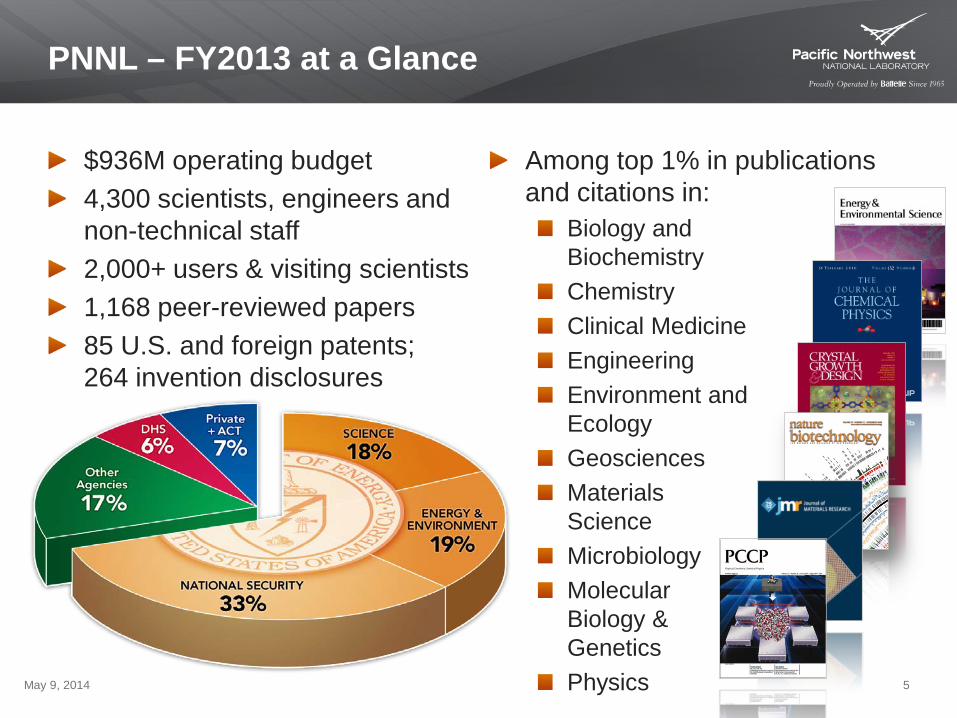
$936M operating budget 4,300 scientists, engineers and non-technical staff 2,000+ users & visiting scientists 1,168 peer-reviewed papers 85 U.S. and foreign patents; 264 invention disclosures
May 9, 2014 5
Among top 1% in publications and citations in:
Biology and Biochemistry Chemistry Clinical Medicine Engineering Environment and Ecology Geosciences Materials Science Microbiology Molecular Biology & Genetics Physics
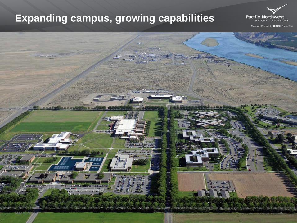
Expanding campus, growing capabilities
May 9, 2014 6
Bioproducts, Sciences and Engineering Laboratory
Discovery in processes for bio-based product manufacture
High-pressure catalytic reactor rooms Development and engineering of fungal fermentations Synthesis and preparation of catalysts and feedstocks Catalysis research laboratory Analytical chemistry
May 9, 2014 7
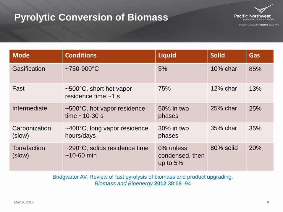
Pyrolytic Conversion of Biomass
May 9, 2014 8
Mode Conditions Liquid Solid Gas
Gasification ~750-900°C 5% 10% char 85%
Fast ~500°C, short hot vapor residence time ~1 s
75% 12% char 13%
Intermediate ~500°C, hot vapor residence time ~10-30 s
50% in two phases
25% char 25%
Carbonization (slow)
~400°C, long vapor residence hours/days
30% in two phases
35% char 35%
Torrefaction (slow)
~290°C, solids residence time ~10-60 min
0% unless condensed, then up to 5%
80% solid 20%
Bridgwater AV. Review of fast pyrolysis of biomass and product upgrading. Biomass and Bioenergy 2012 38:68–94
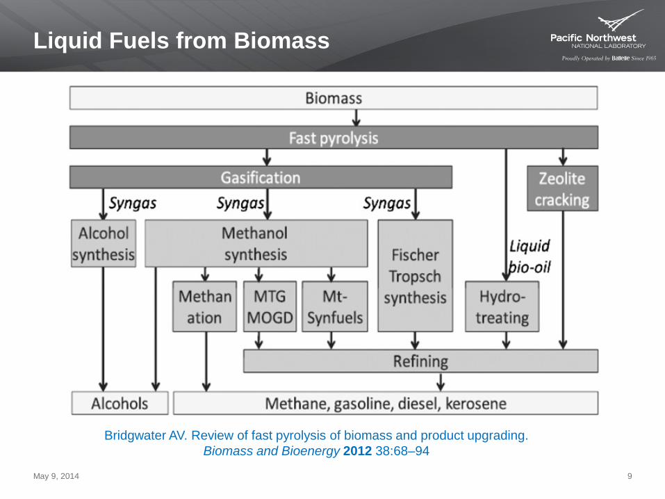
Liquid Fuels from Biomass
May 9, 2014 9
Bridgwater AV. Review of fast pyrolysis of biomass and product upgrading. Biomass and Bioenergy 2012 38:68–94
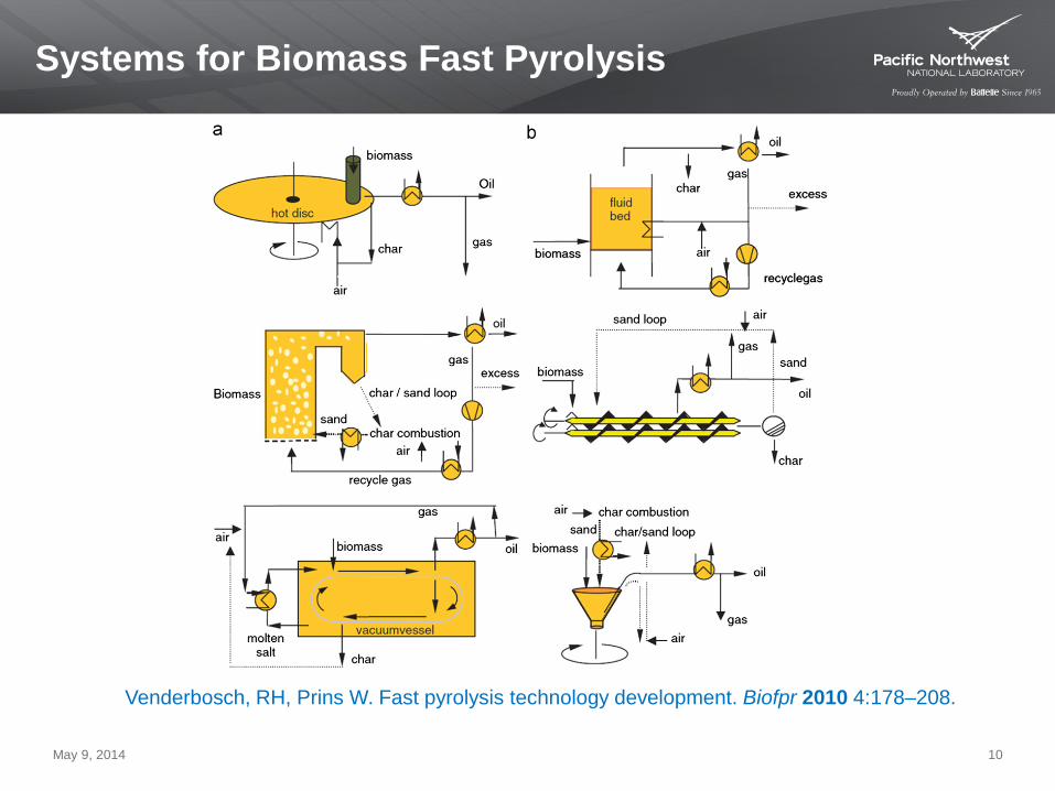
Systems for Biomass Fast Pyrolysis
May 9, 2014 10
Venderbosch, RH, Prins W. Fast pyrolysis technology development. Biofpr 2010 4:178–208.
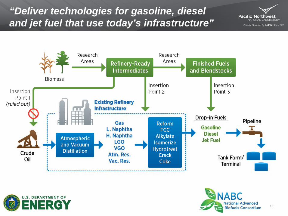
“Deliver technologies for gasoline, diesel and jet fuel that use today’s infrastructure”
11

Technical Approach and Strategy
May 9, 2014 12
Liquefaction Develop an understanding of intermediate bio-oil quality and how to improve It Conceptually—
In field remove O as CO2
Yield versus quality trade-offs Pathways
Fast Pyrolysis Catalytic Pyrolysis Hydropyrolysis Hydrothermal Liquefaction Catalytic Liquefaction Mixed oxygenates
Upgrading Reduce process intensity, improve fit for purpose (fuels of choice) Improve catalyst life and activity Conceptually—
Remove O as H2O Retain carbon yield in final product
Pathways HDO (remove O) Ketonization/condensation (improve C yield) Cracking (improve quality)
Lack of understanding of fundamental reactions and species

Pyrolysis and Upgrading
The Opportunity with Fast Pyrolysis High bio-oil yield with relatively low capital cost
Low quality with high volatile content containing acids, carbonyls and unsaturation Improved robust catalysts for upgrading thermally unstable oils HDO yield is consistent at 0.4g product/g bio-oil (due to O loss) Can we improve the quantity and quality of the jet and diesel fraction?
Fast pyrolysis bio-oil composition
Hydrotreat
Upgraded Oil
May 9, 2014 13

Hydrotreating of Pyrolysis Bio-oils
fast pyrolyzer
500°C 1-2 sec
HC
light products
medium products
heavy products
hydrogen recycle and byproduct gas reforming
char byproduct
H2
biomass
HT
aqueous byproduct
gas byproduct
aqueous byproduct
bio-oil
May 9, 2014 14

Fluidized-Bed Fast Pyrolysis System
May 9, 2014 15
FEED HOPPER
Wet Test Meter
EXHAUST
Hydrocarbon HX
PRODUCT TANK
SP
RA
Y TOW
ER
FLUID
IZED
BE
D
RE
AC
TOR
P
UM
P1
PU
MP
2
Coalescer #2
Secondary hopper
High speed screw
Metered screw
Heated Nitrogen
Cyclones
Packing tow
er
Coalescer #1
Dry ice trap
Solids Collection Liquid Collection Gas Collection
GC
Hydrocarbon quench circulation flow
• 1 kg/h • 1.6s vapor
residence time
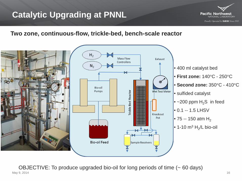
Catalytic Upgrading at PNNL
Two zone, continuous-flow, trickle-bed, bench-scale reactor
• 400 ml catalyst bed
• First zone: 140°C - 250°C
• Second zone: 350°C - 410°C
• sulfided catalyst
• ~200 ppm H2S in feed
• 0.1 -- 1.5 LHSV
• 75 -- 150 atm H2
• 1-10 m3 H2/L bio-oil
OBJECTIVE: To produce upgraded bio-oil for long periods of time (~ 60 days) May 9, 2014 16

Stabilization in the Upgrading Process
• T < 200°C
• 0.5 LHSV
• 68 atm H2
• 1-10 m3 H2/L bio-oil
• non-sulfided catalyst May 9, 2014 17
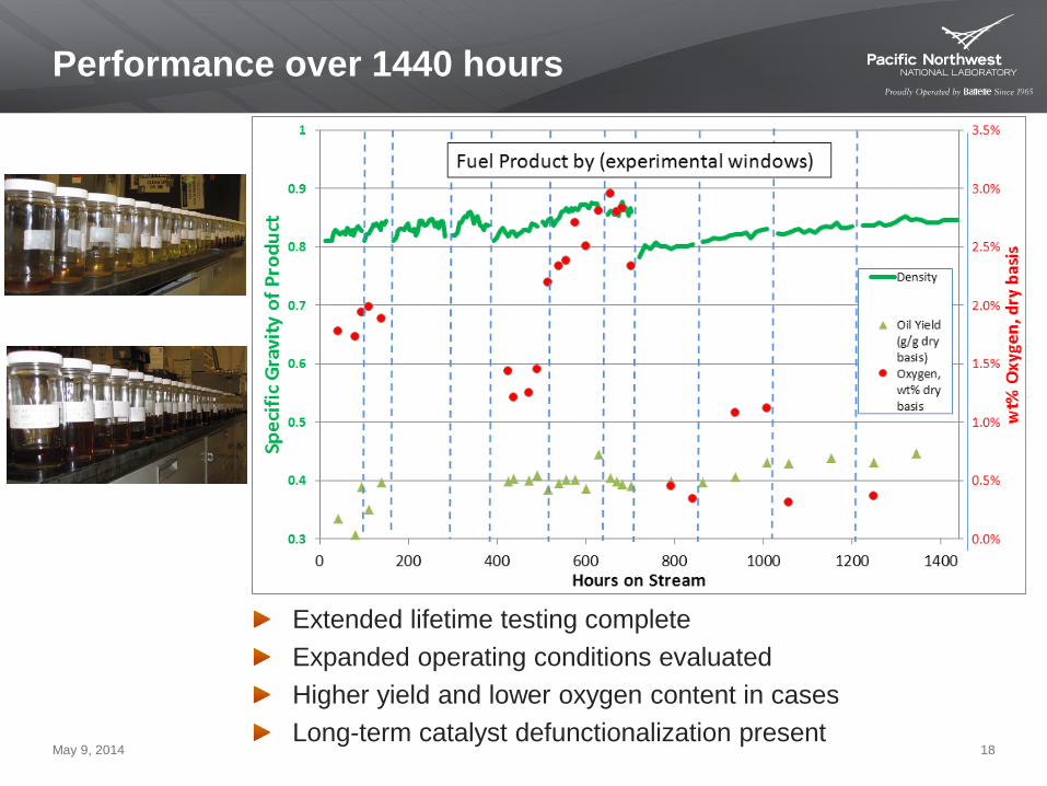
Performance over 1440 hours
Extended lifetime testing complete Expanded operating conditions evaluated Higher yield and lower oxygen content in cases Long-term catalyst defunctionalization present
May 9, 2014 18
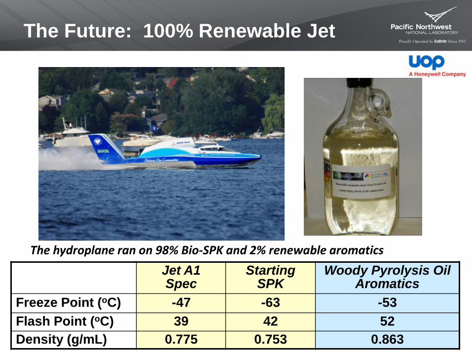
The Future: 100% Renewable Jet
May 9, 2014 19
The hydroplane ran on 98% Bio-SPK and 2% renewable aromatics Jet A1
Spec Starting
SPK Woody Pyrolysis Oil
Aromatics Freeze Point (oC) -47 -63 -53 Flash Point (oC) 39 42 52 Density (g/mL) 0.775 0.753 0.863
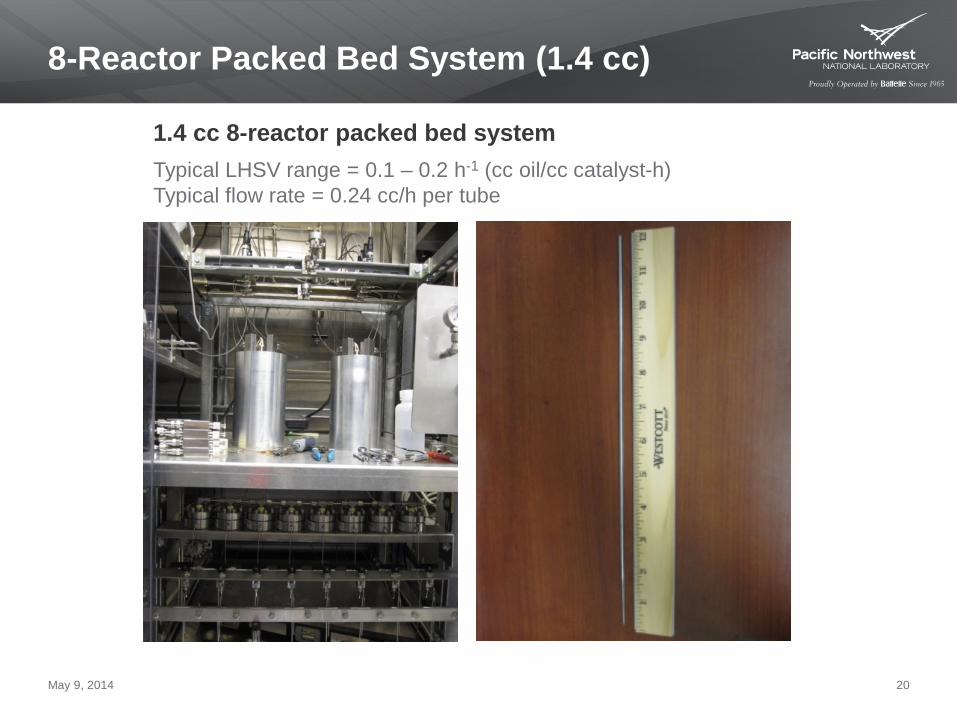
8-Reactor Packed Bed System (1.4 cc)
1.4 cc 8-reactor packed bed system Typical LHSV range = 0.1 – 0.2 h-1 (cc oil/cc catalyst-h) Typical flow rate = 0.24 cc/h per tube
May 9, 2014 20
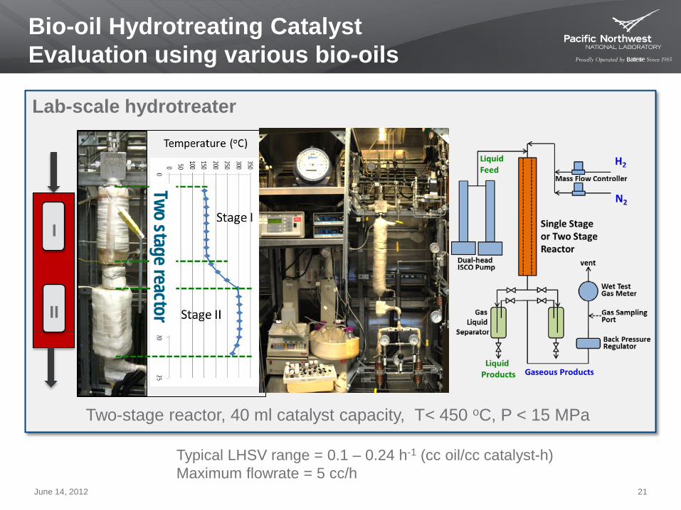
Bio-oil Hydrotreating Catalyst Evaluation using various bio-oils
Two stage reactor
Lab-scale hydrotreater
Two-stage reactor, 40 ml catalyst capacity, T< 450 oC, P < 15 MPa
I
II
June 14, 2012 21
Typical LHSV range = 0.1 – 0.24 h-1 (cc oil/cc catalyst-h) Maximum flowrate = 5 cc/h

Hydrotreating Catalyst Bed Design
Challenge: Catalyst Lifetime
Fast Pyrolysis Hydrotreatment
char Ligno-cellulosic biomass
gas
aqueous
FLUID
IZED
BE
D
RE
AC
TOR
Diesel Jet Fuel Gasoline
H2
Bio-oil
Gas
recy
cle
Ebul
late
d Be
d
Liqu
id re
cycl
e
Gas recycle/ reforming
H2
HC
HT
Bio-oil
May 9, 2014 22

Scaled-up Catalytic Hydrotreater
9-zone fixed-bed catalytic hydrotreater (20 L) Atmospheric distilling column for fuel fraction collection
May 9, 2014 23

UOP Integrated Biorefinery Demo Kapolei, Oahu, Hawaii
$25 M DOE funded with equal industrial cost share Integrated pyrolysis (RTP), bio-oil preparation (Upgrader I) and hydroprocessing (Upgrader II) 1 t/d = 4 bpd
gasoline diesel jet fuel
construction mid-2011 to 2015
operations 2012 and 2015 detailed life cycle assessment and growth potential
commercialization plan = 4 RTP units and 1 upgrading unit to produce 50 million gallons of fuels annually
May 9, 2014 24
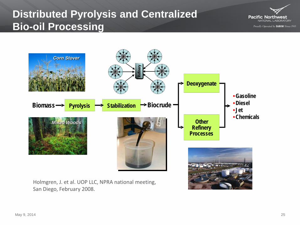
Distributed Pyrolysis and Centralized Bio-oil Processing
Holmgren, J. et al. UOP LLC, NPRA national meeting, San Diego, February 2008.
Stabilization Pyrolysis Biomass
Mixed Woods Mixed Woods
Corn Stover Corn Stover
Deoxygenate
Gasoline Diesel Jet Chemicals
Other Refinery
Processes
Biocrude
Refin
ery
P P
P P
P P
Refin
ery
P P
P P
P P
May 9, 2014 25

IEA Bioenergy is an international collaboration set up in 1978 by the International Energy Agency (IEA) as one of “Implementing Agreements” within IEA’s Energy Technology Network
www.ieabioenergy.com
May 9, 2014 26

IEA Bioenergy Tasks
The work of IEA Bioenergy is structured in a number
of Tasks, which have well defined objectives, budgets, and time frames.
Their activities include:
• Coordination of national RD&D programs,
information exchange and joint projects • Task meetings, study tours and workshops • Publications, reports, newsletters, websites • Networking with industrial and other stakeholders
May 9, 2014 27

23 Contracting Parties
• Australia • Austria • Belgium • Brazil • Canada • Croatia • Denmark • European Commission • Finland • France • Germany • Ireland
• Italy • Japan • Korea • Netherlands • New Zealand • Norway • South Africa • Sweden • Switzerland • United Kingdom • United States
May 9, 2014 28

10 Tasks in three areas
• Feedstock Forest and agricultural products, MSW and recovered fuels
• Conversion Combustion, gasification, pyrolysis, anaerobic digestion, fermentation, biorefineries
• Integrating Research Issues GHG balances, socioeconomic drivers, international trade, systems analysis
May 9, 2014 29
Task 34 Pyrolysis Approved Plan for 2013-2015
Objective: To facilitate commercialization of biomass fast pyrolysis, -- maximize liquid product yield and quality -- produce renewable fuel oil and transportation fuels
Priority Topics
Review of Bio-oil Applications Bio-oil Standardization Support Round Robin for Method Validation TEAs of Biomass Pyrolysis Application Technologies
May 9, 2014 30
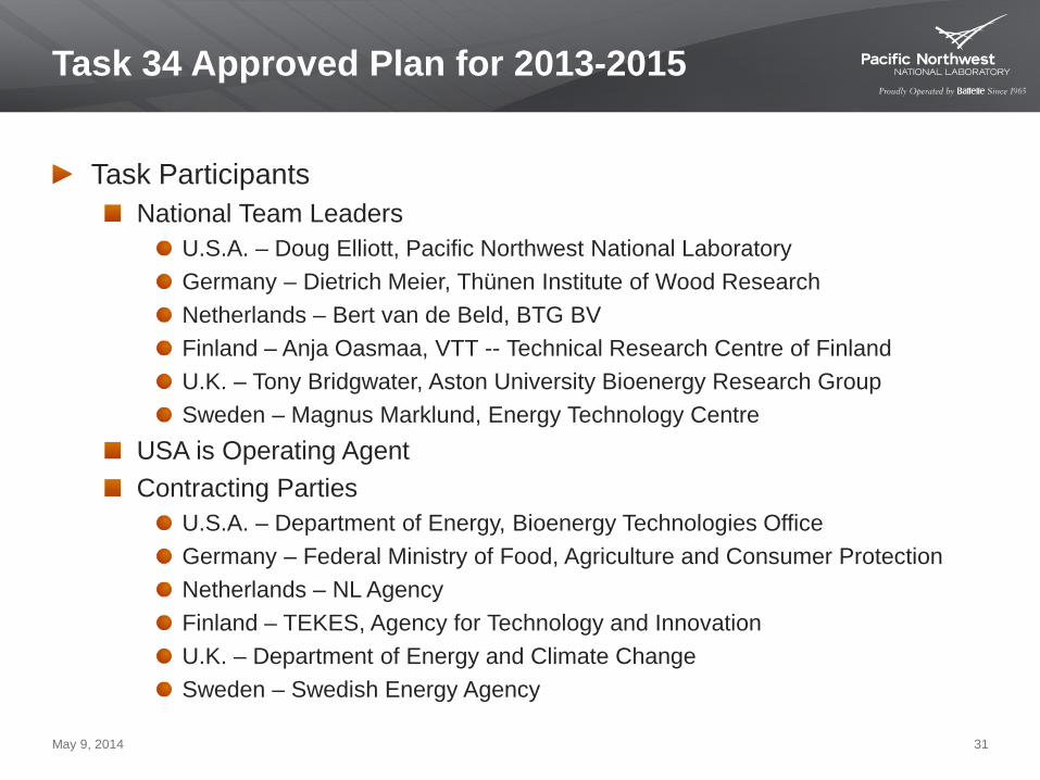
Task 34 Approved Plan for 2013-2015
Task Participants National Team Leaders
U.S.A. – Doug Elliott, Pacific Northwest National Laboratory Germany – Dietrich Meier, Thünen Institute of Wood Research Netherlands – Bert van de Beld, BTG BV Finland – Anja Oasmaa, VTT -- Technical Research Centre of Finland U.K. – Tony Bridgwater, Aston University Bioenergy Research Group Sweden – Magnus Marklund, Energy Technology Centre
USA is Operating Agent Contracting Parties
U.S.A. – Department of Energy, Bioenergy Technologies Office Germany – Federal Ministry of Food, Agriculture and Consumer Protection Netherlands – NL Agency Finland – TEKES, Agency for Technology and Innovation U.K. – Department of Energy and Climate Change Sweden – Swedish Energy Agency
May 9, 2014 31

Project Plan
Review of Bio-oil Applications Near-term emphasis Market size, resource size, property impacts Deliverable—journal article (update Oasmaa, Gust, Peacocke et al.)
Bio-oil Standardization Support implementation of standard methods
CEN ASTM REACH
Deliverable—Improved MSDS
Round Robin Bio-oil production with standardized feedstock and centralized analysis Deliverable—journal article publication of evaluation of results
May 9, 2014 32
Project Plan, cont.
Technoeconomic assessments Evaluate various biomass pyrolysis application routes Deliverable--TEA to be published by TBD
Proposed Inter-task collaborations
TEA of bio-oil combustion to compare to solid biomass combustion (Task 32) TEA of bio-oil gasification to compare to solid biomass gasification (Task 33) Use TEAs to develop LCAs (Task 38) Development of operations database (Task 39, 33, ExCo) Evaluation of a pyrolysis-based biorefinery (Task 42)
May 9, 2014 33
Continuing Task Activities
Round Robin on bio-oil production 15 participants will provide bio-oil products for centralized analysis
IEA Bioenergy web database Data input for pyrolysis plants will be generated
Collaboration on LCA of biomass liquefaction processes LCA being prepared and will be reviewed by Task 38
Planned participation with Task 42 meeting in Hamburg in June Comparison of biomass and bio-oil gasification continues
May 9, 2014 34

A commercial application …
Savon Voima Oyj, Local energy production and distribution company in North Savo region, Finland. Has built a bio-oil compatible district heating plant in Iisalmi, Finland.
Stand-by hot water for the district heating grid. Municipal and industrial buildings as well as private houses.
Fortum (with UPM & VTT) Integrated fast pyrolysis plant in Joensuu, Finland Has signed a commercial supply contract for pyrolysis oil
Fuel delivery will start in the beginning of 2014.
May 9, 2014 35

CHP Integrated Pyrolysis Process
Fortum with UPM & VTT integrated fast pyrolysis in Joensuu, Finland
May 9, 2014 36
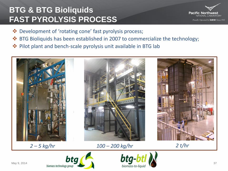
2 – 5 kg/hr 100 – 200 kg/hr 2 t/hr
Development of ‘rotating cone’ fast pyrolysis process; BTG Bioliquids has been established in 2007 to commercialize the technology; Pilot plant and bench-scale pyrolysis unit available in BTG lab
BTG & BTG Bioliquids FAST PYROLYSIS PROCESS
May 9, 2014 37
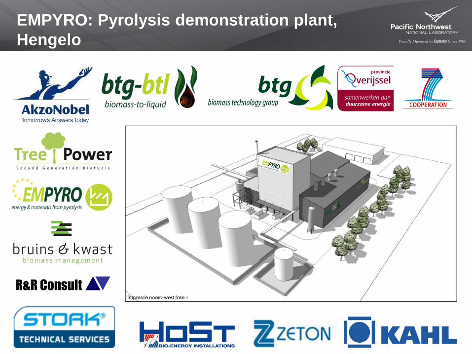
EMPYRO: Pyrolysis demonstration plant, Hengelo

Basic plant configuration: Single reactor Pyrolysis gas and flue gas afterburning at 850 °C Integrated combustor/boiler External sand cooler Single-stage, low temperature, oil spray-
condensor
Basic data of the plant: Capacity = 5 t dry biomass/hr Oil Production = 3.2 t/hr Steam production = 2.5 MW Electricity production = 700 kWe
22m
EMPYRO: Pyrolysis demonstration plant, Hengelo
May 9, 2014 39
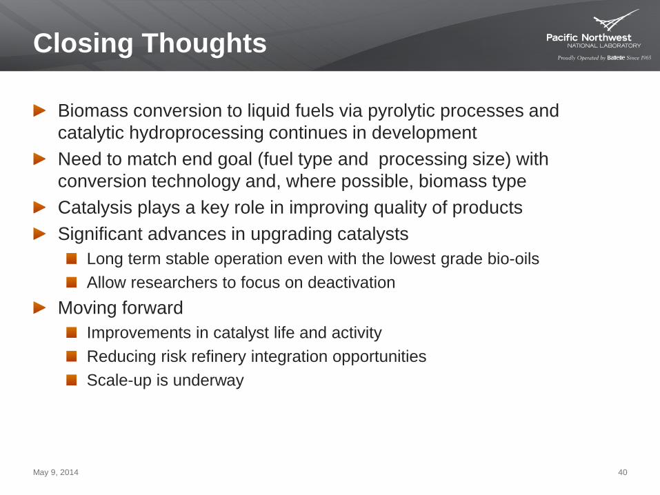
Closing Thoughts
Biomass conversion to liquid fuels via pyrolytic processes and catalytic hydroprocessing continues in development Need to match end goal (fuel type and processing size) with conversion technology and, where possible, biomass type Catalysis plays a key role in improving quality of products Significant advances in upgrading catalysts
Long term stable operation even with the lowest grade bio-oils Allow researchers to focus on deactivation
Moving forward Improvements in catalyst life and activity Reducing risk refinery integration opportunities Scale-up is underway
May 9, 2014 40
Thank You! Acknowledgement:
Hydroprocessing Gary Neuenschwander Mariefel Olarte LJ Rotness Huamin Wang
Bio-oil Production Miki Santosa LJ Rotness Todd Hart Dan Howe
Management John Holladay Corinne Drennan Rick Orth