Embed Size (px)
Citation preview
RTI International is a trade name of Research Triangle Institute. www.rti.org
Catalytic Biomass
Pyrolysis Technology
Development for
Advanced Biofuels
David C. Dayton
Director of Biofuels
Energy Technology Division
RTI International
September 5, 2013
RTI International
turning knowledge
into practice
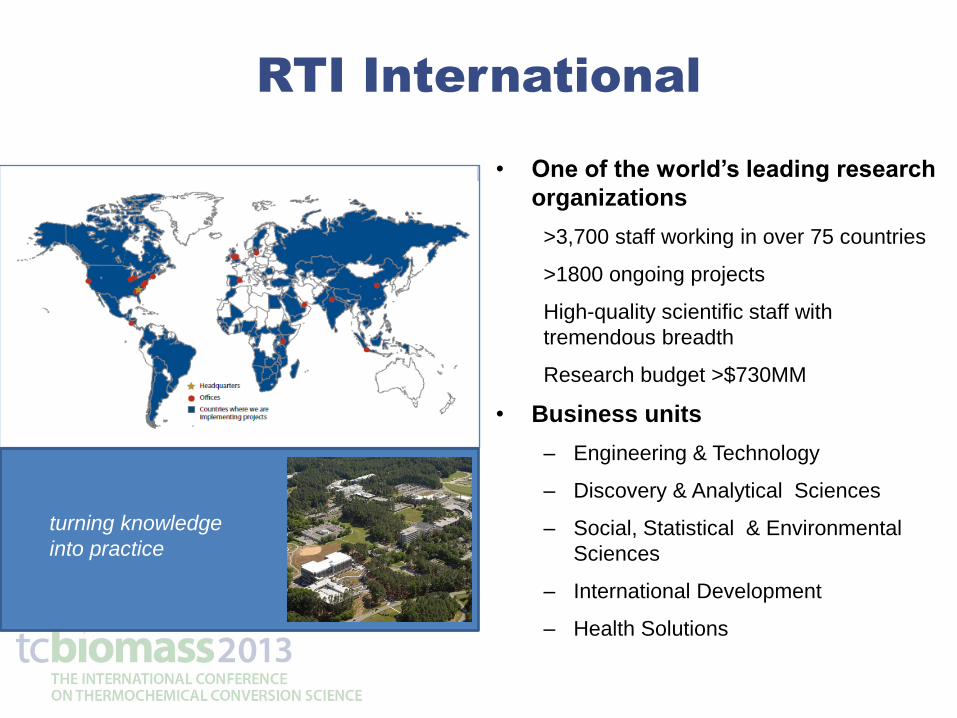
• One of the world’s leading research
organizations
>3,700 staff working in over 75 countries
>1800 ongoing projects
High-quality scientific staff with
tremendous breadth
Research budget >$730MM
• Business units
– Engineering & Technology
– Discovery & Analytical Sciences
– Social, Statistical & Environmental
Sciences
– International Development
– Health Solutions
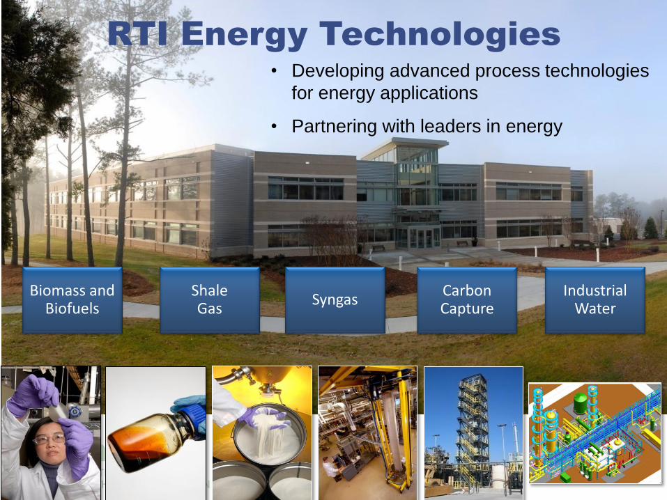
RTI Energy Technologies
Biomass and Biofuels
Shale Gas
Syngas Carbon Capture
Industrial Water
• Developing advanced process technologies
for energy applications
• Partnering with leaders in energy
Advanced Biofuels Technology
Development Approach
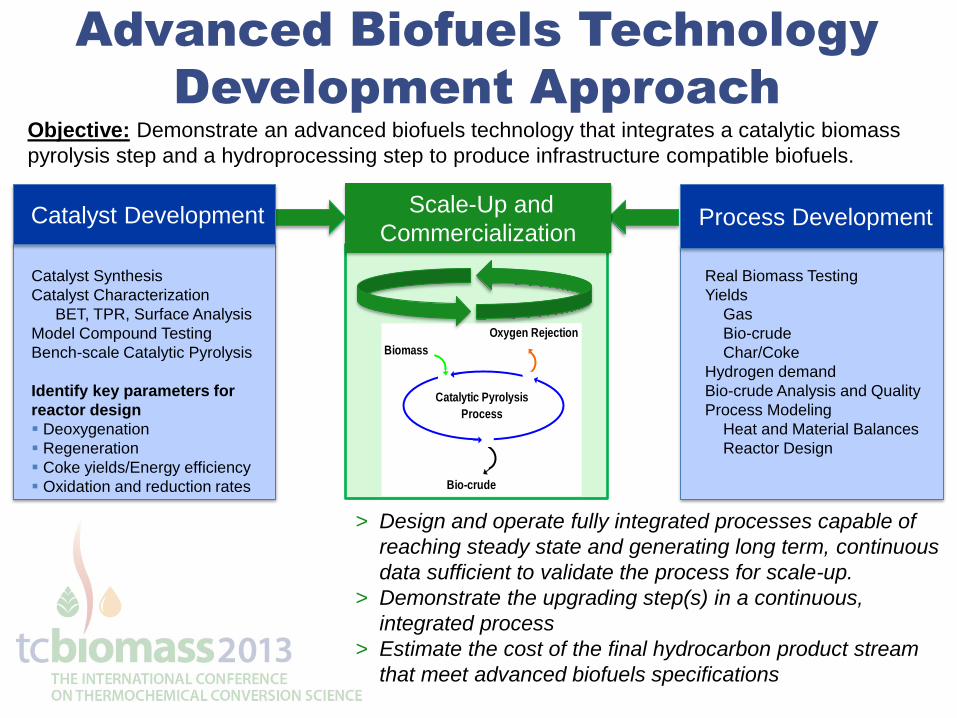
Objective: Demonstrate an advanced biofuels technology that integrates a catalytic biomass
pyrolysis step and a hydroprocessing step to produce infrastructure compatible biofuels.
> Design and operate fully integrated processes capable of
reaching steady state and generating long term, continuous
data sufficient to validate the process for scale-up.
> Demonstrate the upgrading step(s) in a continuous,
integrated process
> Estimate the cost of the final hydrocarbon product stream
that meet advanced biofuels specifications
Scale-Up and
Commercialization Process Development
Catalytic Pyrolysis
Process
Biomass
Bio-crude
Oxygen Rejection
Catalyst Synthesis
Catalyst Characterization
BET, TPR, Surface Analysis
Model Compound Testing
Bench-scale Catalytic Pyrolysis
Identify key parameters for
reactor design
Deoxygenation
Regeneration
Coke yields/Energy efficiency
Oxidation and reduction rates
Real Biomass Testing
Yields
Gas
Bio-crude
Char/Coke
Hydrogen demand
Bio-crude Analysis and Quality
Process Modeling
Heat and Material Balances
Reactor Design
Catalyst Development
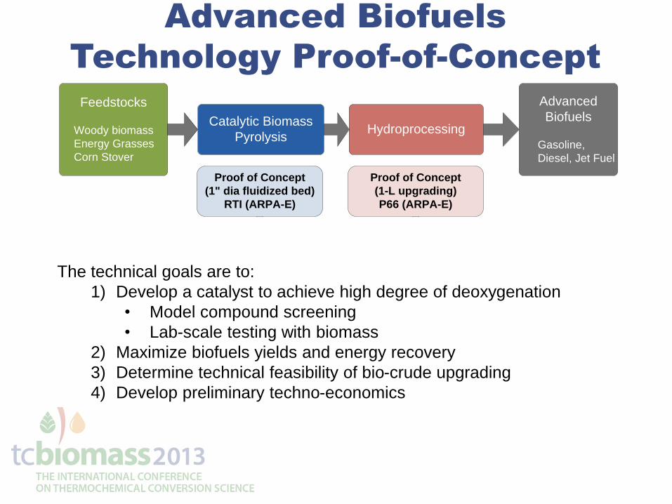
Advanced Biofuels
Technology Proof-of-Concept
Catalytic Biomass
PyrolysisHydroprocessing
Feedstocks
Woody biomass
Energy Grasses
Corn Stover
Advanced
Biofuels
Gasoline,
Diesel, Jet Fuel
Proof of Concept
(1" dia fluidized bed)
RTI (ARPA-E)
Bench-scale
(1 TPD)
RTI (BETO)
Proof of Concept
(1-L upgrading)
P66 (ARPA-E)
Bench-scale
(250-mL integrated)
Haldor Topsøe (BETO)
The technical goals are to:
1) Develop a catalyst to achieve high degree of deoxygenation
• Model compound screening
• Lab-scale testing with biomass
2) Maximize biofuels yields and energy recovery
3) Determine technical feasibility of bio-crude upgrading
4) Develop preliminary techno-economics
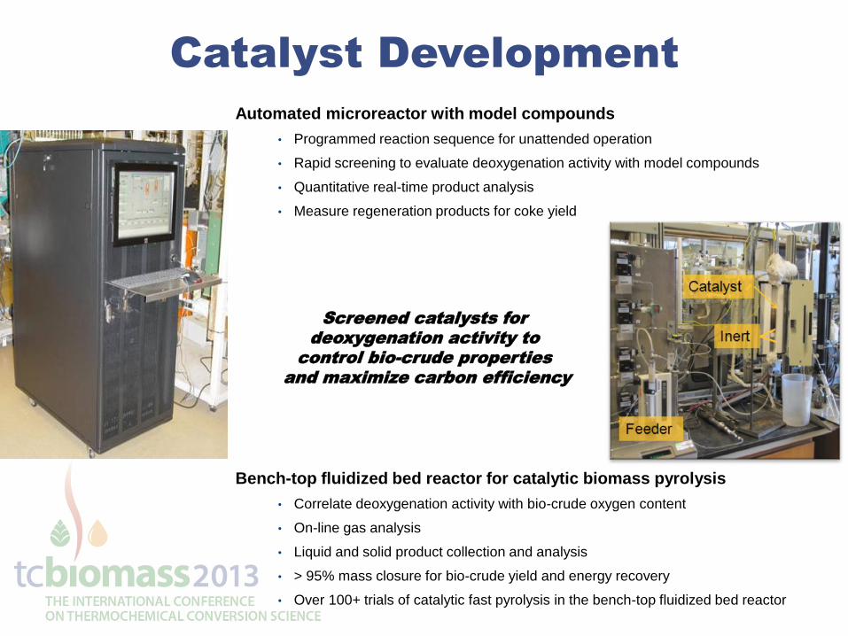
Catalyst Development
Screened catalysts for
deoxygenation activity to
control bio-crude properties
and maximize carbon efficiency
Automated microreactor with model compounds
• Programmed reaction sequence for unattended operation
• Rapid screening to evaluate deoxygenation activity with model compounds
• Quantitative real-time product analysis
• Measure regeneration products for coke yield
Bench-top fluidized bed reactor for catalytic biomass pyrolysis
• Correlate deoxygenation activity with bio-crude oxygen content
• On-line gas analysis
• Liquid and solid product collection and analysis
• > 95% mass closure for bio-crude yield and energy recovery
• Over 100+ trials of catalytic fast pyrolysis in the bench-top fluidized bed reactor
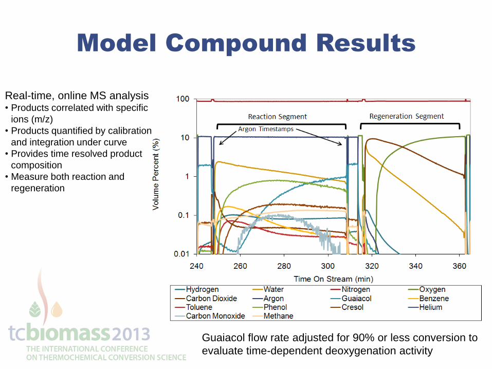
Model Compound Results
Real-time, online MS analysis
• Products correlated with specific
ions (m/z)
• Products quantified by calibration
and integration under curve
• Provides time resolved product
composition
• Measure both reaction and
regeneration
Guaiacol flow rate adjusted for 90% or less conversion to
evaluate time-dependent deoxygenation activity
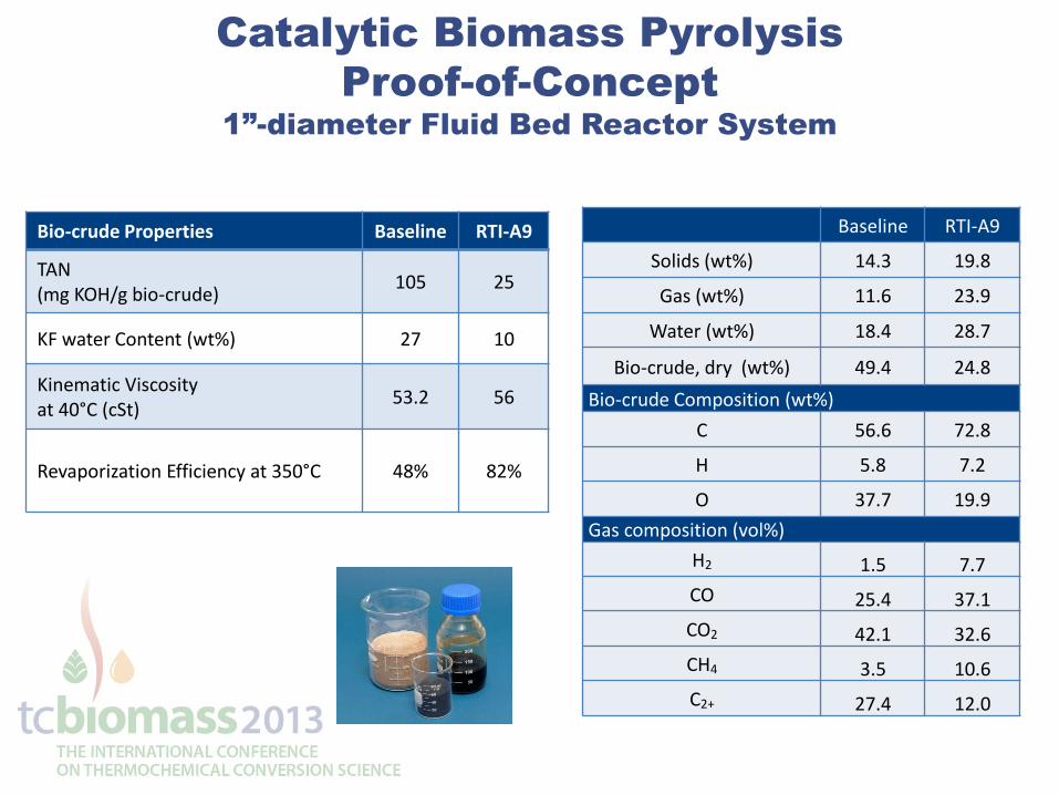
Catalytic Biomass Pyrolysis
Proof-of-Concept
1”-diameter Fluid Bed Reactor System
Bio-crude Properties Baseline RTI-A9
TAN (mg KOH/g bio-crude)
105 25
KF water Content (wt%) 27 10
Kinematic Viscosity at 40°C (cSt)
53.2 56
Revaporization Efficiency at 350°C 48% 82%
Baseline RTI-A9
Solids (wt%) 14.3 19.8
Gas (wt%) 11.6 23.9
Water (wt%) 18.4 28.7
Bio-crude, dry (wt%) 49.4 24.8
Bio-crude Composition (wt%)
C 56.6 72.8
H 5.8 7.2
O 37.7 19.9
Gas composition (vol%)
H2 1.5 7.7
CO 25.4 37.1
CO2 42.1 32.6
CH4 3.5 10.6
C2+ 27.4 12.0
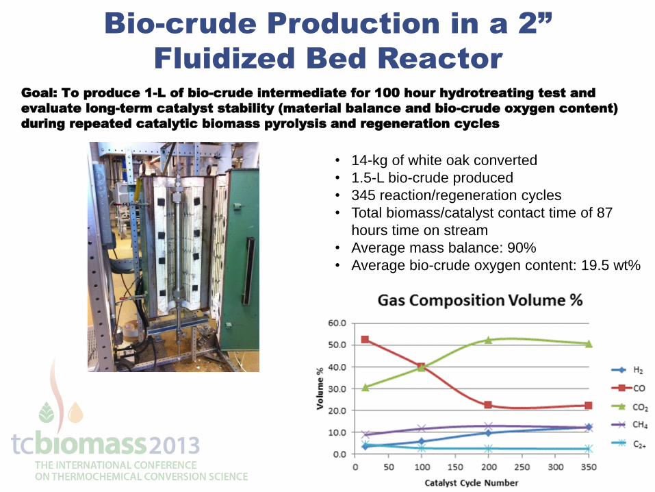
Bio-crude Production in a 2”
Fluidized Bed Reactor
• 14-kg of white oak converted
• 1.5-L bio-crude produced
• 345 reaction/regeneration cycles
• Total biomass/catalyst contact time of 87
hours time on stream
• Average mass balance: 90%
• Average bio-crude oxygen content: 19.5 wt%
Goal: To produce 1-L of bio-crude intermediate for 100 hour hydrotreating test and
evaluate long-term catalyst stability (material balance and bio-crude oxygen content)
during repeated catalytic biomass pyrolysis and regeneration cycles
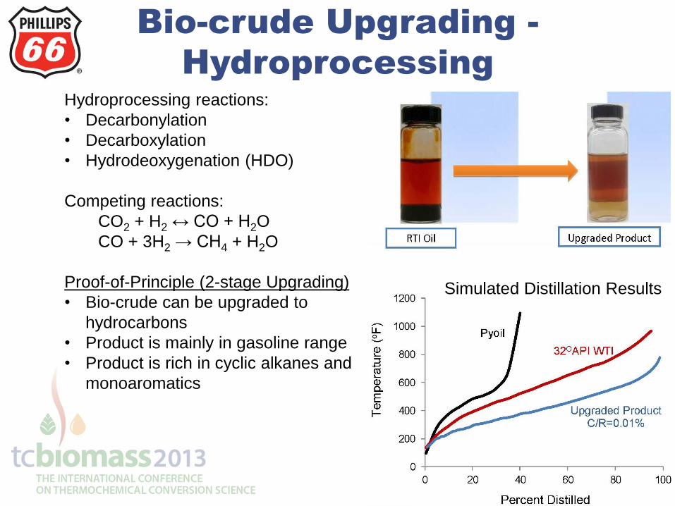
Bio-crude Upgrading -
Hydroprocessing
Hydroprocessing reactions:
• Decarbonylation
• Decarboxylation
• Hydrodeoxygenation (HDO)
Competing reactions:
CO2 + H2 ↔ CO + H2O
CO + 3H2 → CH4 + H2O
Proof-of-Principle (2-stage Upgrading)
• Bio-crude can be upgraded to
hydrocarbons
• Product is mainly in gasoline range
• Product is rich in cyclic alkanes and
monoaromatics
Simulated Distillation Results
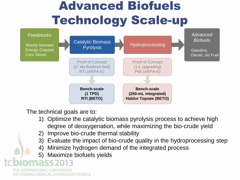
Advanced Biofuels
Technology Scale-up
The technical goals are to:
1) Optimize the catalytic biomass pyrolysis process to achieve high
degree of deoxygenation, while maximizing the bio-crude yield
2) Improve bio-crude thermal stability
3) Evaluate the impact of bio-crude quality in the hydroprocessing step
4) Minimize hydrogen demand of the integrated process
5) Maximize biofuels yields
Catalytic Biomass
PyrolysisHydroprocessing
Feedstocks
Woody biomass
Energy Grasses
Corn Stover
Advanced
Biofuels
Gasoline,
Diesel, Jet Fuel
Proof of Concept
(1" dia fluidized bed)
RTI (ARPA-E)
Bench-scale
(1 TPD)
RTI (BETO)
Proof of Concept
(1-L upgrading)
P66 (ARPA-E)
Bench-scale
(250-mL integrated)
Haldor Topsøe (BETO)
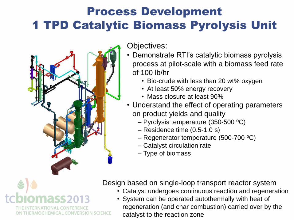
Process Development
1 TPD Catalytic Biomass Pyrolysis Unit
Objectives: • Demonstrate RTI’s catalytic biomass pyrolysis
process at pilot-scale with a biomass feed rate
of 100 lb/hr • Bio-crude with less than 20 wt% oxygen
• At least 50% energy recovery
• Mass closure at least 90%
• Understand the effect of operating parameters
on product yields and quality – Pyrolysis temperature (350-500 ºC)
– Residence time (0.5-1.0 s)
– Regenerator temperature (500-700 ºC)
– Catalyst circulation rate
– Type of biomass
Design based on single-loop transport reactor system • Catalyst undergoes continuous reaction and regeneration
• System can be operated autothermally with heat of
regeneration (and char combustion) carried over by the
catalyst to the reaction zone
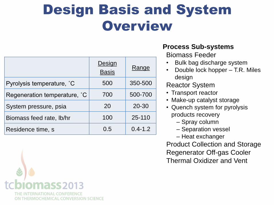
Design Basis and System
Overview
Process Sub-systems
Biomass Feeder • Bulk bag discharge system
• Double lock hopper – T.R. Miles
design
Reactor System • Transport reactor
• Make-up catalyst storage
• Quench system for pyrolysis
products recovery
– Spray column
– Separation vessel
– Heat exchanger
Product Collection and Storage
Regenerator Off-gas Cooler
Thermal Oxidizer and Vent
Design
Basis Range
Pyrolysis temperature, ˚C 500 350-500
Regeneration temperature, ˚C 700 500-700
System pressure, psia 20 20-30
Biomass feed rate, lb/hr 100 25-110
Residence time, s 0.5 0.4-1.2
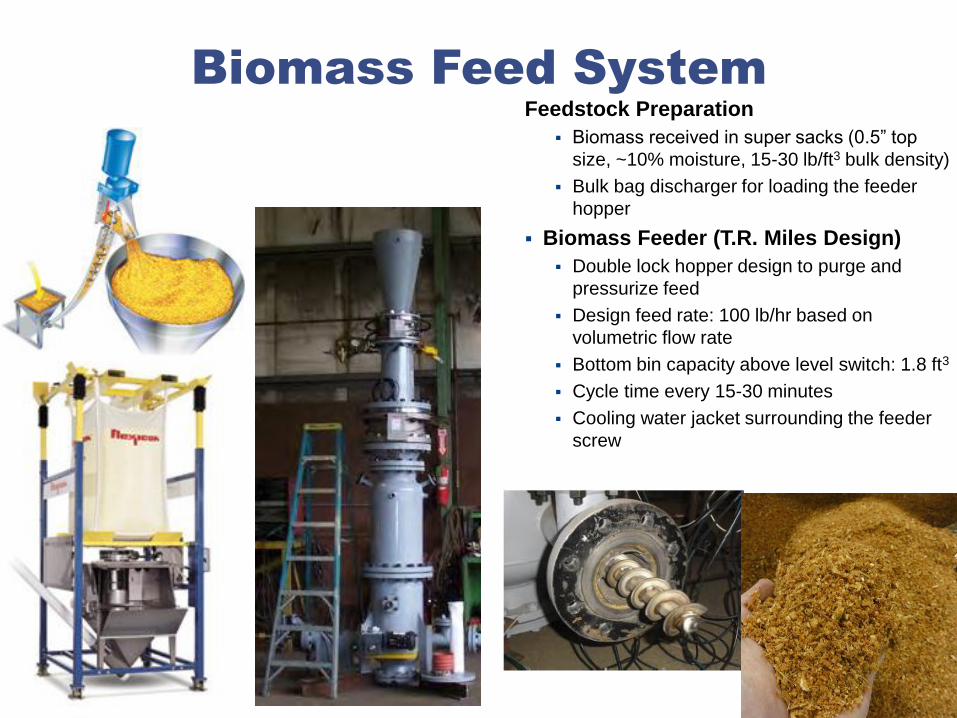
Biomass Feed System
Feedstock Preparation
Biomass received in super sacks (0.5” top
size, ~10% moisture, 15-30 lb/ft3 bulk density)
Bulk bag discharger for loading the feeder
hopper
Biomass Feeder (T.R. Miles Design)
Double lock hopper design to purge and
pressurize feed
Design feed rate: 100 lb/hr based on
volumetric flow rate
Bottom bin capacity above level switch: 1.8 ft3
Cycle time every 15-30 minutes
Cooling water jacket surrounding the feeder
screw
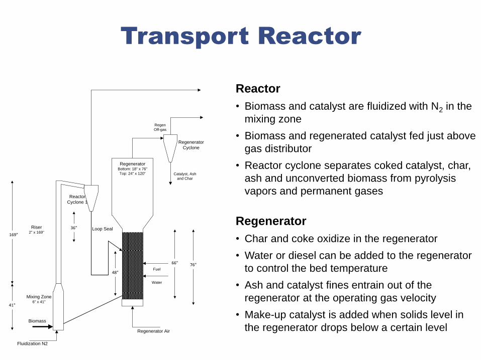
Transport Reactor
Reactor
• Biomass and catalyst are fluidized with N2 in the
mixing zone
• Biomass and regenerated catalyst fed just above
gas distributor
• Reactor cyclone separates coked catalyst, char,
ash and unconverted biomass from pyrolysis
vapors and permanent gases
Regenerator
• Char and coke oxidize in the regenerator
• Water or diesel can be added to the regenerator
to control the bed temperature
• Ash and catalyst fines entrain out of the
regenerator at the operating gas velocity
• Make-up catalyst is added when solids level in
the regenerator drops below a certain level
Regenerator
Cyclone
Reactor
Cyclone 1
Regen
Off-gas
Catalyst, Ash
and Char
Riser2" x 169"
Mixing Zone6" x 41"
Loop Seal
Regenerator Air
169"
41"
36"
RegeneratorBottom: 18" x 76"
Top: 24" x 120"
Biomass
48"
76"
Fluidization N2
66"
Fuel
Water
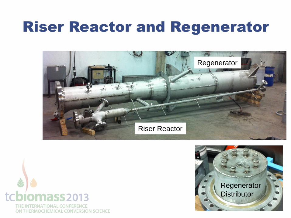
Riser Reactor and Regenerator
Riser Reactor
Regenerator
Regenerator
Distributor
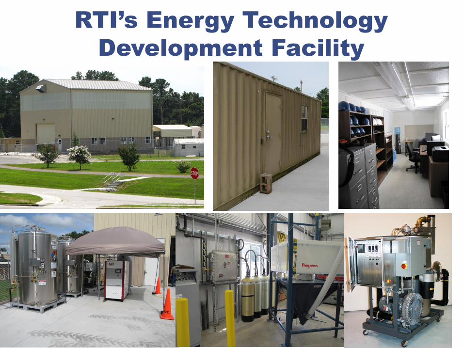
RTI’s Energy Technology
Development Facility
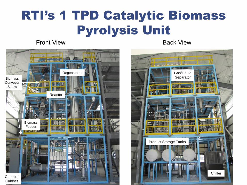
RTI’s 1 TPD Catalytic Biomass
Pyrolysis Unit
Front View Back View
Biomass
Conveyer
Screw
Biomass
Feeder
Regenerator
Reactor
Product Storage Tanks
Gas/Liquid
Separator
Chiller Controls
Cabinet
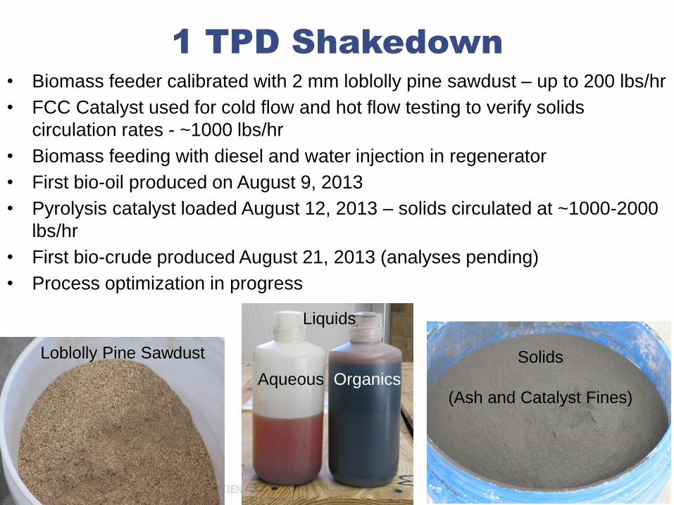
1 TPD Shakedown
• Biomass feeder calibrated with 2 mm loblolly pine sawdust – up to 200 lbs/hr
• FCC Catalyst used for cold flow and hot flow testing to verify solids
circulation rates - ~1000 lbs/hr
• Biomass feeding with diesel and water injection in regenerator
• First bio-oil produced on August 9, 2013
• Pyrolysis catalyst loaded August 12, 2013 – solids circulated at ~1000-2000
lbs/hr
• First bio-crude produced August 21, 2013 (analyses pending)
• Process optimization in progress
Loblolly Pine Sawdust
Liquids
Aqueous Organics
Solids
(Ash and Catalyst Fines)
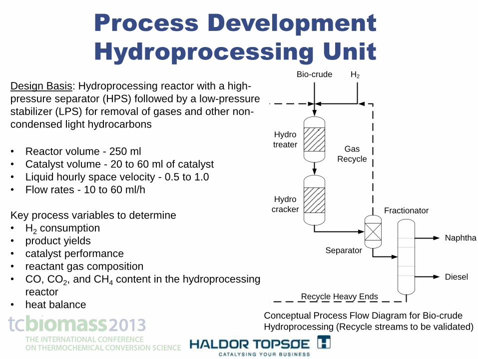
Process Development
Hydroprocessing Unit
Hydro
treater
Hydro
cracker Fractionator
Separator
Diesel
Naphtha
Gas
Recycle
Recycle Heavy Ends
H2Bio-crude
Design Basis: Hydroprocessing reactor with a high-
pressure separator (HPS) followed by a low-pressure
stabilizer (LPS) for removal of gases and other non-
condensed light hydrocarbons
• Reactor volume - 250 ml
• Catalyst volume - 20 to 60 ml of catalyst
• Liquid hourly space velocity - 0.5 to 1.0
• Flow rates - 10 to 60 ml/h
Key process variables to determine
• H2 consumption
• product yields
• catalyst performance
• reactant gas composition
• CO, CO2, and CH4 content in the hydroprocessing
reactor
• heat balance Conceptual Process Flow Diagram for Bio-crude
Hydroprocessing (Recycle streams to be validated)
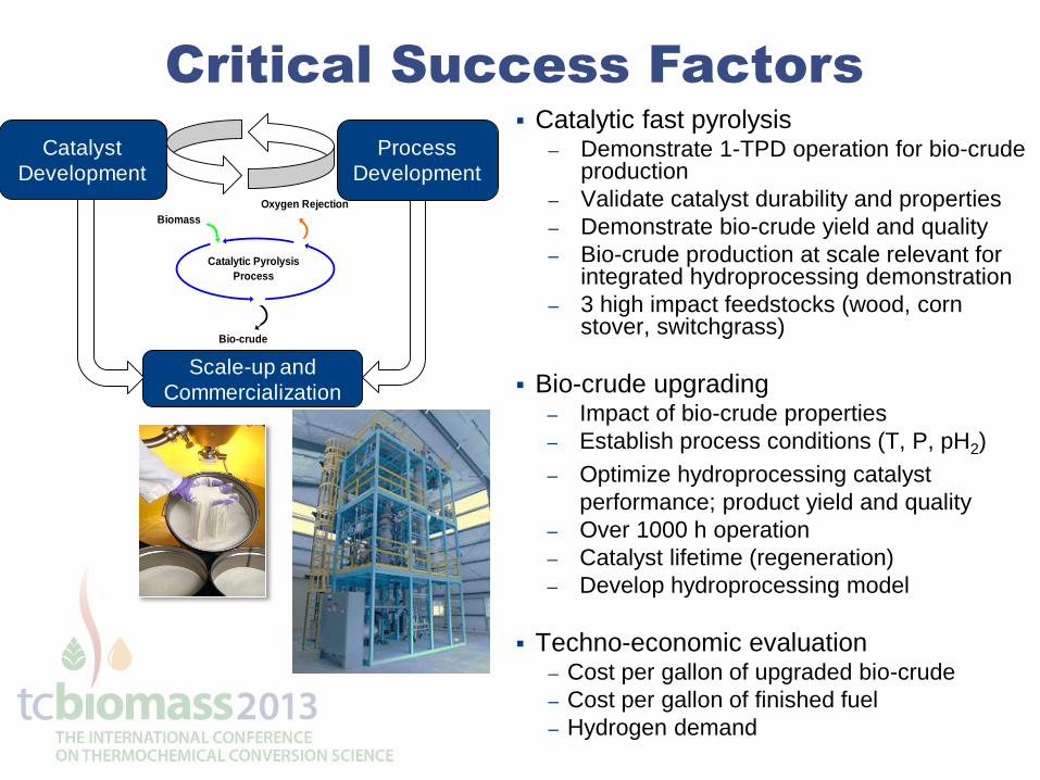
Critical Success Factors
Catalytic fast pyrolysis – Demonstrate 1-TPD operation for bio-crude
production
– Validate catalyst durability and properties
– Demonstrate bio-crude yield and quality
– Bio-crude production at scale relevant for integrated hydroprocessing demonstration
– 3 high impact feedstocks (wood, corn stover, switchgrass)
Bio-crude upgrading – Impact of bio-crude properties
– Establish process conditions (T, P, pH2)
– Optimize hydroprocessing catalyst
performance; product yield and quality
– Over 1000 h operation
– Catalyst lifetime (regeneration)
– Develop hydroprocessing model
Techno-economic evaluation – Cost per gallon of upgraded bio-crude
– Cost per gallon of finished fuel
– Hydrogen demand
Catalytic Pyrolysis
Process
Biomass
Bio-crude
Oxygen Rejection
Catalyst
Development
Process
Development
Scale-up and
Commercialization
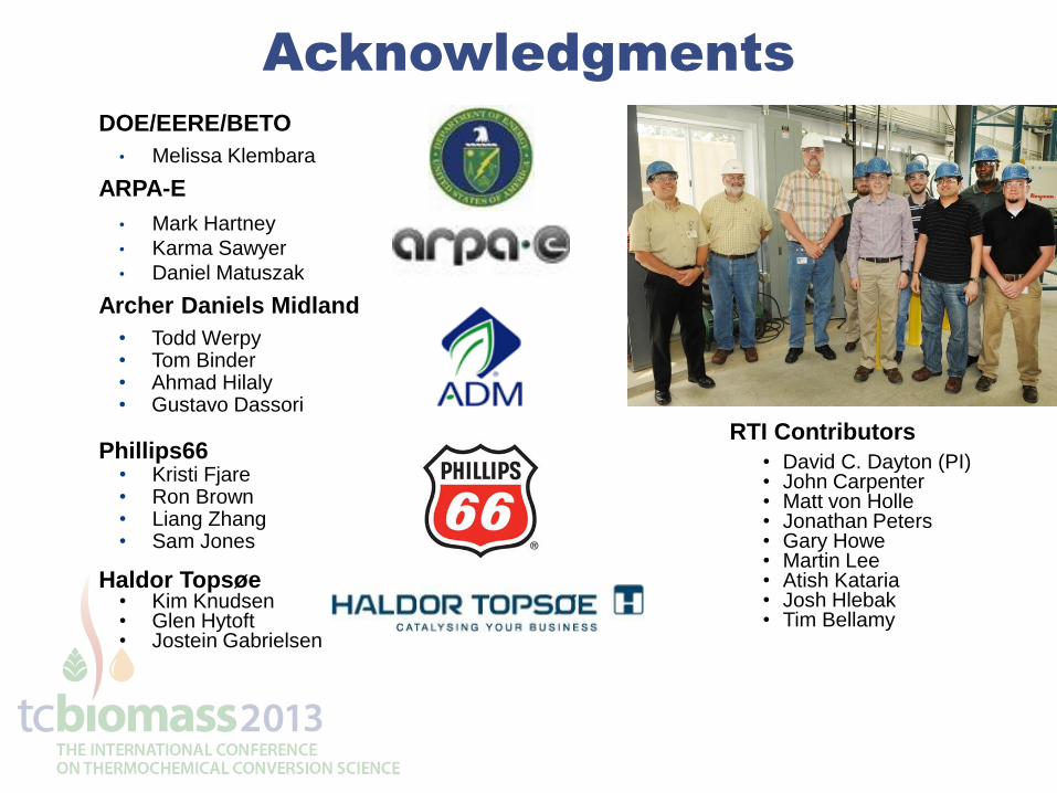
Acknowledgments
DOE/EERE/BETO
• Melissa Klembara
ARPA-E
• Mark Hartney
• Karma Sawyer
• Daniel Matuszak
Archer Daniels Midland
• Todd Werpy • Tom Binder • Ahmad Hilaly • Gustavo Dassori
Phillips66 • Kristi Fjare • Ron Brown • Liang Zhang • Sam Jones
Haldor Topsøe • Kim Knudsen • Glen Hytoft • Jostein Gabrielsen
RTI Contributors
• David C. Dayton (PI) • John Carpenter • Matt von Holle • Jonathan Peters • Gary Howe • Martin Lee • Atish Kataria • Josh Hlebak • Tim Bellamy
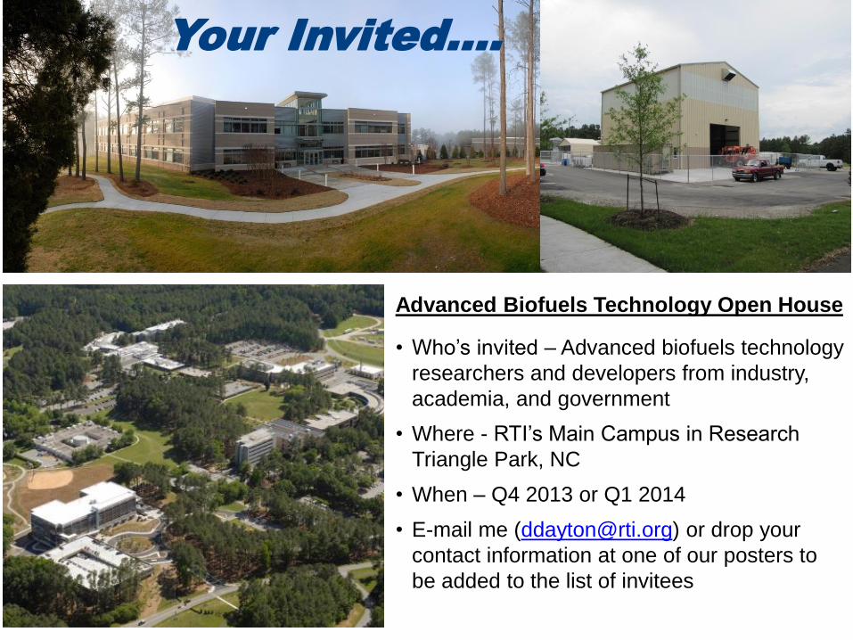
Your Invited….
Advanced Biofuels Technology Open House
• Who’s invited – Advanced biofuels technology
researchers and developers from industry,
academia, and government
• Where - RTI’s Main Campus in Research
Triangle Park, NC
• When – Q4 2013 or Q1 2014
• E-mail me ([email protected]) or drop your
contact information at one of our posters to
be added to the list of invitees
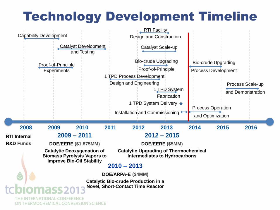
Technology Development Timeline
RTI Internal
R&D Funds
2009 – 2011
DOE/EERE ($1.875MM)
Catalytic Deoxygenation of Biomass Pyrolysis Vapors to
Improve Bio-Oil Stability 2010 – 2013
DOE/ARPA-E ($4MM)
Catalytic Bio-crude Production in a Novel, Short-Contact Time Reactor
2012 – 2015
DOE/EERE ($5MM)
Catalytic Upgrading of Thermochemical Intermediates to Hydrocarbons
2008 2009 2010 2011 2012 2013 2014 2015 2016
Proof-of-Principle
Experiments
Capability Development
Catalyst Development
and Testing
1 TPD Process Development
Design and Engineering
Catalyst Scale-up
RTI Facility
Design and Construction
1 TPD System Delivery
1 TPD System
Fabrication
Installation and Commissioning
Bio-crude Upgrading
Proof-of-Principle
Process Operation
and Optimization
Bio-crude Upgrading
Process Development
Process Scale-up
and Demonstration
![A Critical View on Catalytic Pyrolysis of Biomass · A Critical View on Catalytic Pyrolysis of Biomass R. H. Venderbosch*[a] 1. Introduction Fast pyrolysis is the rapid heating of](https://img.pdfslide.us/doc/110x75/5f5ff0368cb5bb1581292b4d/a-critical-view-on-catalytic-pyrolysis-of-biomass-a-critical-view-on-catalytic-pyrolysis.jpg)