Embed Size (px)
Citation preview
AI
RB
US
TE
CH
NI
CA
LM
AG
AZ
IN
EF
AS
T4
4
44J U L Y 2 0 0 9
F L I G H T
A I R W O R T H I N E S S
S U P P O R T
T E C H N O L O G Y FAST
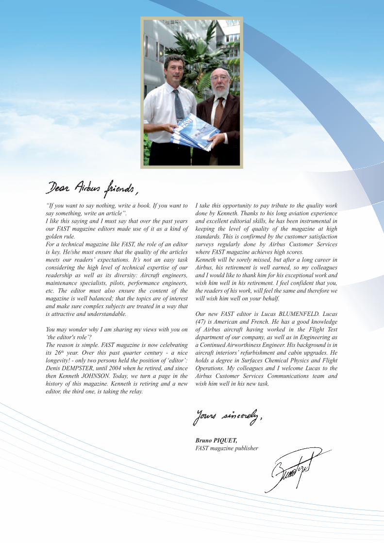
“If you want to say nothing, write a book. If you want tosay something, write an article”.I like this saying and I must say that over the past yearsour FAST magazine editors made use of it as a kind ofgolden rule.For a technical magazine like FAST, the role of an editoris key. He/she must ensure that the quality of the articlesmeets our readers’ expectations. It’s not an easy taskconsidering the high level of technical expertise of ourreadership as well as its diversity: Aircraft engineers,maintenance specialists, pilots, performance engineers,etc. The editor must also ensure the content of themagazine is well balanced; that the topics are of interestand make sure complex subjects are treated in a way thatis attractive and understandable.
You may wonder why I am sharing my views with you on‘the editor's role’?The reason is simple. FAST magazine is now celebratingits 26th year. Over this past quarter century - a nicelongevity! - only two persons held the position of ‘editor’:Denis DEMPSTER, until 2004 when he retired, and sincethen Kenneth JOHNSON. Today, we turn a page in thehistory of this magazine. Kenneth is retiring and a neweditor, the third one, is taking the relay.
I take this opportunity to pay tribute to the quality workdone by Kenneth. Thanks to his long aviation experienceand excellent editorial skills, he has been instrumental inkeeping the level of quality of the magazine at highstandards. This is confirmed by the customer satisfactionsurveys regularly done by Airbus Customer Serviceswhere FAST magazine achieves high scores.Kenneth will be sorely missed, but after a long career inAirbus, his retirement is well earned, so my colleaguesand I would like to thank him for his exceptional work andwish him well in his retirement. I feel confident that you,the readers of his work, will feel the same and therefore wewill wish him well on your behalf.
Our new FAST editor is Lucas BLUMENFELD. Lucas(47) is American and French. He has a good knowledgeof Airbus aircraft having worked in the Flight Testdepartment of our company, as well as in Engineering asa Continued Airworthiness Engineer. His background is inaircraft interiors’ refurbishment and cabin upgrades. Heholds a degree in Surfaces Chemical Physics and FlightOperations. My colleagues and I welcome Lucas to theAirbus Customer Services Communications team andwish him well in his new task.
Bruno PIQUET,FAST magazine publisher
Publisher: Bruno PIQUET
Editor: Lucas BLUMENFELD
Page layout: Quat’coul
Cover:A380 main landing gear, see article on page 17
Authorization for reprint of FAST Magazine articles should be requestedfrom the editor at the FAST Magazine e-mail address given below
Customer Services CommunicationsTel: +33 (0)5 61 93 43 88
Fax: +33 (0)5 61 93 47 73e-mail: [email protected]
Printer: Amadio
FAST Magazine may be read on Internethttp://www.content.airbusworld.com/SITES/Customer_services/index.html
under ‘Quick references’
ISSN 1293-5476
© AIRBUS S.A.S. 2009. AN EADS COMPANYAll rights reserved. Proprietary document
By taking delivery of this Magazine (hereafter “Magazine”), you accept on behalf ofyour company to comply with the following. No other property rights are granted by thedelivery of this Magazine than the right to read it, for the sole purpose of information.This Magazine, its content, illustrations and photos shall not be modified norreproduced without prior written consent of Airbus S.A.S. This Magazine and thematerials it contains shall not, in whole or in part, be sold, rented, or licensed to anythird party subject to payment or not. This Magazine may contain market-sensitive orother information that is correct at the time of going to press. This information involvesa number of factors which could change over time, affecting the true publicrepresentation. Airbus assumes no obligation to update any information contained inthis document or with respect to the information described herein. The statementsmade herein do not constitute an offer or form part of any contract. They are based onAirbus information and are expressed in good faith but no warranty or representationis given as to their accuracy. When additional information is required, Airbus S.A.S canbe contacted to provide further details. Airbus S.A.S shall assume no liability for anydamage in connection with the use of this Magazine and the materials it contains, evenif Airbus S.A.S has been advised of the likelihood of such damages. This licence isgoverned by French law and exclusive jurisdiction is given to the courts and tribunals ofToulouse (France) without prejudice to the right of Airbus to bring proceedings forinfringement of copyright or any other intellectual property right in any other court ofcompetent jurisdiction.
Airbus, its logo, A300, A310, A318, A319, A320, A321, A330,A340, A350, A380 and A400M are registered trademarks.
F L I G H T
A I R W O R T H I N E S S
S U P P O R T
T E C H N O L O G Y
J U L Y 2 0 0 7
40J U L Y 2 0 0 9
44
A320 FamilyMaintenance planning escalation packagePierre-Jean GARROT
Fuel Tank Inerting Systemalso called Flammability Reduction System (FRS)A retrofit industrial challenge for the next decadeAlain LEROUXSammy BOUGACILaurent SEGUY
Brake-to-Vacate systemThe smart automatic braking system for enhancedsurface operationsFabrice VILLAUMÉ
Implementing RNP ARThe operational approval processMatthias MAEDERErwan CADOT
Junkers G.38First air brake system
Customer ServicesEvents
Customer Services WorldwideAround the clock... Around the world
AI
RB
US
TE
CH
NI
CA
LM
AG
AZ
IN
E
FAST
44
1
2
8
17
26
31
32
33
This issue of FAST Magazine has been printedon paper produced without using chlorine, to reducewaste and help conserve natural resources.Every little helps!
Photo copyright AirbusPhoto credits:
Airbus Photographic Library, exm company, Airbus France
A320 FAMILY - MAINTENANCE PLANNING ESCALATION PACKAGEFA
ST44
2
Pierre-Jean GARROTDesign Manager
Upgrade ServicesAirbus Customer Services
A320 FamilyMaintenance planning
escalation packageStructure improvements are provided by AirbusUpgrade Services to enable structures’ main-tenance tasks escalation from five to six years.This article presents the Service Bulletin (SB)package necessary to achieve such Maintenance
Planning Document (MPD) escalation. Thisescalation is a concrete benefit for airlinesthat can reduce their direct maintenance costsrelated to corrosion inspections by an esti-mated 20%.
A320 FAMILY - MAINTENANCE PLANNING ESCALATION PACKAGE
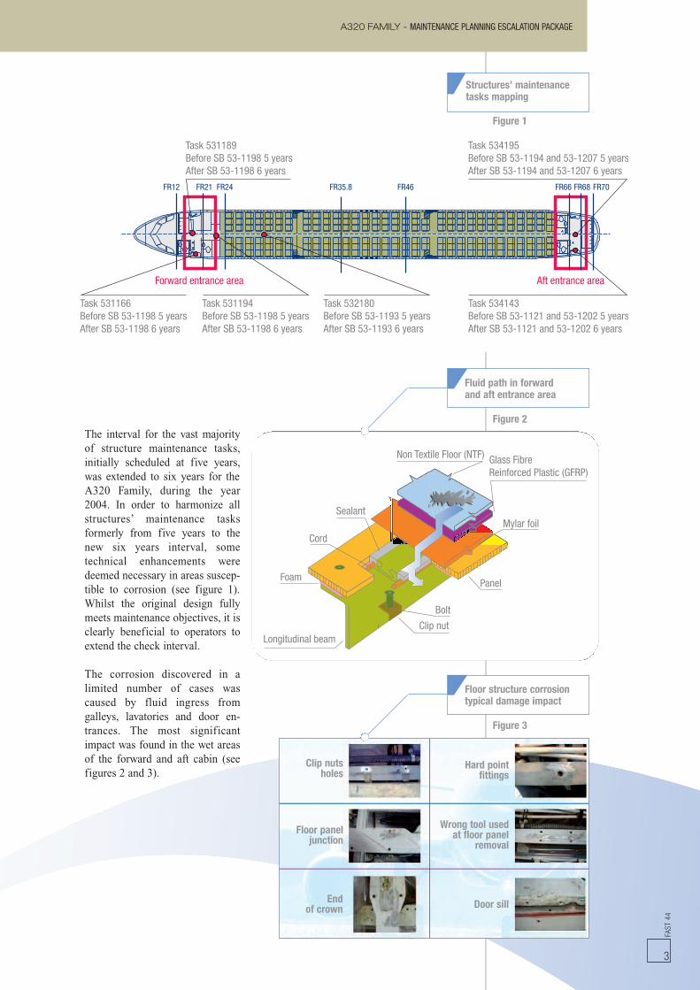
Task 534195Before SB 53-1194 and 53-1207 5 yearsAfter SB 53-1194 and 53-1207 6 years
Task 534143Before SB 53-1121 and 53-1202 5 yearsAfter SB 53-1121 and 53-1202 6 years
Task 532180Before SB 53-1193 5 yearsAfter SB 53-1193 6 years
Task 531194Before SB 53-1198 5 yearsAfter SB 53-1198 6 years
Forward entrance area Aft entrance area
Task 531166Before SB 53-1198 5 yearsAfter SB 53-1198 6 years
Task 531189Before SB 53-1198 5 yearsAfter SB 53-1198 6 years
FR12 FR21 FR24 FR35.8 FR46 FR66 FR68 FR70
Non Textile Floor (NTF)
Sealant
Glass FibreReinforced Plastic (GFRP)
Mylar foil
Panel
Bolt
Clip nutLongitudinal beam
Foam
Cord
Figure 2The interval for the vast majorityof structure maintenance tasks,initially scheduled at five years,was extended to six years for theA320 Family, during the year2004. In order to harmonize allstructures’ maintenance tasksformerly from five years to thenew six years interval, sometechnical enhancements weredeemed necessary in areas suscep-tible to corrosion (see figure 1).Whilst the original design fullymeets maintenance objectives, it isclearly beneficial to operators toextend the check interval.
The corrosion discovered in alimited number of cases wascaused by fluid ingress fromgalleys, lavatories and door en-trances. The most significantimpact was found in the wet areasof the forward and aft cabin (seefigures 2 and 3).
Fluid path in forwardand aft entrance area
Figure 1
FAST
44
3
Clip nutsholes
Hard pointfittings
Floor paneljunction
Wrong tool usedat floor panel
removal
Endof crown Door sill
Structures’ maintenancetasks mapping
Figure 3
Floor structure corrosiontypical damage impact
A320 FAMILY - MAINTENANCE PLANNING ESCALATION PACKAGEFA
ST44
4
As ‘gaining access’ to the impactedarea and performing the job iscostly in terms of embodimenttime, installation during the heavymaintenance check is stronglyadvised to avoid unnecessarydowntime.
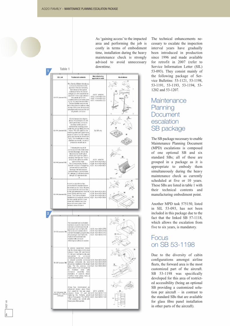
The technical enhancements ne-cessary to escalate the inspectioninterval years have graduallybeen introduced in productionsince 1996 and made availablefor retrofit in 2007 (refer toService Information Letter (SIL)53-093). They consist mainly ofthe following package of Ser-vice Bulletins: 53-1121, 53-1198,53-1191, 53-1193, 53-1194, 53-1202 and 53-1207.
MaintenancePlanningDocumentescalationSB packageThe SB package necessary to enableMaintenance Planning Document(MPD) escalations is composedof one optional SB and sixstandard SBs; all of these aregrouped in a package as it isappropriate to embody themsimultaneously during the heavymaintenance check as currentlyscheduled at five or 10 years.These SBs are listed in table 1 withtheir technical contents andmanufacturing embodiment point.
Another MPD task 575150, listedin SIL 53-093, has not beenincluded in this package due to thefact that the linked SB 57-1118,which allows the escalation fromfive to six years, is mandatory.
Focuson SB 53-1198Due to the diversity of cabinconfigurations amongst airlinefleets, the forward area is the mostcustomized part of the aircraft.SB 53-1198 was specificallydeveloped for this area of restrict-ed accessibility (being an optionalSB providing a customized solu-tion per aircraft – in contrast tothe standard SBs that are availablefor glass fibre panel installationin other parts of the aircraft).
1
2
Table 1
FAST
44
5
A320 FAMILY - MAINTENANCE PLANNING ESCALATION PACKAGE
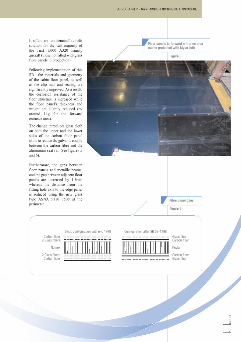
It offers an ‘on demand’ retrofitsolution for the vast majority ofthe first 1,000 A320 Familyaircraft (those not fitted with glassfibre panels in production).
Following implementation of thisSB , the materials and geometryof the cabin floor panel, as wellas the clip nuts and sealing aresignificantly improved. As a result,the corrosion resistance of thefloor structure is increased whilethe floor panel’s thickness andweight are slightly reduced (byaround 1kg for the forwardentrance area).
The change introduces glass clothon both the upper and the lowersides of the carbon floor panelskins to reduce the galvanic couplebetween the carbon fibre and thealuminium seat rail (see figures 5and 6).
Furthermore, the gaps betweenfloor panels and metallic beams,and the gap between adjacent floorpanels are increased by 1.5mmwhereas the distance from thefitting hole axis to the edge panelis reduced using the new glasstype ASNA 5110 7508 at theperimeter.
Floor panels in forward entrance area(some protected with Mylar foil)
Figure 5
Figure 6
Basic configuration until end 1999 Configuration after SB 53-1198Glass fiberCarbon fiber
Kevlar
Carbon fiberGlass fiber
Carbon fiber2 Glass fibers
Nomex
2 Glass fibersCarbon fiber
Fibre panel plies
Glass protection 3MChord NAS3811-D
Seat trackNew sealant (more fluid)
New floor panel
AJ
A320 FAMILY - MAINTENANCE PLANNING ESCALATION PACKAGEFA
ST44
6
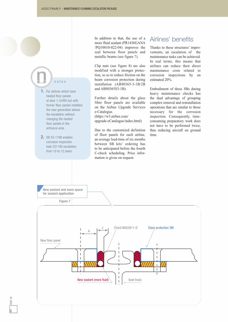
In addition to that, the use of amore fluid sealant (PR1436GANA/PQ10010-022-04) improves theseal between floor panels andmetallic beams (see figure 7).
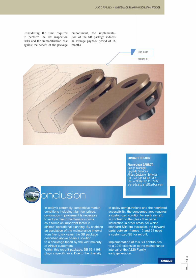
Clip nuts (see figure 8) are alsomodified with a stronger protec-tion, so as to reduce friction on thebeam corrosion protection duringinstallation (ABS0365-3-1B/2Band ABS0365S3-1B).
Further details about the glassfibre floor panels are availableon the Airbus Upgrade Servicese-Catalogue.(https://w3.airbus.com/upgrade-eCatalogue/index.html)
Due to the customized definitionof floor panels for each airline,an average lead-time of six monthsbetween SB kits’ ordering hasto be anticipated before the fourthC-check scheduling. Price infor-mation is given on request.
Airlines’ benefitsThanks to these structures’ impro-vements, an escalation of themaintenance tasks can be achieved.In real terms, this means thatairlines can reduce their directmaintenance costs related tocorrosion inspections by anestimated 20%.
Embodiment of these SBs duringheavy maintenance checks hasthe dual advantage of groupingcomplex removal and reinstallationoperations that are similar to thosenecessary for the corrosioninspection. Consequently, time-consuming preparatory work doesnot have to be performed twice,thus reducing aircraft on groundtime.
New sealant and more spacefor sealant application
n o t e s
1. For airlines which haveheated floor panelsat door 1 LH/RH but withformer floor panels installed,the new generation allowsthe escalation withoutchanging the heatedfloor panels in theentrance area.
2. SB 53-1198 enablescorrosion inspectiontask 531190 escalationfrom 10 to 12 years.
Figure 7
Considering the time requiredto perform the six inspectiontasks and the immobilisation costagainst the benefit of the package
embodiment, the implementa-tion of the SB package inducesan average payback period of 16months.
7
FAST
44
7
In today’s extremely competitive marketconditions including high fuel prices,continuous improvement is necessaryto reduce direct maintenance costsas it forms an important factor inairlines’ operational planning. By enablingan escalation of the maintenance intervalfrom five to six years, the SB packagedescribed above offers a solutionto a challenge faced by the vast majorityof Airbus customers.Within this retrofit package, SB 53-1198plays a specific role. Due to the diversity
of galley configurations and the restrictedaccessibility, the concerned area requiresa customized solution for each aircraft.In contrast to the glass fibre panelinstallation in other areas (for whichstandard SBs are available), the forwardparts between frames 12 and 24 needa customized SB for retrofit.
Implementation of this SB contributesto a 20% extension to the maintenanceinterval of the A320 Familyearly generation.
Conclusion
CONTACT DETAILS
Pierre-Jean GARROTDesign ManagerUpgrade ServicesAirbus Customer ServicesTel: +33 (0)5 61 93 28 71Fax: +33 (0)5 62 11 03 [email protected]
A320 FAMILY - MAINTENANCE PLANNING ESCALATION PACKAGE
Figure 8
Clip nuts
FUEL TANK INERTING SYSTEM - A RETROFIT INDUSTRIAL CHALLENGEFA
ST44
8
Alain LEROUXHead of Multi-Programme
and Business ConsolidationAirbus Customer Services
Sammy BOUGACIFuel Systems Engineer
Airbus Customer Services
Laurent SEGUYFuel Systems EngineerAirbus Customer Services
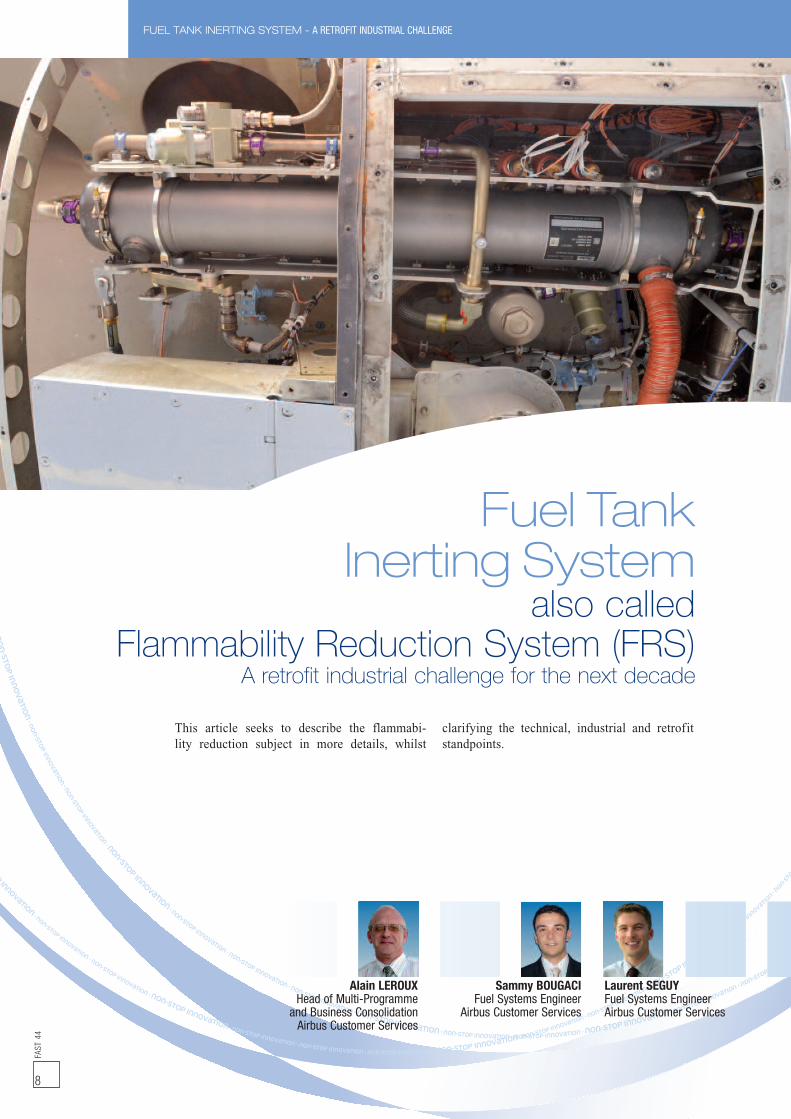
Fuel TankInerting System
also calledFlammability Reduction System (FRS)
A retrofit industrial challenge for the next decade
This article seeks to describe the flammabi-lity reduction subject in more details, whilst
clarifying the technical, industrial and retrofitstandpoints.
FAST
44
9
FUEL TANK INERTING SYSTEM - A RETROFIT INDUSTRIAL CHALLENGE
BackgroundAs a result of a major accidentresulting from a fuel tank explosion,in 1996 the Federal AviationAuthority (FAA) Technical Centreundertook researches into fuel tankflammability and ignition risks.Since 2000, Airbus has activelybeen involved in flammabilityreduction, conducting studies forthe FAA and flight tests on theA320 prototype in 2003.
As a result of these researches,the FAA has developed a rulethat requires operators and manu-facturers of air transportationcategories to take actions that willreduce the exposure to catastrophicfuel tank explosion.
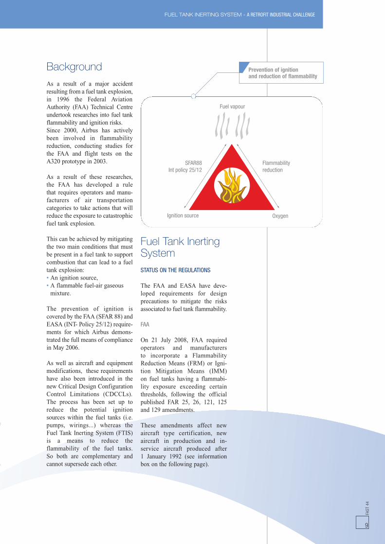
This can be achieved by mitigatingthe two main conditions that mustbe present in a fuel tank to supportcombustion that can lead to a fueltank explosion:• An ignition source,• A flammable fuel-air gaseousmixture.
The prevention of ignition iscovered by the FAA (SFAR 88) andEASA (INT- Policy 25/12) require-ments for which Airbus demons-trated the full means of compliancein May 2006.
As well as aircraft and equipmentmodifications, these requirementshave also been introduced in thenew Critical Design ConfigurationControl Limitations (CDCCLs).The process has been set up toreduce the potential ignitionsources within the fuel tanks (i.e.pumps, wirings...) whereas theFuel Tank Inerting System (FTIS)is a means to reduce theflammability of the fuel tanks.So both are complementary andcannot supersede each other.
Fuel Tank InertingSystemSTATUS ON THE REGULATIONS
The FAA and EASA have deve-loped requirements for designprecautions to mitigate the risksassociated to fuel tank flammability.
FAA
On 21 July 2008, FAA requiredoperators and manufacturersto incorporate a FlammabilityReduction Means (FRM) or Igni-tion Mitigation Means (IMM)on fuel tanks having a flammabi-lity exposure exceeding certainthresholds, following the officialpublished FAR 25, 26, 121, 125and 129 amendments.
These amendments affect newaircraft type certification, newaircraft in production and in-service aircraft produced after1 January 1992 (see informationbox on the following page).
Fuel vapour
Flammabilityreduction
SFAR88Int policy 25/12
Ignition source Oxygen
Prevention of ignitionand reduction of flammability
FUEL TANK INERTING SYSTEM - A RETROFIT INDUSTRIAL CHALLENGE
EASA
For new aircraft, EASA (EuropeanAviation Safety Agency) haveissued for consultation a draftamendment to CS-25 (NPA 2008-19) which is harmonized with thecorresponding American standard(FAR 25). A final decision isexpected by the 2nd quarter of 2009.
For in-production and in-serviceaircraft, EASA have stated theywill publish in 2009 a NPA to CS–26 and a Safety Directive to beadopted by the 4th quarter of 2010after taking into account thereceived comments.
AIRBUS COMPLIANCE TO THE RULES
Airbus demonstrated that ‘onlythe centre tank’ of some of itsexisting aircraft has fleet averageflammability exposure exceeding7% and is affected by therequirements of the FAR Part 26.There is no necessity to do anymodification on other tanks.It concerns the following aircraft:• A320 Family,• A330-200, A340-200,A340-300, A340-500, A340-600,
• A300-600.
At the date of publishing, the rulesapply only for passenger aircraftproduced and delivered after1 January 1992 flying with USoperators or N-registered passengeraircraft.
SYSTEM DESCRIPTION
The Airbus solution for the A320Family and A330/A340 Family isbased on a system developed withthe supplier, Parker, which reducesthe oxygen levels of the centre tankullage space.
The installation of this new deviceis designed to avoid themodification of existing systemsand structures. The Fuel TankInerting System (FTIS) interfaceswith the following systems:• Fuel systems,• Environmental Control Systems,• Engine bleed air supply systems.
Several other alternate means havebeen studied (e.g. reduction of heatsources, tank pressurisation andfoam). But they lead either toimportant structure modificationsor operational constraints.
One solution studied was to usebottled nitrogen, but it was dis-missed due to the significantrequired additional airport infras-tructure and the impact on aircraftTurn Around Time (TAT).
FAST
44
10
n o t e s
• Existing freighter aircraft orpassenger to freighter convertedaircraft are not involved.
• For the A300-600 aircraft,no more N-registeredpassenger aircraft will beoperated at the time of the FAAdeadlines for the retrofitcompletion. If the FlammabilityReduction Means (FRM)is required by any localAirworthiness Authoritiesas the fleet averageflammability exposure near 7%,a modification basedon a cooling concept of thecentre tank will be proposed.
i n f o r m a t i o n
• FAR Part 25: Amendment 125It will be the certification basisfor new aircraft types. It updates§ 25.981 by including the flammabilitycriteria and means to be met by thetanks, the IMM requirements, theinstruction for ContinuedAirworthiness. It defines themethodology to be used to performthe fuel tank flammability analysis,
• FAR Part 26: Amendment 3This amendment is applicableto existing Type Certificates (TC)including Supplemental TypeCertificates (STC). It requiresfor passenger aircraft of 30or more seats manufacturedon/or after January 1st, 1992:- to submit to FAA by Feb 16th, 2009.
A flammability analysis for eachtank as per FAR Part 25 appendix N,
- to provide a FRM or IMM for tankshaving a fleet average flammabilityexposure exceeding 7%,
- to submit the required FRM/IMMchanges and associated ServiceInstructions for approvalby Dec 26th 2010,
• FAR Part 121: Amendment 340It applies to US operators whateverthe country of registrationof the aircraft used by theseoperators. It sets requirementsfor retrofit of passenger aircraftwith a Flammability Reduction Means(FRM) or an Ignition Mitigation Means(IMM) if required per FAR Part 26.The retrofit shall be completedat the latest by December 2017with an intermediate requirementto retrofit half of the operator fleetby December 2014. New aircraftdelivered to an operator afterDecember 26th, 2010 must be fittedwith an operational FRM or IMM,
• FAR Part 125: Amendment 55Similar requirements to those of FARPart 121 applied for specific typeof commercial passenger carryingoperations,
• FAR Part 129: Amendment 46Similar requirements to thoseof FAR Part 121 applied for foreignoperators of aircraft registeredin the United States.
FAA ruling requirements (summary)
FAST
44
11
SYSTEM INSTALLATIONON AIRCRAFT
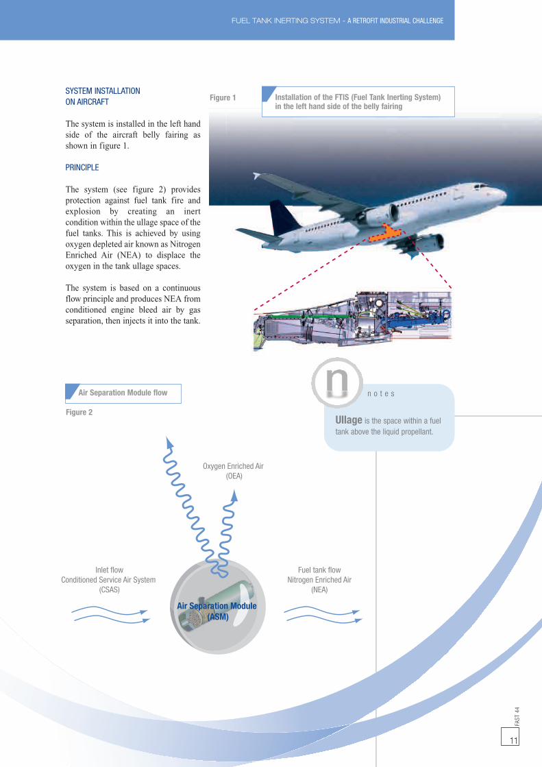
The system is installed in the left handside of the aircraft belly fairing asshown in figure 1.
PRINCIPLE
The system (see figure 2) providesprotection against fuel tank fire andexplosion by creating an inertcondition within the ullage space of thefuel tanks. This is achieved by usingoxygen depleted air known as NitrogenEnriched Air (NEA) to displace theoxygen in the tank ullage spaces.
The system is based on a continuousflow principle and produces NEA fromconditioned engine bleed air by gasseparation, then injects it into the tank.
FUEL TANK INERTING SYSTEM - A RETROFIT INDUSTRIAL CHALLENGE
Air Separation Module(ASM)
Inlet flowConditioned Service Air System
(CSAS)
Oxygen Enriched Air(OEA)
Fuel tank flowNitrogen Enriched Air
(NEA)
Figure 2
Air Separation Module flow
Installation of the FTIS (Fuel Tank Inerting System)in the left hand side of the belly fairing
Figure 1
n o t e s
Ullage is the space within a fueltank above the liquid propellant.
FUEL TANK INERTING SYSTEM - A RETROFIT INDUSTRIAL CHALLENGEFA
ST44
12
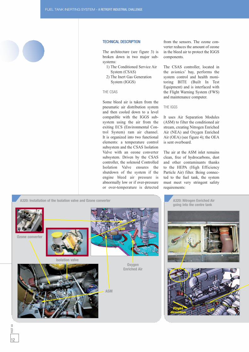
TECHNICAL DESCRIPTION
The architecture (see figure 3) isbroken down in two major sub-systems:
1) The Conditioned Service AirSystem (CSAS)
2) The Inert Gas GenerationSystem (IGGS)
THE CSAS
Some bleed air is taken from thepneumatic air distribution systemand then cooled down to a levelcompatible with the IGGS sub-system using the air from theexiting ECS (Environmental Con-trol System) ram air channel.It is organized into two functionalelements: a temperature controlsubsystem and the CSAS IsolationValve with an ozone convertersubsystem. Driven by the CSAScontroller, the solenoid ControlledIsolation Valve ensures theshutdown of the system if theengine bleed air pressure isabnormally low or if over-pressureor over-temperature is detected
from the sensors. The ozone con-verter reduces the amount of ozonein the bleed air to protect the IGGScomponents.
The CSAS controller, located inthe avionics’ bay, performs thesystem control and health moni-toring BITE (Built In TestEquipment) and is interfaced withthe Flight Warning System (FWS)and maintenance computer.
THE IGGS
It uses Air Separation Modules(ASM) to filter the conditioned airstream, creating Nitrogen EnrichedAir (NEA) and Oxygen EnrichedAir (OEA) (see figure 4); the OEAis sent overboard.
The air at the ASM inlet remainsclean, free of hydrocarbons, dustand other contaminants thanksto the HEPA (High EfficiencyParticle Air) filter. Being connec-ted to the fuel tank, the systemmust meet very stringent safetyrequirements:
Isolation valve
Ozone converter
ASM
OxygenEnriched Air
C35
A320: Installation of the Isolation valve and Ozone converter A320: Nitrogen Enriched Airgoing into the centre tank
C36
C35Flightdirection
NitrogenEnriched Air
ProductO2 RichWaste
O2 CO2H2O
Air
NEA
13
FUEL TANK INERTING SYSTEM - A RETROFIT INDUSTRIAL CHALLENGE
FAST
44
Twin check valve
Centretank
Dual Flow ShutOff Valve
Pallet
O2sensor
Air separationmodule
Waste flow(O2 rich)Overboard exit
Heatexchanger TCM
Tempcontrolvalve
HEPAfilter
SensorsSensors
IGGS controllerCSAS controllerFWCCFDIU/CMC
Bleed line
Isolationvalve
O3 converter
Figure 3
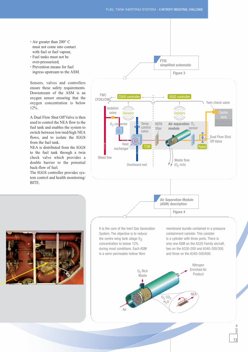
It is the core of the Inert Gas GenerationSystem. The objective is to reducethe centre wing tank ullage O2concentration to below 12%during most conditions. Each ASMis a semi-permeable hollow fibre
membrane bundle contained in a pressurecontainment canister. This canisteris a cylinder with three ports. There isonly one ASM on the A320 Family aircraft,two on the A330-200 and A340-200/300,and three on the A340-500/600.
• Air greater than 200° Cmust not come into contactwith fuel or fuel vapour,
• Fuel tanks must not beover-pressurized,
• Prevention means for fuelingress upstream to the ASM.
Sensors, valves and controllersensure these safety requirements.Downstream of the ASM is anoxygen sensor ensuring that theoxygen concentration is below12%.
A Dual Flow Shut Off Valve is thenused to control the NEA flow to thefuel tank and enables the system toswitch between low/mid/high NEAflows, and to isolate the IGGSfrom the fuel tank.NEA is distributed from the IGGSto the fuel tank through a twincheck valve which provides adouble barrier to the potentialback-flow of fuel.The IGGS controller provides sys-tem control and health monitoring/BITE.
FTISsimplified schematic
Figure 4
Air Separation Module(ASM) description
FAST
44
14
FTIS operationThe Fuel Tank Inerting System(FTIS) operates during flight whenthe bleed air is supplied. The systemdoes not operate when the aircraft ison the ground, except duringmaintenance operations.
It has three flow modes designed toachieve the flammability reductionobjective during the different flightphases:• Low is used in climband cruise,
• Medium is used in approachand slow descent,
• High is used in descent.
The FTIS will not be operationalwhen either the electrical power orthe bleed are unavailable, nor whenthe anti-ice is ON with a non-operating engine (i.e. A330).
OPERATIONAL IMPACTS
The FTIS has automatic controlwith no requirement for crewintervention.
Any system fault leading to the lossof inerting capability generates acockpit and maintenance messageat the end of the flight (flight phase10) for maintenance purposes:• For A320 Family a maintenanceSTATUS: ‘INERT FAULT’,
• For A330/A340 Familyan ECAM message: ‘FUELINERTING SYS FAULT’.
The aircraft can be dispatched underMinimum Equipment List (MEL)with the system inoperative during10 days with no specific maintenanceaction.
The implementation of these newcockpit and fault messages requiresupgraded standards of the FlightWarning Computers (FWC) andmaintenance computers (CFDIUfor the A320 Family, CMC forthe A330/A340 Family) (seeinformation note).
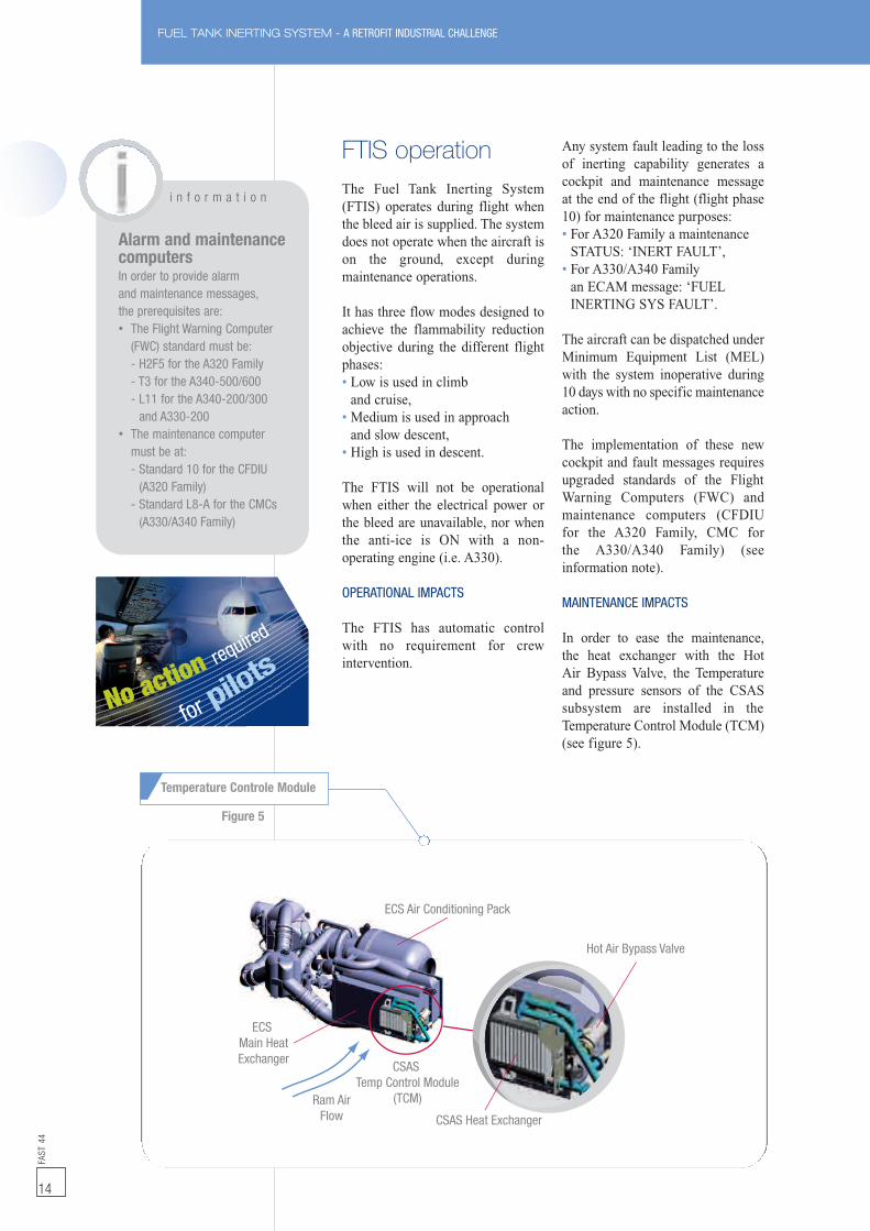
MAINTENANCE IMPACTS
In order to ease the maintenance,the heat exchanger with the HotAir Bypass Valve, the Temperatureand pressure sensors of the CSASsubsystem are installed in theTemperature Control Module (TCM)(see figure 5).
FUEL TANK INERTING SYSTEM - A RETROFIT INDUSTRIAL CHALLENGE
ECS Air Conditioning Pack
ECSMain HeatExchanger
Hot Air Bypass Valve
CSAS Heat Exchanger
CSASTemp Control Module
(TCM)Ram AirFlow
No action required
for pilots
i n f o r m a t i o n
Alarm and maintenancecomputersIn order to provide alarmand maintenance messages,the prerequisites are:• The Flight Warning Computer
(FWC) standard must be:- H2F5 for the A320 Family- T3 for the A340-500/600- L11 for the A340-200/300
and A330-200• The maintenance computer
must be at:- Standard 10 for the CFDIU
(A320 Family)- Standard L8-A for the CMCs
(A330/A340 Family)
Figure 5
Temperature Controle Module
FAST
44
15
FUEL TANK INERTING SYSTEM - A RETROFIT INDUSTRIAL CHALLENGE
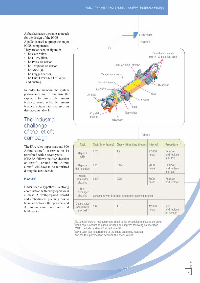
Airbus has taken the same approachfor the design of the IGGS.A pallet is used to group the majorIGGS components.They are as seen in figure 6:• The Gate Valve,• The HEPA filter,• The Pressure sensor,• The Temperature sensor,• The ASM (s),• The Oxygen sensor,• The Dual Flow Shut Off Valveand ducting.
In order to maintain the systemperformance and to minimize theexposure to unscheduled main-tenance, some scheduled main-tenance actions are required asdescribed in table 1.
The industrialchallengeof the retrofitcampaignThe FAA rules impacts around 900Airbus aircraft in-service to beretrofitted within seven years.If EASA follows the FAA decisionon retrofit, around 4500 Airbusaircraft will have to be retrofittedduring the next decade.
PLANNING
Under such a hypothesis, a strongcoordination with every operator isa must. A well-prepared retrofitand embodiment planning has tobe set up between the operators andAirbus to avoid any industrialbottlenecks.
Tie rod attachments(MS14103 Spherical Brg.)
O2 sensor
ASM
NEA outlet
filter
Nameplate
OEA outlet
Aft palletbracket
Air inlet
Gate valve
Pressure sensor
Temperature sensor
Dual Flow Shut Off Valve
1 No special tools or test equipment required for scheduled maintenance tasks2 Drain cap is opened to check for liquid fuel ingress following no operationMMEL periods or after a fuel tank overfill
3 Valve Leak test is performed at the liquid drain plug locationand the test port location between the check valves
Task Task time (hours) Check labor time (hours) Interval Procedure 1 2
0.75 1.2 27,000 Removehours and replace,
leak test
0.28 0.45 7000 Removehours and replace,
leak test
0.58 0.75 6000 Removehours and replace
Consistent with ECS heat exchanger cleaning interval
1.0 1.5 12,000 Testhours and replace
as needed
ReplaceASM
Replacefilter element
OzoneConvertercleaning
HeatExchangercleaning
Check valveand DFSOVLeak test 3
Table 1
IGGS Pallet
Figure 6
FUEL TANK INERTING SYSTEM - A RETROFIT INDUSTRIAL CHALLENGEFA
ST44
16
AIRBUS RETROFIT OFFER
Airbus Upgrade Services throughthe RFC/RMO process will provi-de customized commercial andtechnical services consisting of aretrofit package with:• Two Service Bulletins:
- One SBfor the structuraland electrical provisions,
- One SBfor the equipment installationallowing the customerto complete the retrofitin packages during C-checks,
• Airbus kits (brackets, pipes,rods, wiring, etc.),
• Specific FTIS equipmentfrom Parker and Liebherr,
• The coordination of the kitand equipment deliveries.
Flight Warning Computers andmaintenance computers’ standardsshould accept messages provided bythe FTIS (see information for therequested corresponding standards).Upon request, technical support onsite can be provided. Airbus willalso provide relevant trainingcourses to your maintenance staff.
EMBODIMENT ON AIRCRAFT
About 500 man-hours are neededwith a lead-time of 7/8 days ifdone in one operation (provisionsand installation). This takes intoaccount the aircraft preparation(scaffolding, centre tank ventingand all the tests). The work can bedone in two packages (provi-sions, then equipment installation)allowing the operator to performthe modification within twoC-checks.
g l o s s a r y
ASM: Air Separation ModuleBITE: Built In Test EquipmentCFDIU: Centralised Fault DisplayInterface UnitCMC: Centralised MaintenanceComputerCSAS: Conditioned Service AirSystemDFSOV: Dual Flow Shut Off ValveEASA: European Aviation SafetyAgencyECS: Environmental Control SystemFAA: Federal AviationAdministrationFAR: Federal Aviation RegulationsFRM: Flammability reduction MeanFTIS: Fuel Tank Inerting SystemFWC: Flight Warning ComputerHEPA: High Efficiency Particle AirIGGS: Inert Gas Generation SystemIMM: Ignition Mitigation MeanMEL: Minimum Equipment ListNEA: Nitrogen Enriched AirNPA: Notice for ProposedAmendmentOEA: Oxygen Enriched AirRFC/RMO: Request For Change/Retrofit Modification OfferSTC: Supplemental type CertificateTC: Type Certificate
i n f o r m a t i o n
Airbus documentation• SFAR 88: S.I.L. 28-072
Fuel tank protection againstignition source,
• FTIS: OIT 999.0007/06ATA28-FAA NPRM on flammabilityreduction system retrofit,
• FTIS: OIT 999.0084/08ATA47-FAA flammability,reduction system introduction
• AirbusWorld portal: dedicatedpage ‘Comply with Fuel TankSafety’.
To comply with the FAA flammabilityreduction rules, Airbus have developedthe most cost effective technicalcompromise in terms of maintenanceand operations. Airbus is fully committedin supporting the operators with thesenew requirements taking into account
the deadlines set up by the authorities.This can only be achievedwith the cooperation of the concernedoperators that will overcome thischallenging embodiment of the Fuel TankInerting System technology by schedulingthe installation in due time.
Conclusion
CONTACT DETAILS
RFC/RMO [email protected]
Technical queriesRonan ALLARDDesign ManagerUpgrade ServicesAirbus Customer ServicesTel: +33 (0)5 62 11 07 73Fax: +33 (0)5 62 11 08 [email protected]
FAST
44
17
BRAKE-TO-VACATE SYSTEM - THE SMART AUTOMATIC BRAKING SYSTEM
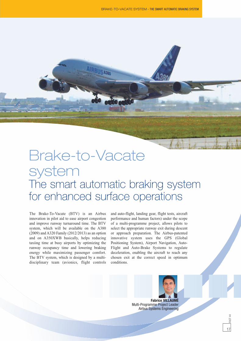
Fabrice VILLAUMÉMulti-Programme Project Leader
Airbus Systems Engineering
The Brake-To-Vacate (BTV) is an Airbusinnovation in pilot aid to ease airport congestionand improve runway turnaround time. The BTVsystem, which will be available on the A380(2009) and A320 Family (2012/2013) as an optionand on A350XWB basically, helps reducingtaxiing time at busy airports by optimizing therunway occupancy time and lowering brakingenergy while maximizing passenger comfort.The BTV system, which is designed by a multi-disciplinary team (avionics, flight controls
and auto-flight, landing gear, flight tests, aircraftperformance and human factors) under the scopeof a multi-programme project, allows pilots toselect the appropriate runway exit during descentor approach preparation. The Airbus-patentedinnovative system uses the GPS (GlobalPositioning System), Airport Navigation, Auto-Flight and Auto-Brake Systems to regulatedeceleration, enabling the aircraft to reach anychosen exit at the correct speed in optimumconditions.
Brake-to-VacatesystemThe smart automatic braking systemfor enhanced surface operations
BRAKE-TO-VACATE SYSTEM - THE SMART AUTOMATIC BRAKING SYSTEMFA
ST44
18
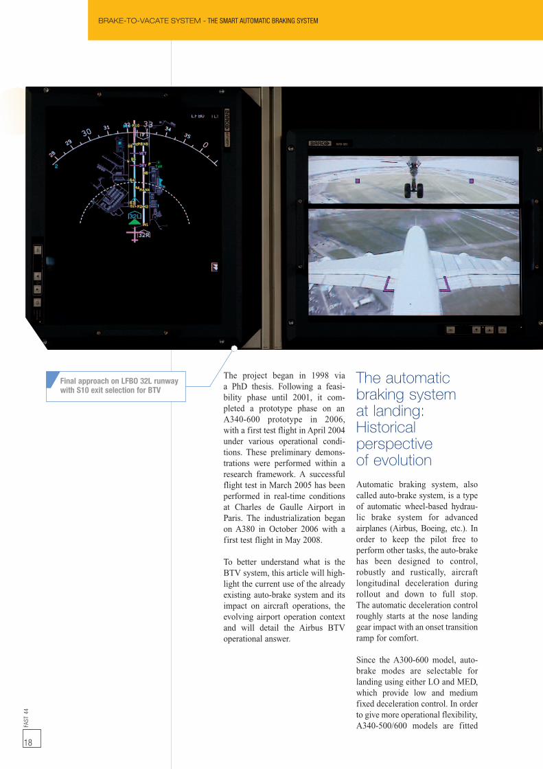
The project began in 1998 viaa PhD thesis. Following a feasi-bility phase until 2001, it com-pleted a prototype phase on anA340-600 prototype in 2006,with a first test flight in April 2004under various operational condi-tions. These preliminary demons-trations were performed within aresearch framework. A successfulflight test in March 2005 has beenperformed in real-time conditionsat Charles de Gaulle Airport inParis. The industrialization beganon A380 in October 2006 with afirst test flight in May 2008.
To better understand what is theBTV system, this article will high-light the current use of the alreadyexisting auto-brake system and itsimpact on aircraft operations, theevolving airport operation contextand will detail the Airbus BTVoperational answer.
The automaticbraking systemat landing:Historicalperspectiveof evolutionAutomatic braking system, alsocalled auto-brake system, is a typeof automatic wheel-based hydrau-lic brake system for advancedairplanes (Airbus, Boeing, etc.). Inorder to keep the pilot free toperform other tasks, the auto-brakehas been designed to control,robustly and rustically, aircraftlongitudinal deceleration duringrollout and down to full stop.The automatic deceleration controlroughly starts at the nose landinggear impact with an onset transitionramp for comfort.
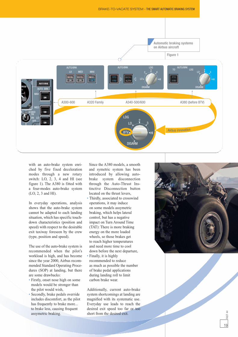
Since the A300-600 model, auto-brake modes are selectable forlanding using either LO and MED,which provide low and mediumfixed deceleration control. In orderto give more operational flexibility,A340-500/600 models are fitted
Final approach on LFBO 32L runwaywith S10 exit selection for BTV
FAST
44
19
BRAKE-TO-VACATE SYSTEM - THE SMART AUTOMATIC BRAKING SYSTEM
with an auto-brake system enri-ched by five fixed decelerationmodes through a new rotaryswitch: LO, 2, 3, 4 and HI (seefigure 1). The A380 is fitted witha four-modes auto-brake system(LO, 2, 3 and HI).
In everyday operations, analysisshows that the auto-brake systemcannot be adapted to each landingsituation, which has specific touch-down characteristics (position andspeed) with respect to the desirableexit taxiway foreseen by the crew(type, position and speed).
The use of the auto-brake system isrecommended when the pilot’sworkload is high, and has becomesince the year 2000, Airbus recom-mended Standard Operating Proce-dures (SOP) at landing, but thereare some drawbacks:• Firstly, onset nose high on somemodels would be stronger thanthe pilot would wish,
• Secondly, brake pedals overrideincludes discomfort, as the pilothas frequently to brake more...to brake less, causing frequentassymetric braking.
Since the A380 models, a smoothand symetric system has beenintroduced by allowing auto-brake system disconnectionthrough the Auto-Thrust Ins-tinctive Disconnection buttonlocated on the thrust levers,
• Thirdly, associated to crosswindoperations, it may induceon some models assymetricbraking, which helps lateralcontrol, but has a negativeimpact on Turn Around Time(TAT): There is more brakingenergy on the more loadedwheels, so those brakes getto reach higher temperaturesand need more time to cooldown before the next departure,
• Finally, it is highlyrecommended to reduceas much as possible the numberof brake pedal applicationsduring landing roll to limitcarbon brake wear.
Additionally, current auto-brakesystem shortcomings at landing aremagnified with its systematic use.Everyday use leads to reach thedesired exit speed too far or tooshort from the desired exit.
OFFLO
MED
MAX
AUTO BRK
ONON
K A/SKID
Airbus innovation
A300-600 A320 Family A340-500/600 A380 (before BTV)
HI
43
2
LO
DISARM
AUTO/BRK LDGAUTO/BRK
L0 MED MAX
HI
32
LO
DISARM
AUTO/BRKLDGTO
HI
32
LO
BTV
LDG
DISARM
Figure 1
Automatic braking systemson Airbus aircraft
BRAKE-TO-VACATE SYSTEM - THE SMART AUTOMATIC BRAKING SYSTEMFA
ST44
20
i n f o r m a t i o n
Synthetically, currentauto-brake systemdrawbacks (induced by its usefulrusticity) are, in everyday avera-tions, an approximate optimizationachieved by the pilot (i.e. too highdeceleration followed by too longspeed taxi on the runway),a partial awareness of theestimated and measured brakingdistance, a lack of flexibilitywith respect to operational con-straints and an ‘Airport Navigation’unawareness.
GEO50XEXIT
XEXITGEO50
50 kts(0.3g)50 kts(0.2g)
50 kts(0.3g)50 kts(0.2g)
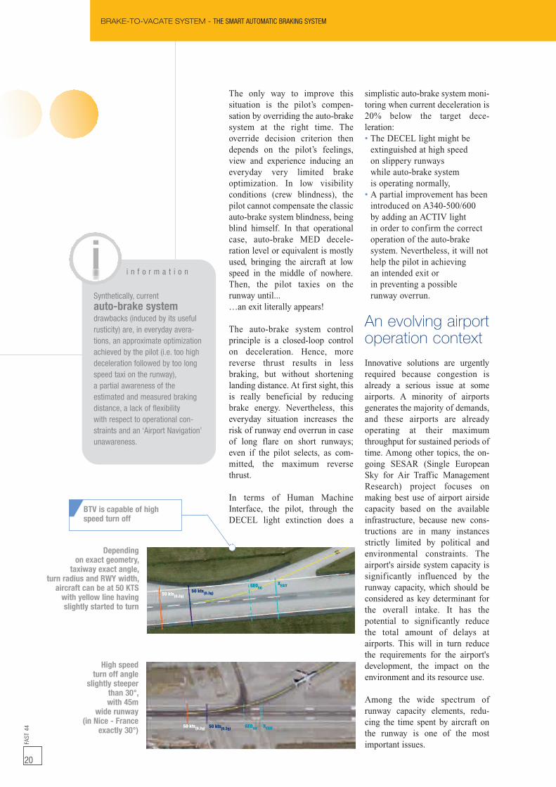
Dependingon exact geometry,taxiway exact angle,
turn radius and RWY width,aircraft can be at 50 KTSwith yellow line havingslightly started to turn
High speedturn off angleslightly steeper
than 30°,with 45m
wide runway(in Nice - France
exactly 30°)
The only way to improve thissituation is the pilot’s compen-sation by overriding the auto-brakesystem at the right time. Theoverride decision criterion thendepends on the pilot’s feelings,view and experience inducing aneveryday very limited brakeoptimization. In low visibilityconditions (crew blindness), thepilot cannot compensate the classicauto-brake system blindness, beingblind himself. In that operationalcase, auto-brake MED decele-ration level or equivalent is mostlyused, bringing the aircraft at lowspeed in the middle of nowhere.Then, the pilot taxies on therunway until...…an exit literally appears!
The auto-brake system controlprinciple is a closed-loop controlon deceleration. Hence, morereverse thrust results in lessbraking, but without shorteninglanding distance. At first sight, thisis really beneficial by reducingbrake energy. Nevertheless, thiseveryday situation increases therisk of runway end overrun in caseof long flare on short runways;even if the pilot selects, as com-mitted, the maximum reversethrust.
In terms of Human MachineInterface, the pilot, through theDECEL light extinction does a
simplistic auto-brake system moni-toring when current deceleration is20% below the target dece-leration:• The DECEL light might beextinguished at high speedon slippery runwayswhile auto-brake systemis operating normally,
• A partial improvement has beenintroduced on A340-500/600by adding an ACTIV lightin order to confirm the correctoperation of the auto-brakesystem. Nevertheless, it will nothelp the pilot in achievingan intended exit orin preventing a possiblerunway overrun.
An evolving airportoperation contextInnovative solutions are urgentlyrequired because congestion isalready a serious issue at someairports. A minority of airportsgenerates the majority of demands,and these airports are alreadyoperating at their maximumthroughput for sustained periods oftime. Among other topics, the on-going SESAR (Single EuropeanSky for Air Traffic ManagementResearch) project focuses onmaking best use of airport airsidecapacity based on the availableinfrastructure, because new cons-tructions are in many instancesstrictly limited by political andenvironmental constraints. Theairport's airside system capacity issignificantly influenced by therunway capacity, which should beconsidered as key determinant forthe overall intake. It has thepotential to significantly reducethe total amount of delays atairports. This will in turn reducethe requirements for the airport'sdevelopment, the impact on theenvironment and its resource use.
Among the wide spectrum ofrunway capacity elements, redu-cing the time spent by aircraft onthe runway is one of the mostimportant issues.
BTV is capable of highspeed turn off
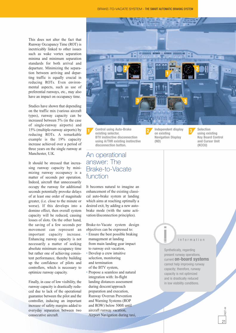
2 Independent displayon existingNavigation Display(ND)
FAST
44
21
This does not alter the fact thatRunway Occupancy Time (ROT) isinextricably linked to other issuessuch as wake vortex separationminima and minimum separationstandards for both arrival anddeparture. Minimizing the separa-tion between arriving and depar-ting traffic is equally crucial inreducing ROTs. Even environ-mental aspects, such as use ofpreferential runways, etc., may alsohave an impact on occupancy time.
Studies have shown that dependingon the traffic mix (various aircrafttypes), runway capacity can beincreased between 5% (in the caseof single-runway airports) and15% (multiple-runway airports) byreducing ROTs. A remarkableexample is the 19% capacityincrease achieved over a period ofthree years on the single runway atManchester, U.K.
It should be stressed that increa-sing runway capacity by mini-mizing runway occupancy is amatter of seconds per operation.Indeed, aircraft that unnecessarilyoccupy the runway for additionalseconds potentially provoke delaysof at least one order of magnitudegreater, (i.e. close to the minute orworse). If this develops into adomino effect, then overall systemcapacity will be reduced, causinglosses of slots. On the other hand,the saving of a few seconds permovement can represent animportant capacity increase.Enhancing runway capacity is notnecessarily a matter of seekingabsolute minimum occupancy timebut rather one of achieving consis-tent performance, thereby buildingup the confidence of pilots andcontrollers, which is necessary tooptimize runway capacity.
Finally, in case of low visibility, therunway capacity is drastically redu-ced due to lack of the operationalguarantee between the pilot and thecontroller, inducing an importantincrease of safety margins added toeveryday separation between twoconsecutive aircraft.
An operationalanswer: TheBrake-to-VacatefunctionIt becomes natural to imagine anenhancement of the existing classi-cal auto-brake system at landingwhich aims at reaching optimally adesired exit, by adding a new auto-brake mode (with the same acti-vation/disconnection principles).
Brake-to-Vacate system designobjectives can be expressed to:• Ensure the best possible brakingmanagement at landingfrom main landing gear impactto runway exit vacation,
• Develop a crew intuitiveselection, monitoringand terminationof the BTV system,
• Propose a seamless and naturalintegration with: In-flightlanding distances assessmentduring descent/approachpreparation and execution,Runway Overrun Preventionand Warning Systems (ROPand ROW) below 500ft untilaircraft runway vacation,Airport Navigation during taxi,
12 2
3 3
i n f o r m a t i o n
Synthetically, regardingpresent runway operations,current on-board systemscannot help improving runwaycapacity; therefore, runwaycapacity is not optimizedand is drastically reducedin low visibility conditions.
3 Selectionusing existingKey Board Controland Cursor Unit(KCCU)
BRAKE-TO-VACATE SYSTEM - THE SMART AUTOMATIC BRAKING SYSTEM
1 Control using Auto-Brakeexisting selector.BTV instinctive disconnectionusing A/THR existing instinctivedisconnection button.
2
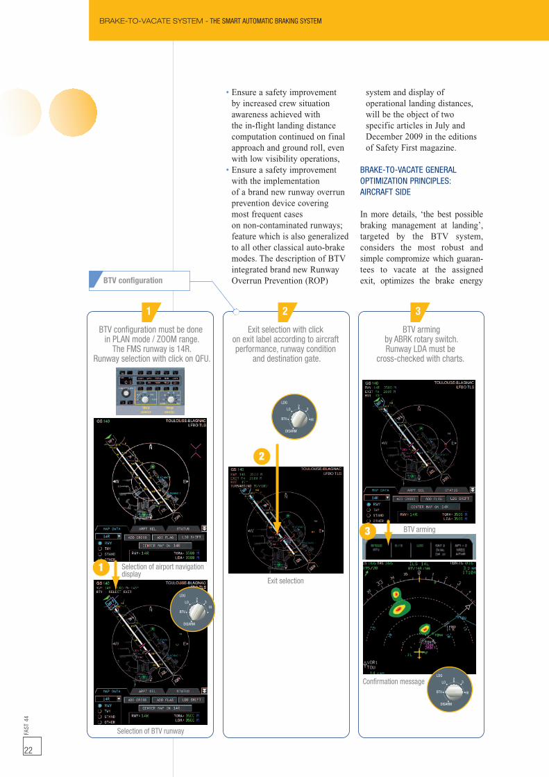
BTV configuration must be donein PLAN mode / ZOOM range.
The FMS runway is 14R.Runway selection with click on QFU.
Selection of airport navigationdisplay
BTV arming
Confirmation message
Selection of BTV runway
Exit selection
Exit selection with clickon exit label according to aircraftperformance, runway condition
and destination gate.
BTV armingby ABRK rotary switch.Runway LDA must be
cross-checked with charts.
1
1
2 3
HI3
2LO
BTV
LDG
DISARM
HI
32
LO
BTV
LDG
DISARM
HI
32
LO
BTV
LDG
DISARM
3
BRAKE-TO-VACATE SYSTEM - THE SMART AUTOMATIC BRAKING SYSTEMFA
ST44
22
• Ensure a safety improvementby increased crew situationawareness achieved withthe in-flight landing distancecomputation continued on finalapproach and ground roll, evenwith low visibility operations,
• Ensure a safety improvementwith the implementationof a brand new runway overrunprevention device coveringmost frequent caseson non-contaminated runways;feature which is also generalizedto all other classical auto-brakemodes. The description of BTVintegrated brand new RunwayOverrun Prevention (ROP)
system and display ofoperational landing distances,will be the object of twospecific articles in July andDecember 2009 in the editionsof Safety First magazine.
BRAKE-TO-VACATE GENERALOPTIMIZATION PRINCIPLES:AIRCRAFT SIDE
In more details, ‘the best possiblebraking management at landing’,targeted by the BTV system,considers the most robust andsimple compromize which guaran-tees to vacate at the assignedexit, optimizes the brake energyBTV configuration
FAST
44
23
BRAKE-TO-VACATE SYSTEM - THE SMART AUTOMATIC BRAKING SYSTEM
regarding the current operationalconstraints, minimizes the runwayoccupancy time and improves thepassenger comfort.
In an operation, the optimum exitselection depends on multiplecriteria and constraints that canonly be known in their fullcomplexity by the pilot and the airtraffic controller:• Optimum braking energy(complex as function of taxi,of requested Turn Around Time(TAT), of noise abatementprocedures preventing maximalreverse thrust usage out of safetyneeds),
• Minimum number of brakeapplications,
• Minimum runway occupancytime,
• Best exit for taxi duration.
A short exit selection can obviouslyproduce lower runway occupancytime than a far exit, but with higherbrake energy and Turn AroundTime. At the end, no automaticselection of the optimum exit ispossible.Then, for an exit selected by thepilot, the BTV system guaranteesthat simultaneously the lowestbrake energy and runway occupan-cy time are reached. For this,BTV system delays braking asmuch as possible, applies themaximum possible braking at thelatest possible time while reachingthe exit at suitable speed. But adesign compromize has been foundin order to respect the passengers’comfort constraints by fixingmaximum level of deceleration andvariation of deceleration over time,during the landing roll. Moreover,a special attention has been paidto the BTV deceleration profilecomputation regarding the visualperception of the pilot associatedto late braking in the case of aselected exit close to the runwayend.
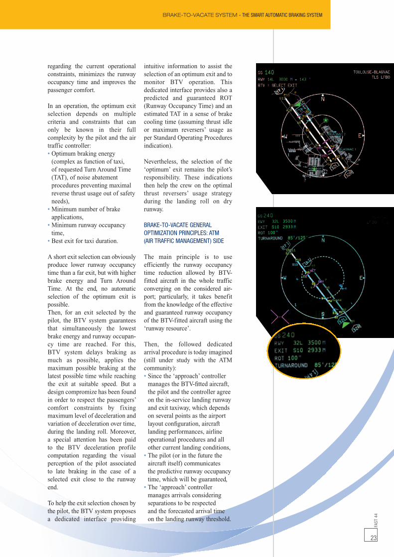
To help the exit selection chosen bythe pilot, the BTV system proposesa dedicated interface providing
intuitive information to assist theselection of an optimum exit and tomonitor BTV operation. Thisdedicated interface provides also apredicted and guaranteed ROT(Runway Occupancy Time) and anestimated TAT in a sense of brakecooling time (assuming thrust idleor maximum reversers’ usage asper Standard Operating Proceduresindication).
Nevertheless, the selection of the‘optimum’ exit remains the pilot’sresponsibility. These indicationsthen help the crew on the optimalthrust reversers’ usage strategyduring the landing roll on dryrunway.
BRAKE-TO-VACATE GENERALOPTIMIZATION PRINCIPLES: ATM(AIR TRAFFIC MANAGEMENT) SIDE
The main principle is to useefficiently the runway occupancytime reduction allowed by BTV-fitted aircraft in the whole trafficconverging on the considered air-port; particularly, it takes benefitfrom the knowledge of the effectiveand guaranteed runway occupancyof the BTV-fitted aircraft using the‘runway resource’.
Then, the followed dedicatedarrival procedure is today imagined(still under study with the ATMcommunity):• Since the ‘approach’ controllermanages the BTV-fitted aircraft,the pilot and the controller agreeon the in-service landing runwayand exit taxiway, which dependson several points as the airportlayout configuration, aircraftlanding performances, airlineoperational procedures and allother current landing conditions,
• The pilot (or in the future theaircraft itself) communicatesthe predictive runway occupancytime, which will be guaranteed,
• The ‘approach’ controllermanages arrivals consideringseparations to be respectedand the forecasted arrival timeon the landing runway threshold.
BRAKE-TO-VACATE SYSTEM - THE SMART AUTOMATIC BRAKING SYSTEMFA
ST44
24
The results of this sequencingtask is the location of all aircraftin final approach in orderto optimize the arrival flow withrespect to the runway occupancytime, but also allowable minimalseparations (radar and wakevortex). Also, it results inmanaging forecasted separationin time on a given futureposition on the approachtrajectory (runway threshold),
• Once the aircraft is establishedin final segment, the ‘tower’controller monitors approachesso that the forecasted timingis respected (in the future,the aircraft itself will be ableto manage these constraints),
• The ‘tower’ controller gives thelanding clearance with respectto its own conviction that therunway will be vacated on time.
The operational management ofmixed traffic (BTV-fitted and non-BTV-fitted aircraft) is obviouslymuch more complex. Nevertheless,it remains consistent. In this case,conservative forecasted runwayoccupancy time would overestimate
known mean values with a sufficientmargin to take into account uncer-tainties (like it is practised today).For non-specialized runways (usedsimultaneously for takeoff andlanding), the arrival timing has tobe also optimized; a takeoff canimmediately follow the vacation ofthe previous just-landed aircraftand then take benefit of the timesaved.
In addition to the operational andsafety gains foreseen above, theimmediate consequence is theminimization of strong constraints,which allow the improvement ofadmissible cadences. The inducedATM operational gain is based onthe increase of runway technicalcapacity. This gain is particularlyremarkable in case of low visibilityconditions because standard sepa-ration can be reached thanks toBTV system (within the limits ofsensitive radio electric protectionzone constraints). The runwayoccupancy time can be then thesame as in case of good visibilityoperations because low speedevolution on the runway is reduced
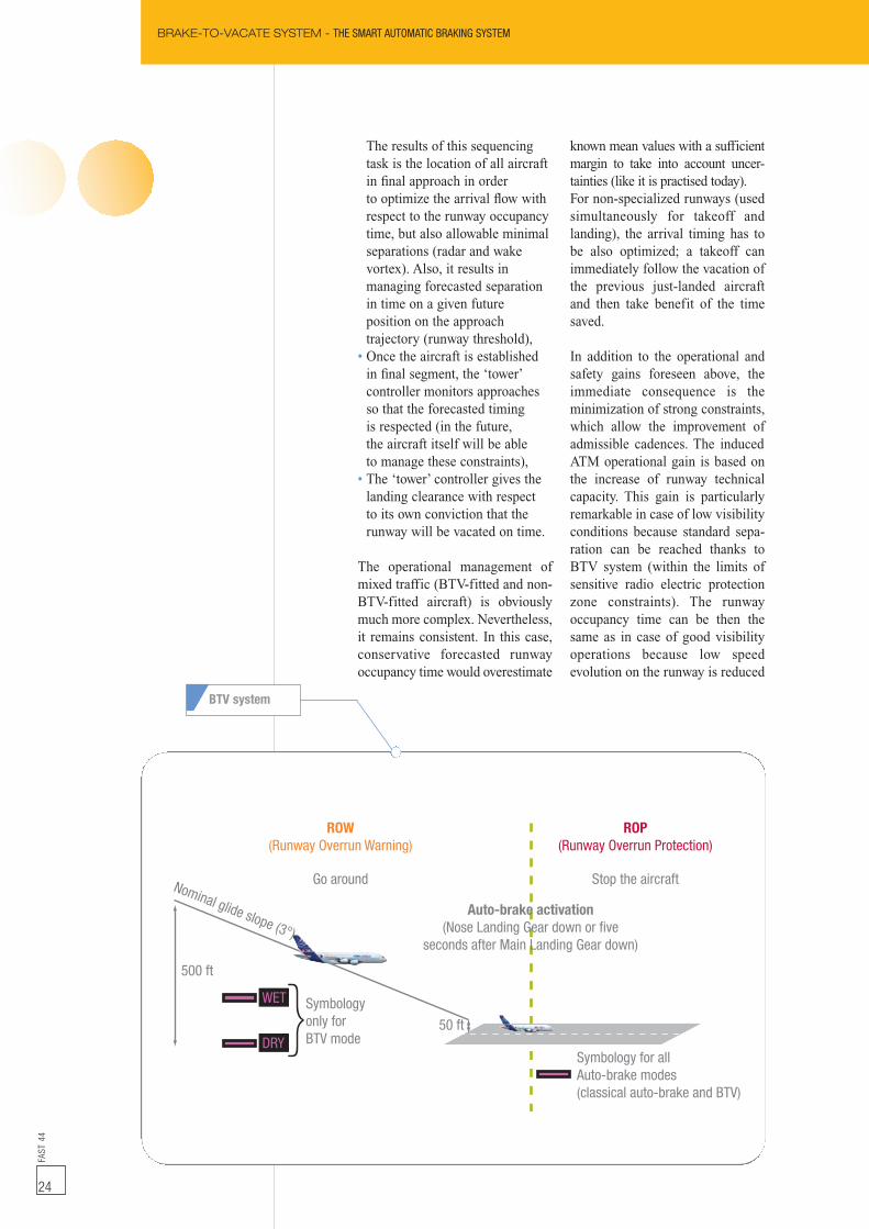
Auto-brake activation(Nose Landing Gear down or five
seconds after Main Landing Gear down)
Symbology for allAuto-brake modes(classical auto-brake and BTV)
Symbologyonly forBTV mode
WET
DRY
Nominal glide slope (3°)
500 ft
50 ft
ROP(Runway Overrun Protection)
Stop the aircraft
ROW(Runway Overrun Warning)
Go around
{
BTV system
25
FAST
44
25
Brake-To-Vacate (BTV) is an Airbusdevelopment effort for improving the pilot’smanagement of the approach and landingphases. The well known GPS and the newon-board airport map databasehas permitted this innovation. Tangiblevalue will be brought to our customers by:• Reducing brake wear and temperature,• Using less and even removingbrake fans,
• Relieving maximum thrust reversers’usage on dry runways,
• Reducing noise level on ground,fuel consumption and gas emission,
• Controlling Turn Around Time beforelanding (guarantee for the nextdeparture slot),
• Improving passengers’ comfortduring landing roll,
• Avoiding missed exit situations,• And, minimizing runwayoccupancy time.BTV system is coupledto a Runway Overrun Prevention system,also called ROW/ROP. This Airbuspatented solution offers a comprehensiveand efficient answer to the runwayexcursion risk at landing.It can then be seen as a major safetyenhancement feature. Through theminimization of the runway occupancytime, BTV helps also to reduce significantlythe exposure time to a runwayincursion risk.
Conclusion
to its minimum. Moreover, asthe runway occupancy time of theprevious aircraft is known andrespected, a certain number of go-around manoeuvres (due to non-cleared runway) will be avoided.
The reduction of the time spent onthe runway can be translated by anoperation time gain for the airline.It could be negligible for anisolated aircraft but important for afleet. The most visible gains will beobtained on the delays reductionoccurring during airport saturationperiods. Operation gains can thenbe magnified by a network effectwhen considering sets of platformsthat are interconnected with localBTV induced gains. They will bealso sensitive to ‘a hub effect’ dueto an important part of fittedaircraft.
Eventually, the airport managerwill benefit from a declaredimproved operational capacitywithout doing expensive invest-ments (additional and/or exit run-way building, etc.).
CONTACT DETAILS
Fabrice VILLAUMÉMulti-ProgrammeProject LeaderAirbus Systems EngineeringTel: +33 (0)5 61 18 63 50Fax: +33 (0)5 61 18 25 [email protected]
BRAKE-TO-VACATE SYSTEM - THE SMART AUTOMATIC BRAKING SYSTEM
IMPLEMENTING RNP AR - THE OPERATIONAL APPROVALFA
ST44
26
Matthias MAEDERRNP Support Pilot
Flight Operations Support & ServicesAirbus Customer Services
Erwan CADOTAirlines RNP SupportFlight Operations Support & ServicesAirbus Customer Services
ImplementingRNP AR
The operational approval(Required Navigation Performance
Authorization Required)RNP is a navigation technique, which allowsaircraft to fly precisely along a predefinedroute using state-of-the-art on-board navigationsystems and Global Positioning System (GPS).RNP improves the efficiency, capacity andenvironmental performance of the global airtransportation system. RNP AR will support thedevelopment of even more efficient procedures interms of fuel emissions, aircraft noise, weather-related minima, access to mountainous areas andairport congestion (see figure 1). RNPAR is one ofthe possible solutions for future ATM (Air TrafficManagement) requirements and optimized flightoperations, being part of the Performance Based
Navigation (PBN) for which the ICAO(International Civil Aviation Organization) hasannounced that it must be implemented all aroundthe world. Very soon, operators will have tochallenge their future flight operations. Operatorsmay have already noticed the publication of newRNP, RNP AR or RNP SAAAR (Specific AircraftAircrewAuthorization Required) approaches at someairports. RNP AR operations cover approaches,missed approaches, SID (Standard InstrumentDeparture) and EOSID (Engine-out SID)procedures. This article describes the variousaspects an operator has to cover when seeking foran operational approval for RNP AR operations.
FAST
44
27
IMPLEMENTING RNP AR - THE OPERATIONAL APPROVAL
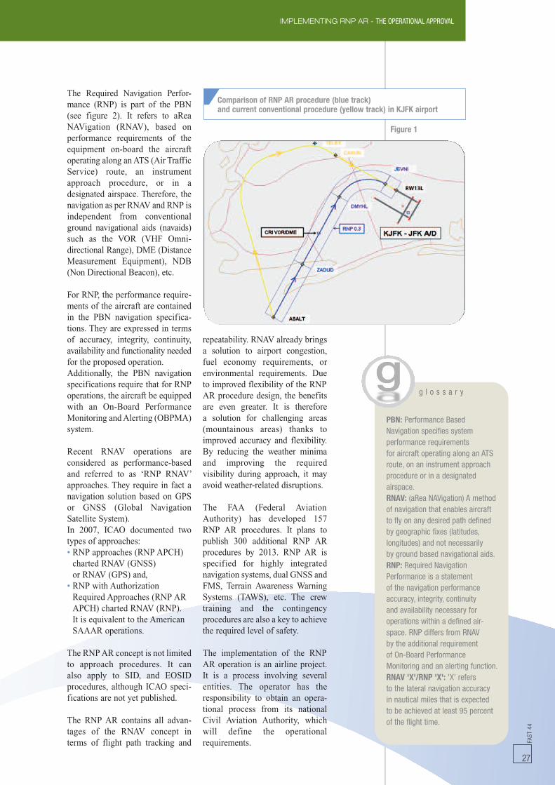
Comparison of RNP AR procedure (blue track)and current conventional procedure (yellow track) in KJFK airport
Figure 1
The Required Navigation Perfor-mance (RNP) is part of the PBN(see figure 2). It refers to aReaNAVigation (RNAV), based onperformance requirements of theequipment on-board the aircraftoperating along anATS (Air TrafficService) route, an instrumentapproach procedure, or in adesignated airspace. Therefore, thenavigation as per RNAV and RNP isindependent from conventionalground navigational aids (navaids)such as the VOR (VHF Omni-directional Range), DME (DistanceMeasurement Equipment), NDB(Non Directional Beacon), etc.
For RNP, the performance require-ments of the aircraft are containedin the PBN navigation specifica-tions. They are expressed in termsof accuracy, integrity, continuity,availability and functionality neededfor the proposed operation.Additionally, the PBN navigationspecifications require that for RNPoperations, the aircraft be equippedwith an On-Board PerformanceMonitoring andAlerting (OBPMA)system.
Recent RNAV operations areconsidered as performance-basedand referred to as ‘RNP RNAV’approaches. They require in fact anavigation solution based on GPSor GNSS (Global NavigationSatellite System).In 2007, ICAO documented twotypes of approaches:• RNP approaches (RNP APCH)charted RNAV (GNSS)or RNAV (GPS) and,
• RNP with AuthorizationRequired Approaches (RNP ARAPCH) charted RNAV (RNP).It is equivalent to the AmericanSAAAR operations.
The RNPAR concept is not limitedto approach procedures. It canalso apply to SID, and EOSIDprocedures, although ICAO speci-fications are not yet published.
The RNP AR contains all advan-tages of the RNAV concept interms of flight path tracking and
repeatability. RNAV already bringsa solution to airport congestion,fuel economy requirements, orenvironmental requirements. Dueto improved flexibility of the RNPAR procedure design, the benefitsare even greater. It is thereforea solution for challenging areas(mountainous areas) thanks toimproved accuracy and flexibility.By reducing the weather minimaand improving the requiredvisibility during approach, it mayavoid weather-related disruptions.
The FAA (Federal AviationAuthority) has developed 157RNP AR procedures. It plans topublish 300 additional RNP ARprocedures by 2013. RNP AR isspecified for highly integratednavigation systems, dual GNSS andFMS, Terrain Awareness WarningSystems (TAWS), etc. The crewtraining and the contingencyprocedures are also a key to achievethe required level of safety.
The implementation of the RNPAR operation is an airline project.It is a process involving severalentities. The operator has theresponsibility to obtain an opera-tional process from its nationalCivil Aviation Authority, whichwill define the operationalrequirements.
g l o s s a r y
PBN: Performance BasedNavigation specifies systemperformance requirementsfor aircraft operating along an ATSroute, on an instrument approachprocedure or in a designatedairspace.RNAV: (aRea NAVigation) A methodof navigation that enables aircraftto fly on any desired path definedby geographic fixes (latitudes,longitudes) and not necessarilyby ground based navigational aids.RNP: Required NavigationPerformance is a statementof the navigation performanceaccuracy, integrity, continuityand availability necessary foroperations within a defined air-space. RNP differs from RNAVby the additional requirementof On-Board PerformanceMonitoring and an alerting function.RNAV 'X'/RNP 'X': 'X' refersto the lateral navigation accuracyin nautical miles that is expectedto be achieved at least 95 percentof the flight time.
IMPLEMENTING RNP AR - THE OPERATIONAL APPROVALFA
ST44
28
For the operational approval, theairline will have to address typicallythe following topics:• Operational evaluationof each RNP AR procedure,
• Validation of the navigationdatabase,
• Flight Operation SafetyAssessment (FOSA),
• Operational documentation,• Procedure charts, specific flightcrew procedures, limitations,
• Aircraft capability,• Flight crew training,• RNP monitoring programme.
Airbus is supporting airlines as anaircraft manufacturer. It includesthe aircraft definition, the opera-tional documentation update andthe RNP monitoring programme. Aservice provider may be involved,for the design of a new RNP ARprocedure, with procedure charts,navigation database coding orprocedure evaluation. The serviceoffer may also include a FOSA asrequired, flight crew proceduresand flight crew training.
The designof proceduresRNP AR operations are based onRNP AR procedures. RNP ARprocedures are designed based onspecific criteria like SAAARprocedures design criteria (FAAOrder 8260.52) or ICAO Manualfor Implementation of the RequiredNavigation Performance. ‘Public’procedures are already availableto all operators; an operator candevelop ‘private’ or ‘tailored’SAAAR instrument procedureswith more flexible criteria.RNP AR approach procedures arecharacterized by:• RNP values ≤ 0.3NM (down to0.1NM) and/or,
• Curved flight path before andafter the FinalApproach Fix (FAF),
• Protection areas laterally limitedto 2xRNP value without anyadditional buffer.
RNP AR missed approach andinstrument departures proceduresinclude a reduced RNP (<1NM).
RNPAR procedures are predictableand repeatable trajectories based onsequenced of fixed legs composedof Track to a Fix leg (TF) andRadius to a Fix leg (RF) in WGS84 coordinates. Sequences ofTF andRF legs offer flexibility in flight pathgeometry that allows designingmore efficient routes, thanks toRNP AR procedures.The specific authorization require-ment is indicated on the RNP ARprocedure charts. RNP AR approa-ches are charted as ‘RNAV (RNP)RWY XX’.
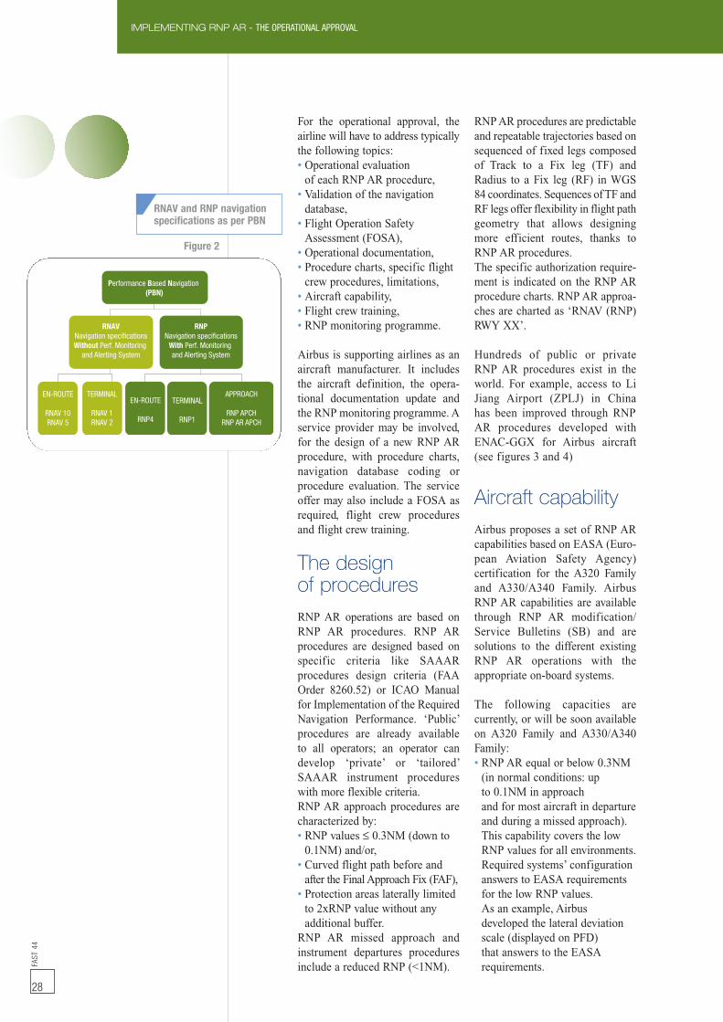
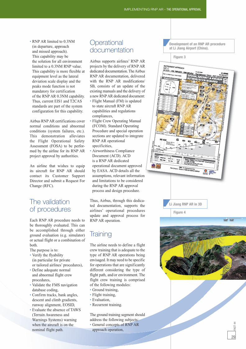
Hundreds of public or privateRNP AR procedures exist in theworld. For example, access to LiJiang Airport (ZPLJ) in Chinahas been improved through RNPAR procedures developed withENAC-GGX for Airbus aircraft(see figures 3 and 4)
Aircraft capabilityAirbus proposes a set of RNP ARcapabilities based on EASA (Euro-pean Aviation Safety Agency)certification for the A320 Familyand A330/A340 Family. AirbusRNP AR capabilities are availablethrough RNP AR modification/Service Bulletins (SB) and aresolutions to the different existingRNP AR operations with theappropriate on-board systems.
The following capacities arecurrently, or will be soon availableon A320 Family and A330/A340Family:• RNP AR equal or below 0.3NM(in normal conditions: upto 0.1NM in approachand for most aircraft in departureand during a missed approach).This capability covers the lowRNP values for all environments.Required systems’ configurationanswers to EASA requirementsfor the low RNP values.As an example, Airbusdeveloped the lateral deviationscale (displayed on PFD)that answers to the EASArequirements.
RNAVNavigation specificationsWithout Perf. Monitoring
and Alerting System
EN-ROUTE
RNAV 10RNAV 5
TERMINAL
RNAV 1RNAV 2
EN-ROUTE
RNP4
TERMINAL
RNP1
APPROACH
RNP APCHRNP AR APCH
RNPNavigation specifications
With Perf. Monitoringand Alerting System
Performance Based Navigation(PBN)
RNAV and RNP navigationspecifications as per PBN
Figure 2
FAST
44
29
IMPLEMENTING RNP AR - THE OPERATIONAL APPROVAL
• RNP AR limited to 0.3NM(in departure, approachand missed approach).This capability may bethe solution for all environmentlimited to a 0.3NM RNP value.This capability is more flexible atequipment level as the lateraldeviation scale display and thepeaks mode function is notmandatory for certificationof the RNP AR 0.3NM capability.Thus, current EIS1 and T2CASstandards are part of the systemconfiguration for this capability.
Airbus RNPAR certifications covernormal conditions and abnormalconditions (system failures, etc.).This demonstration alleviatesthe Flight Operational SafetyAssessment (FOSA) to be perfor-med by the airline for its RNP ARproject approval by authorities.
An airline that wishes to equipits aircraft for RNP AR shouldcontact its Customer SupportDirector and submit a Request ForChange (RFC).
The validationof proceduresEach RNP AR procedure needs tobe thoroughly evaluated. This canbe accomplished through eitherground evaluation (e.g. simulator)or actual flight or a combination ofboth.The purpose is to:• Verify the flyability(in particular for privateor tailored airlines’ procedures),
• Define adequate normaland abnormal flight crewprocedures,
• Validate the FMS navigationdatabase coding,
• Confirm tracks, bank angles,descent and climb gradients,runway alignment, EOSID,
• Evaluate the absence of TAWS(Terrain Awareness andWarnings Systems) warningwhen the aircraft is on thenominal flight path.
Operationaldocumentation
Airbus supports airlines’ RNP ARprojects by the delivery of RNPARdedicated documentation.TheAirbusRNP AR documentation, deliveredwith the RNP AR modifications/SB, consists of an update of theexisting manuals and the delivery ofa new RNPAR dedicated document:• Flight Manual (FM) is updatedto state aircraft RNP ARcapabilities and regulationscompliances,
• Flight Crew Operating Manual(FCOM). Standard OperatingProcedure and special operationsections are updated to integrateRNP AR operationalspecificities,
• Airworthiness ComplianceDocument (ACD). ACDis a RNP AR dedicatedoperational document approvedby EASA. ACD details all theassumptions, relevant informationand limitations to be consideredduring the RNP AR approvalprocess and design procedure.
Thus, Airbus, through this dedica-ted documentation, supports theairlines’ operational proceduresupdate and approval process forRNP AR operation.
TrainingThe airline needs to define a flightcrew training that is adequate to thetype of RNP AR operations beingenvisaged. It may need to be specificfor operations that are significantlydifferent considering the type offlight path, and/or environment. Theflight crew training is comprisedof the following modules:• Ground training,• Flight training,• Evaluation,• Recurrent training.
The ground training segment shouldaddress the following subjects:• General concepts of RNP ARapproach operation,
Development of an RNP AR procedureat Li Jiang Airport (China).
Li Jiang RNP AR in 3D
1150011500
1150
011
500
1050
010
500
9500
9500
9500
9500
95009500
95009500
9500
9500
95009500
95009500
95009500
95009500
9500
950095
0095
0095
0095
00
95009500
7500
7500
75007500
75007500
75007500
75007500
75007500
75007500
7500
7500
75007500
75007500
75007500
183°
183°
311°311°
198°
198°
198°
198°
198°
198°
RF RF
223°
223°
RFRF
RFRF RFRF
RFRF
7.9
7.9
5.15.1
13.813.8
2.52.5
12.112.1
20.1
20.1
7.67.6
3.13.1
3.63.6
5.15.1
2.22.2
10 NM
W
10 NM
W LJ412
LJ413
LJ414
LJ415
2.9°
12500LJ406
Max IAS180 kt
15700LJ401
IAFIAF
Max IAS210 Kt
Max IAS210 kt
13000LJ405
11540
IFIFLJ407
10420LJ408
9740LJ409
9000
PFAFPFAFLJ410
LJ411
RW2026°40'
26°30'
26°20'
26°50'
27°00'
100° 10' 100° 20'
100° 00'
100° 30'
W 381
15700LJ401
309°309°
129°129°
311°311°
Max IAS : 230 kt
Max Protection Altitude : 19000’/ 5800 m
GNSS holding
Missed Approach
1 min 30
1 min 30
1570015700
IAFIAF
ALT MNM 25 NMW
360°
100°
190°
15000
20400
16000
Minimum Sector Altitude
20400 ft15700 ft
12500 ft11540 ft10420 ft
6220 m4790 m14000 ft 4270 m13000 ft 3970 m
3810 m3520 m3180 m9740 ft 2970 m9000 ft 2750 m
Conversion table (QNH)
CAT. CINSTRUMENT APPROACH
AD ELEV. : 7358, THR ELEV. : 7358 (263 hPa) LI JIANGAD2 ZPLJ IAC-4
19 JAN 2009Final Approach / RNAV - RNP SAAAR RWY20
SPECIAL AIRCRAFT & AIRCREWAUTHORIZATION REQUIRED
SPECIAL AIRCRAFT & AIRCREWAUTHORIZATION REQUIRED 1° W(08)
VAR
TWR : LI JIANG Tower 118.45 (130.00)
Aircraft wingspan equal to orless than 136 ft only
For uncompensated Baro VNAV :Minimum Temperature -11°C
SAAAR RequirementsSAAAR Requirements
RF Capacity Required
Missed Approachfrom LJ413 to LJ401
Missed Approachfrom RW20 to LJ413
From LJ406 to RW02
From LJ404 to LJ406
ProcedureLegs
1.0
0.3
0.5
RNPValues
9000
9000
DA
2.52.2
3.63.1
5.1
Next WPt (NM)RW02 (NM)
THR: 7358 TCH : 45
9500 9500
1110012300
974010420
11540 12500
2.9°
RW20LJ411
2.9°
198°198°
7.6 9.8 13.416.5
21.6
5.10.01.3
LJ409 LJ408 LJ407LJ406
LJ405
PFAF
IFLJ410
198°
223°
RFRF
RF
Procedure GP (2.9°)and PAPI (3,5°)are not coincidental
3600
7990 / 24403200
ALS out
with ALS
RNP 0.3 DA (ft / m)Vis (m)
C
CategoryAerodrome MINIMA
640 / 200
DH (ft / m) Climb to 15700 ft, via the RNAV RNP missed approachto LJ401 and hold.Do not exceed 210 kts until LJ415.Keep RNP 0.3 until LJ413.
Missed Approach
86598659
81968196
77247724
82948294
87778777
90759075
Géo
TITA
N®
&A
IP-G
ISC
har
tin
g®
Pro
ced
ure
des
ign
and
char
tin
g: b
yEN
AC
/CG
x-A
ERO
inSY
S-Pr
oc
for A
IRBU
S-
©20
08
FAA Criteria - Orders n°8260.3B-8260.52-8260.54
Mis
sed
Ap
pro
ach
GN
SSH
old
ing
:IC
AO
Cri
teri
a- D
oc
8168
-OPS
/611
Fro
mFe
eder
sto
MA
HP
:FA
AC
rite
ria
CHG : For Operational Use.
TA
>1031 hPa17716’/ 5400 m
< 979 hPa
16732’/ 5100 m15748’/ 4800 m
QNH
TL : 18701’/ 5700 m
AD ELEV. : 735
INSTRUMENCAT. C
TWR : LI JIANG Tow
, THR ELEV. : 7358 (2658,
NT APPROACH
SA
wer 118.45 (130.00)ppFinal Approac
19 JAN 200963 hPa)SPECIIAL AIRCRAUTHHORIZAATIIOT
RNAV - RNP SAAA/chh AD
RARAFFT & AIRCREON REQUIRED
RWY20ARIAC-4ZPLJD2
LI JIANG
W VAR
(08)1° WA
Minimum Sect
c81
68-O
PS/6
11o
ia- D
er
1100
tor AltitudeA
AAAAAAAAAAAAAAAA
TL
54
0000 00'1
000° 01001
115
00000000000000 IILJ407
1LJ40
LJ4
AUTHORIIZATTIOZAAee
00ss 0000
RRAA RR nniiRR uuqqReqReqRR iiA iA irr eeAR eAR e ttttss
18701’/ 5700 mL :
55 00
kt 2 FF1
505099
00555005005050
50500099
0055900
900
5050
750
75000500
500
070 3
22
RFRF55
232333
500
332323
FFRFRFRRRR0 RRFFRRFF1155 11
13
0S LJ406
100 2100 2ax A
LJ4
7
08
409
2.9°
7575
55
33
0075
075
0
1 0 20
ON REQUIRED
77757070755
9595
MM
0°
77
MM
55000095950000959500005050
7575505050500000505000000075755050750075005050500500RRRR
MMaa
FFRRRR
AA
FF100 30
222xxMMMM xx IIxx SS
KSSASAS
00x Sx S
1112100221210002
1 0
405
(08)
2008
©U
S-
or A
IRB
cffo
orP
Conversion ta
itrO
CA
ICo
ldin
g::
chG
NSS
H
75755550500000000075075075007500500500
able (QNH)
7575
9595
9595
1010
PP
AA
15
050550500000
05050000
050
050
1000
10005050
9595
50500000
990000
950
950
900
900500
500 55
5050000000
950
950
9500
95005050 00
505000009595000095095095009500500500
750
75000000000
7500
7500500
500
LJ401FFAFAF
0LJ410
7575
99
75759595
959599
550099
000055559 00
90000
88
505000000000
950
950
9500
95000000
50500000
9900
95959500
9500500
500
75075000000075007500500500
99 55000000007575750075005050
242411989888989899
191988
9919191111889988
LJ411
RW20
111199
88 9696
59598 58 5
19198 98 9
77
6699
77 4444
55
77
5050009595 0000000000
5500007
007
005050
S-P
Oin
SYG
x-A
ERC
/Cy
ENA
bg
::
MissedGNSS
oac
hp
pr
isse
dA
M
WW 38IAIAFF
ApproachS holdingAAFF
alVRN
00
99
11
11115 115505000000000150 150
1150011500 500 500
999595
MMMM
5050550000
95950000
90
90
950
9500000 500
500
1111
MM0011 NN0 N0 NMM00 NMNMNN
WW
MMMMM
W
M
W
MM
WW
88
luesNP
88 1111
11
881188
8811
88
LJ412
LJ413
LJ415
77
9595
00000055750075000000
tin
ge
des
ign
and
char
edu
rc
orP
x P cPrM onn Ax A 2230 tS :
RWLJ411
0'
F
°
FA
0’/19: 000 / 5800
0
0
1
W20 LJ410
0.5
0.3
1.0
LJ409 LJ408 LJ40
77
15
55
°
55550077557575
54
11
75075000
11 LJ414
2.9°07LJ406
3°
22
LJ405
P
7358(NM)
Next WPt(NM)RW02
7358THR:THR:
198°
RWLJ411
1.3 0ia
eritr
AA
CF
oM
AH
P::
t
ot tc in de a
DA
2
TCH : 459
TCH : 45
e
W20
0.05.1
I )PAra
and 53GP )A
dP
dc°2Gu eeorP
Aerodrome MINIMA
050
RF8
1974097
2.22.5
3.6
422
00
F
13.49.8
7.6
0300
00
5.13.1
16.54
Missed Approach21.6
tin
g®
har
IP-G
ISC
Category
DA (RNP 0.3with ALSALS out
7990
eed
ers
om
FrF
)m/tf(HD
002/046
C
isV(ft / m)
320 / 2440
36
AA CriteriaF
s (m)200600 Keep RNP 0.3 unt
Do not exceed 21holdandLJ401to
15700 ft,toClimb
CHG :ia - Orders n°8260.3B-8260
For Operational U
til LJ413.10 kts until LJ415.
.d V RNP missed apvia the RNAAV
pp
0.52-8260.54
Use.
pproach
AN
®&
AG
éoTI
TTA
Figure 3
Figure 4
IMPLEMENTING RNP AR - THE OPERATIONAL APPROVALFA
ST44
30
The RNP AR definitively benefitsfrom modern navigation equipment.The Performance-Based Navigation (PBN)implementation plan is clear. And somecountries (USA, Australia) have alreadystarted to widely implement the PBNand RNP AR, or RNP SAAAR.Airbus is also convinced of the operationalbenefits of the implementation of the RNPAR operations. The possible advantagesof RNP AR can be found to:• Reduce airport congestion,• Improve fuel consumption,• Reduce gas emissions when associatedto track miles savings,
• Reduce aircraft noise,
• Reduce weather minima inmountainous areas.Airbus has been developing and certifyingRNP AR capability on several aircrafttypes. Airbus believes that RNP is thefuture for Air Traffic Management (ATM)and fully support RNP AR implementationall around the world. Recently, Airbussupported several Chinese authorities andairlines in developing and deploying RNPAR procedures in Yan Ji, Li Jiang, HuangShan and Lhassa airports, to name a few.The time has come for operators all aroundthe world to consider implementing RNPAR as a way of preparing and optimizingthe future of their flight operations.
Conclusion
an AIRBUS subsidiary
CONTACT DETAILS
Capt. Matthias MAEDERRNP Support PilotFlight Operations Support& ServicesAirbus Customer ServicesTel: +33 (0)5 62 11 02 03Fax: +33 (0)5 61 93 29 [email protected]
Erwan CADOTAirlines RNP Support EngineerFlight Operations Support& ServicesAirbus Customer ServicesTel: +33 (0)5 61 93 81 10Fax: +33 (0)5 61 93 29 [email protected]
• ATC (Air Traffic Control)communication and coordinationfor the use of RNP AR,
• RNP AR equipment components,controls, displays and alerts,
• AFM (Aircraft Flight Manual)information and operatingprocedures,
• MEL (Minimum EquipmentList) operating provisions.
The flight training should addressamongst others the followingsubjects:• Normal RNP operationsfor departure, approach,and missed approach,
• Abnormal RNP operationsfor departure, approach,and missed approach,
• Contingency procedures,including existing localprocedures.
The airline needs to evaluate eachflight crew member on their know-ledge of RNP AR procedures. Theairline should include an RNP ARrecurrent training in its overall flightcrew recurrent training programme.
BrochureDetailed information about theRNP AR concept is available forAirbus customers through ‘Gettingto Grips with RNP AR’ (documenton AirbusWorld). This documentpresents the RNP AR concept, aswell as the Airbus solutions andairlines’ activities to conduct theirRNP AR project.
New subsidiaryQuovadisAirbus created a new subsidiary,Quovadis, in cooperation with theFrench Civil Aviation University,ENAC, and CGX AERO in SYS,a specialist in aeronautical andgeographical information systems.Quovadis offers and sells serviceslinked to RNP to airlines, autho-rities and airports. This includesdesign of the RNP procedures,validation and testing of proce-dures, flight operational approvaland flight crew training.
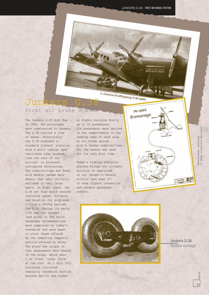
FAST
44
31
JUNKERS G.38 - FIRST AIR BRAKE SYSTEM
Junkers G.38Tandem carriage
The Junkers G.38 first flewin 1929. Two prototypeswere constructed in Germany.The G.38 carried a crewof seven. Structurallythe G.38 confirmed tostandard Junkers' practice,with a multi-tubular sparcantilever wing covered,like the rest of theaircraft in stressed,corrugated duraluminum.The undercarriage was fixed,with double tandem mainwheels that were initiallyenclosed in very largespats. In flight tests, theG.38 set four world recordsincluding speed, distanceand duration for airplaneslifting a 5000kg payload.The G.38, during its earlylife was the largestland plane in the world.Passenger accommodationswere sumptuous by today'sstandards and were meantto rival those offeredby the competing Zeppelinservice offered by Delag.The plane was unique inthat passengers were seatedin the wings, which were1.7m (5feet 7inch) thickat the root. On 1 July 1931Lufthansa initiatedregularly scheduled servicebetween Berlin and London
on flights carrying firstlyup to 13 passengers.Six passengers were carriedin two compartments in theleading edge of each wing.An air brake systemwith a tandem undercarriagefor the wheels was usedfor the very first time.
Today’s braking evolutionsystems brings the ultimatesolution as explainedin our ‘Brake-to-Vacate’article (see page 17)to ease airport congestionand enhance passengercomfort.
Junkers G.38First air brake system
Photographs
courtesy
of
EADS
Corporate
Heritage
Customer Servicesevents
Ju s t h a p p e n e d
A320 Family symposiumThe 11th Airbus A320 Family symposiumwas held in Paris beginning of May. 188representatives from operators, leasing, MRO(Maintenance, Repair and Overhaul) centresand suppliers attended it. During the 3 days ofthe symposium participants reviewed a widerange of subjects in the technical, economicand process domains. The symposium's keytheme was working together to deliversolutions that are both technically andeconomically efficient. This was captured withthe motto, ‘Discuss, Decide, Deliver’. Thesymposium concluded with the caucus sessionthat highlighted key areas for further work.These will compliment the areas of de-velopment that are agreed through the FAIR(Forum for Airline Issues Resolution) process.Feedback during and after the event indicated ahigh level of added value for the majority ofparticipants.
Performance & Flight Operations conference372 people and 111 airlines attended the 16th
Performance and Operations conference inParis from 11 to 15 May 2009. About onehundred presentations were shown, coveringall flight operations activities, such asperformances, Electronic Flight Bag and digi-tal documentation, airline economics, etc ...The operators could also attend sessionsdedicated to different aircraft types, and sharetheir in-service concerns. The caucus,organized on the last day, enabled our operatorsto provide us with their feedback on oursupport in the field of flight operations, butalso on the conference itself.
Com i n g s o o n
Supplier Improvement meetingsOur Supplier Support Management team isorganizing two regional Supplier Improvementmeetings later this year focusing on our
suppliers’ aftermarket improvement initiatives.These meetings will be held in Hamburg on15 and 16 September for European customers,followed by Dubai from the 5 to 7 October forMiddle East customers. The goal is to sharewith our customers, the Airbus developmentsin supplier support management, followingwhich, 10 of our major suppliers will presenttheir improvement plans to the customer groupand hold ‘questions and answers’ sessions.There will also be an opportunity forcustomers to have bilateral meetings withsuppliers. The preliminary list of suppliersparticipating is: DASELL, EADS Sogerma,Eaton, Goodrich Interiors, Goodrich Power,Honeywell, Messier Dowty, Messier Bugatti,Panasonic and Zodiac Services. Invitations forEuropean and Middle East customers will besent in the coming days.
Airbus Leasing Support conference in Dublin,IrelandThe 6th Leasing Support conference will takeplace in Dublin, Ireland on 7 and 8 October2009. This conference is organized for Airbusleasing companies and addresses dedicatedsupport requirements of lessors and airlines,with a specific focus on aircraft residual valueand maintenance events.
A300/A310 Family symposiumThe next A300/A310 Family symposium willbe held in Bangkok, Thailand from 9 to 12November 2009. In order to make this event asproductive as possible for all, Airbus willpropose a basic agenda that will be augmentedwith your suggestions and input from FAIR(Forum for Airline Issues Resolution). Asusual, adequate facilities will be available forside meetings during the event. Airbus Familysymposiums are held for each Airbusprogrammes every two years, and target airlineengineering and maintenance managers. Theprime function of these meetings is to enabletwo-way communication, leading to an eversafer and more efficient fleet.
FAST
44
32

FAST
44
33
Services and Customer Support centresTraining centresMaterial Logistics centres / Regional warehousesResident Customer Support Managers (RCSM)
RCSM location CountryLos Angeles United States of AmericaLouisville United States of AmericaLuton United KingdomLuxembourg LuxembourgMacau S.A.R. ChinaMadrid SpainManchester United KingdomManilla PhilippinesMarrakech MoroccoMauritius MauritiusMelbourne AustraliaMemphis United States of AmericaMexico City MexicoMiami United States of AmericaMilan ItalyMinneapolis United States of AmericaMontreal CanadaMoscow RussiaMumbai IndiaMuscat OmanNanjing ChinaNew York United States of AmericaNoumea New CaledoniaPalma de Mallorca SpainParis FranceParo BhutanPhiladelphia United States of AmericaPhoenix United States of AmericaPrague Czech RepublicRiyadh Saudi ArabiaRoma ItalySan Francisco United States of AmericaSan Salvador El SalvadorSana’a YemenSantiago ChileSao Paulo BrazilSeoul South KoreaShanghai ChinaSharjah United Arab EmiratesShenyang ChinaShenzhen ChinaSingapore SingaporeSofia BulgariaSydney AustraliaTaipei TaiwanTashkent UzbekistanTehran IranTel Aviv IsraelTirana AlbaniaTokyo JapanToluca MexicoToronto CanadaTripoli LibyaTunis TunisiaVienna AustriaWashington United States of AmericaWuhan ChinaXi'an ChinaYekaterinburg RussiaZurich Switzerland
RCSM location CountryAbu Dhabi United Arab EmiratesAlgiers AlgeriaAl-Manamah BahrainAlmaty KazakhstanAmman JordanAmsterdam NetherlandsAthens GreeceAtlanta United States of AmericaAuckland New ZealandBaku AzerbaijanBangkok ThailandBarcelona SpainBeijing ChinaBeirut LebanonBerlin GermanyBogota ColombiaBratislava SlovakiaBucharest RomaniaBudapest HungaryBuenos Aires ArgentinaCairo EgyptCasablanca MoroccoChangchun ChinaCharlotte United States of AmericaChengdu ChinaChicago United States of AmericaCologne GermanyColombo Sri LankaCopenhagen DenmarkDamascus SyriaDelhi IndiaDenver United States of AmericaDhaka BangladeshDoha QatarDubai United Arab EmiratesDublin IrelandDusseldorf GermanyFort Lauderdale United States of AmericaFrankfurt GermanyGuangzhou ChinaGuayaquil EcuadorHaikou ChinaHamburg GermanyHangzhou ChinaHanoi VietnamHelsinki FinlandHong Kong S.A.R. ChinaIndianapolis United States of AmericaIstanbul TurkeyJakarta IndonesiaJeddah Saudi ArabiaJohannesburg South AfricaKarachi PakistanKita-Kyushu JapanKuala Lumpur MalaysiaKuwait City KuwaitLagos NigeriaLanzhou ChinaLarnaca CyprusLisbon PortugalLondon United Kingdom
WORLDWIDEBruce JONESSenior Vice PresidentServices & Customer SupportCustomer ServicesTel: +33 (0)5 61 93 35 04Fax: +33 (0)5 61 93 41 01
USA/CANADATom ANDERSONVice President Services& Customer SupportCustomer ServicesTel: +1 (703) 834 3506Fax: +1 (703) 834 3463
CHINAPierre STEFFENVice President Services& Customer SupportCustomer ServicesTel: +86 10 804 86161 Ext 5040Fax: +86 10 804 86162 / 63
RESIDENT CUSTOMER SUPPORT ADMINISTRATIONJean-Bernard GALY, DirectorResident Customer Support AdministrationTel: +33 (0)5 67 19 04 13Fax: +33 (0)5 61 93 46 10
TECHNICAL, MATERIAL LOGISTICS& TRAINING SUPPORTAirbus has its main Material Logistics centrein Hamburg, and regional warehousesin Frankfurt, Washington D.C., Dubaï, Beijing,Shanghai and Singapore.
Airbus operates 24 hours a day every day.
Airbus Technical AOG Centre (AIRTAC)Tel: +33 (0)5 61 93 34 00Fax: +33 (0)5 61 93 35 [email protected]
Spares AOGs in North America should beaddressed to:Tel: +1 (703) 729 9000Fax: +1 (703) 729 4373
Spares AOGs outside North Americashould be addressed to:Tel: +49 (40) 50 76 4001Fax: +49 (40) 50 76 [email protected]
Spares related HMV issues outsideNorth America should be addressed to:Tel: +49 (40) 50 76 4003Fax: +49 (40) 50 76 [email protected]
Airbus Training Centre Toulouse, FranceTel: +33 (0)5 61 93 33 33Fax: +33 (0)5 61 93 20 94
Airbus Maintenance Training Centre Hamburg,GermanyTel: +49 (40) 74 38 8288Fax: +49 (40) 74 38 8588
Airbus Training subsidiariesMiami, Florida - U.S.A.Tel: +1 (305) 871 36 55Fax:+1 (305) 871 46 49Beijing, ChinaTel: +86 10 80 48 63 40Fax:+86 10 80 48 65 76
CUSTOMER SERVICES WORLDWIDE AROUND THE CLOCK... AROUND THE WORLD