Embed Size (px)
Citation preview
FAN
PO
WER
ED T
ERM
INA
L U
NIT
S
C
C6
FAN POWERED TERMINAL UNITS
Leading The IndustryProviding products that incorporate the desires and requirements of the industry we serve has traditionally been a primary focus at Nailor.We listened in-depth to the engineering and contracting community, asked a lot of questions and realized there was not a single line of fan powered terminals available that incorporated all the design features and performance criteria that satisfied their wishes.After an extensive and intense period of research, design and development, we have produced a line of fan powered terminals that satisfy the vast majority of requirements the HVAC industry demands.On the next page, you can see at a glance some of the unique universal features that have been incorporated into Nailor fan powered terminals, providing the benefits of high performance operation and many field-friendly features to aid installation. All Nailor terminals include the following additional features as standard:• Compatibility with digital, analog electronic and
pneumatic controls.• Fan motors and heaters are energized and dielectric
tests are performed on every terminal to ensure correct operation prior to shipment.
• Custom fabricated motor/blower combinations are mounted on special heavy gauge angles and isolated from casing with rubber insulators.
• All motors incorporate an anti-backward rotation design to prevent backward rotation upon start-up.
• Units can be flipped in the field for right or left hand configuration except Model Series 33SZ.
Model Series 35S. Basic UnitSeries Flow (Constant or Variable Volume)
GENERAL PRODUCT OVERVIEW
Model Series 37SST StealthTM, Hot Water HeatSuper Quiet, Series Flow (Constant or Variable Volume)
Model Series 35NW, Hot Water HeatCompact Design, Parallel Flow (Variable Volume)
Model Series 37NW, Hot Water Heat
Model Series 33SZ. Basic UnitChilled Water, Series Flow, (Constant or Variable Volume)
Model Series 37SE, Electric HeatSeries Flow (Constant or Variable Volume)
Model Series 35SST StealthTM, Hot Water HeatSuper Quiet, Series Flow (Constant or Variable Volume)
FAN
PO
WER
ED TER
MIN
AL U
NITS
C
C7
FAN POWERED TERMINAL UNITS
Introduction
Fan Powered Terminal Units are an economical means of both cooling and periodically heating the perimeter zones of a building utilizing a single duct control system. In addition to inherent VAV economies, fan terminals utilize the free heat derived from lighting, people and other equipment and induce this warmer plenum air from the building core ceiling plenum space and re-circulate it to rooms calling for heating. If additional heating is required, optional supplementary heating coils may be activated. The need for a central source of warm air is eliminated.
During weekend or night-time operation, the central fans may be turned off. Heat, if required, may be provided by the terminal unit fan itself.
Fan Powered Terminal Units are the most popular design for office buildings because they provide performance benefits by reducing first cost, (such as lower central system fan HP and smaller ductwork), lower operating cost, the recovery of waste heat, and the capacity for improved air circulation and diffuser performance.
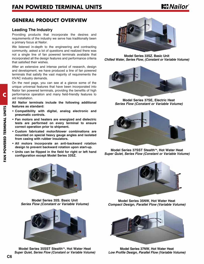
Fan terminals are available in two basic configurations; series or parallel flow. Each contains a fan motor assembly and a variable air volume damper to modulate primary air.
In a series unit (Fig. 1), the fan sits in the primary air stream and runs constantly when the zone is occupied. In a parallel unit (Fig. 2), the fan sits outside the primary air stream and runs intermittently.
Although both terminals can provide central fan HP savings, each terminal has different inlet static pressure requirements. Series fan terminals boost both induced air and primary air, so the inlet static pressure only needs to overcome the loss across the damper [less than 0.05" w.g. (12 Pa)] with Nailor terminals. Parallel fan terminals require enough static pressure to overcome the losses across the damper, the downstream ductwork and diffusers [typically 0.25 — 0.5" w.g. (62 — 124 Pa)] with Nailor terminals.
Series Flow Terminals – (Constant Volume)A series fan powered terminal unit mixes primary air with induced plenum air by using a continuously operating fan during the occupied mode. It provides a constant volume of air to the space regardless of load.
As the cooling load decreases, the zone thermostat throttles the primary air valve. The terminal fan makes up the difference by inducing more return air from the plenum. At low cooling loads, the primary air may close or go to a minimum ventilation setting. If the zone temperature drops still further, the thermostat can energize optional supplemental heat. The sequence reverses when the load is increased.
The series terminal is therefore a constant volume, variable temperature unit. (See Fig. 3).
Series units should only be used with pressure independent controls. Series fans must be adjusted to match the maximum cooling cfm, to ensure that the primary air does not exceed
Design Characteristics and Application
ELECTRICALCONTROLS
ENCLOSURE
DISCHARGEAIR OPTIONAL
ELECTRIC HEAT
FAN/MOTOR
INDUCEDPLENUM
AIR
PRIMARYAIR
PRIMARYAIR VALVE
Figure 1. Series Fan Terminal
the fan cfm as this would result in the short-circuiting of primary air directly into the ceiling plenum and waste energy. A pressure independent controller and inlet flow sensor controls the primary air valve to compensate for changes in inlet static pressure and ensures design cfm is maintained.
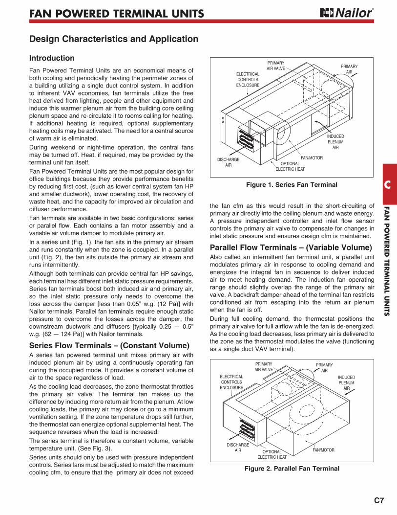
Parallel Flow Terminals – (Variable Volume)Also called an intermittent fan terminal unit, a parallel unit modulates primary air in response to cooling demand and energizes the integral fan in sequence to deliver induced air to meet heating demand. The induction fan operating range should slightly overlap the range of the primary air valve. A backdraft damper ahead of the terminal fan restricts conditioned air from escaping into the return air plenum when the fan is off.
During full cooling demand, the thermostat positions the primary air valve for full airflow while the fan is de-energized. As the cooling load decreases, less primary air is delivered to the zone as the thermostat modulates the valve (functioning as a single duct VAV terminal).
ELECTRICALCONTROLS
ENCLOSURE
PRIMARYAIR VALVE
PRIMARYAIR
DISCHARGEAIR OPTIONAL
ELECTRIC HEAT
FAN/MOTOR
INDUCEDPLENUM
AIR
Figure 2. Parallel Fan Terminal
FAN
PO
WER
ED T
ERM
INA
L U
NIT
S
C
C10
FAN POWERED TERMINAL UNITS
The Diamond Flow multi-point averaging sensor is standard on all Nailor terminal units that are equipped with pressure independent controls.In addition to the Diamond Flow multi-point averaging sensor and opposed blade damper configuration of the primary air valve that are described in detail on page O11 in this catalog, all Nailor fan powered terminals incorporate the following features and benefits.
Single Speed PSC Induction MotorsAll Nailor fan powered terminal units are currently equipped with single speed, direct drive, fractional horsepower, high efficiency, PSC motors as standard. These motors are manufactured to specifications developed by Nailor specifically for the fan powered terminal unit market. Some of the more important features of PSC motors are listed and explained below.• No Corona Effect
Motors not only provide power, but act as transformers and generators. Under certain conditions, this causes the unused speed taps in multiple speed motors to have large potential or static charges present. While these charges are not doing any work, they will create damage to the windings if their potential voltages are greater than the winding insulating quality. This is often the case and lifetimes are shortened. Nailor fan powered terminal units do not suffer from this malady. All motors are single speed.
• Wide Operating Ranges
Nailor motors are designed to operate at rotational speeds lower than those of our competitors. This requires special stator wire sizing, special capacitor sizing and special bearings. These items are covered in our specifications. This assures you of high end performance equal to or better than any of our competitors and low end ranges below any of our competitors.
Low end performance is often ignored. Many times, this is because the range is not great enough to allow much difference, or because the low end performance is achieved by artificial means such as manual dampers to lower the airflows. Manual dampers lower airflows, but they increase RPM. Increased RPM puts back all the noise generated in the fan powered terminal unit as if it were still operating at full airflow. This is due to the noise caused by tip speed and vibration within the unit. High RPM, regardless of airflow will generate high noise.
Nailor solves this problem through low RPM for low airflows. Typically, the motors in Nailor fan powered terminal units can rotate as low as 350 RPM at low end, shedding as many as 14 to 20 decibels in the second and third octave bands depending on which unit is being selected. This means real sound level selections, units that can produce NC's of 30 and 35 when applied correctly and wider operating ranges on individual units for greater flexibility in the zone.
Common Fan Terminal Components
• Permanently Lubricated Motors Nailor fan powered terminal units are equipped with
permanently lubricated motors. The motors are equipped with oilers, but the oilers are not necessary as long as the units are operated in typical ambient temperature conditions. The specifications call for the oil reservoirs to have at least 50% of the original oil still in the reservoir after 50,000 hours of use under normal conditions.
• Permanent Split Capacitor Design All Nailor fan powered terminal units are supplied with
PSC motors as standard. The capacitors are sized to provide ample starting torque, even when turned down to the low minimums allowed on Nailor fan powered terminal units.
• High Efficiency All Nailor PSC motors have the highest efficiency available
in the market today. This too, is controlled by the Nailor motor specifications. Higher efficiency means lower operating expenses.
PSC Fan Speed ControllersNailor designed its own solid state fan speed controllers. They are designed to operate with the specific motor and blower combinations as used in Nailor fan powered terminal units. They provide smooth and infinite adjustment of motor speed from maximum to the lowest preset low end limits found in the industry.The speed controllers are largely responsible for the operating ranges of the motors. High quality standards allow very accurate low end stops. This assures Nailor customers of sound levels and performance as cataloged.The matching of the motors and speed controllers allows Nailor fan powered terminal units lower watt consumption as motor RPM's are reduced. High efficiency is maintained from high end performance to low end performance. Very few of our competitors can make a similar claim.
Low Noise Levels – AHRI CertifiedIn addition to those items listed above, Nailor holds down noise levels in the occupied space with heavy gauge metal casings, dual density insulation and multiple isolation points between motors and casings. Nailor is as quiet as any and far quieter than most of our competitors when controlling similar airflows on competitive equipment. Check out the sound data in this catalog. Notice there is no fine print covering the conditions under which the data does not apply. Notice that the minimum static requirement on series fan powered terminal units is 0.05" w.g. (12 Pa). Then notice the correspondingly low inlet static pressures on the parallel units. Notice that Nailor sound data is AHRI certified and independently certified by Energistics Laboratory, Houston. Compare that to the competition.
FAN
PO
WER
ED TER
MIN
AL U
NITS
C
C11
FAN POWERED TERMINAL UNITS
ECM/EPIC FAN TECHNOLOGY®
compared to PSC motors)• Unique factory pre-set air volume capability• Pressure independent fan operation• LED for visual indication of air volume• Field adjustable fan air volume controller• Remote fan air volume adjustment capability from BAS
tenant changes
Since 1985, equipment manufacturers have used ECM's in residential air conditioners and furnaces. These motors have made it possible to achieve SEER ratings of 12 and higher. Nailor first introduced the ECM to the commercial HVAC market (ASHRAE Journal, April 1997) as an option for use in series fan powered terminal unit applications.
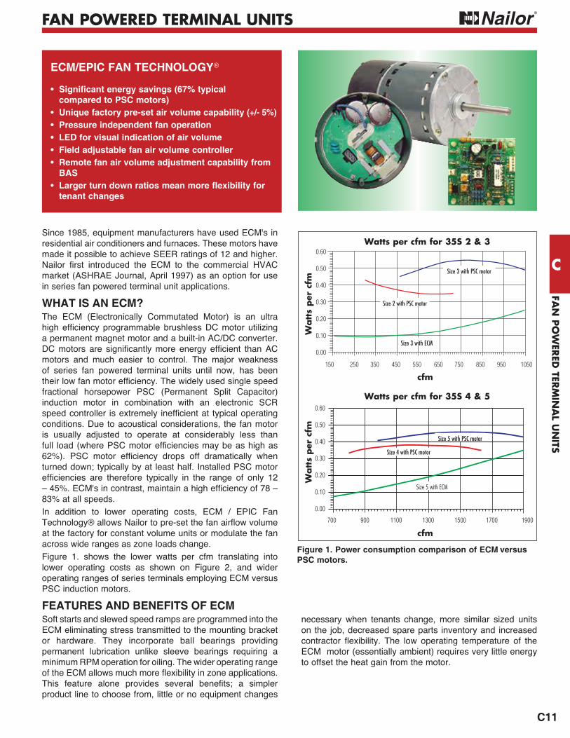
WHAT IS AN ECM?The ECM (Electronically Commutated Motor) is an ultra high efficiency programmable brushless DC motor utilizing a permanent magnet motor and a built-in AC/DC converter. DC motors are significantly more energy efficient than AC motors and much easier to control. The major weakness of series fan powered terminal units until now, has been their low fan motor efficiency. The widely used single speed fractional horsepower PSC (Permanent Split Capacitor) induction motor in combination with an electronic SCR speed controller is extremely inefficient at typical operating conditions. Due to acoustical considerations, the fan motor is usually adjusted to operate at considerably less than full load (where PSC motor efficiencies may be as high as 62%). PSC motor efficiency drops off dramatically when turned down; typically by at least half. Installed PSC motor efficiencies are therefore typically in the range of only 12 – 45%. ECM's in contrast, maintain a high efficiency of 78 – 83% at all speeds.In addition to lower operating costs, ECM / EPIC Fan Technology® allows Nailor to pre-set the fan airflow volume at the factory for constant volume units or modulate the fan across wide ranges as zone loads change.Figure 1. shows the lower watts per cfm translating into lower operating costs as shown on Figure 2, and wider operating ranges of series terminals employing ECM versus PSC induction motors.
FEATURES AND BENEFITS OF ECMSoft starts and slewed speed ramps are programmed into the ECM eliminating stress transmitted to the mounting bracket or hardware. They incorporate ball bearings providing permanent lubrication unlike sleeve bearings requiring a minimum RPM operation for oiling. The wider operating range of the ECM allows much more flexibility in zone applications. This feature alone provides several benefits; a simpler product line to choose from, little or no equipment changes
Watt
s per
cfm
Watt
s per
cfm
0.60
0.50
0.40
0.30
0.20
0.10
0.00
0.60
0.50
0.40
0.30
0.20
0.10
0.00
Watts per cfm for 35S 2 & 3
cfm
Watts per cfm for 35S 4 & 5
150 250 350 450 550 650 750 850 950 1050
cfm700 900 1100 1300 1500 1700 1900
Size 3 with PSC motor
Size 2 with PSC motor
Size 3 with ECM
Size 5 with PSC motor
Size 4 with PSC motor
Size 5 with ECM
Figure 1. Power consumption comparison of ECM versus PSC motors.
necessary when tenants change, more similar sized units on the job, decreased spare parts inventory and increased contractor flexibility. The low operating temperature of the ECM motor (essentially ambient) requires very little energy to offset the heat gain from the motor.

FAN
PO
WER
ED T
ERM
INA
L U
NIT
S
C
C12
FAN POWERED TERMINAL UNITS
Figure 2. Typical operating cost comparison.
ECM/EPIC FAN TECHNOLOGY®
These features also extend the life of the ECM, which are expected to provide an average 90,000 hours of operation. This translates into about 25 years for a typical series fan powered terminal unit. In addition to these standard features are two primary benefits; energy savings and the ability to pre-set the fan airflow volume at the factory.
HOW DO YOU PRE-SET FAN AIRFLOW?Pre-setting the fan airflow (cfm) has always been a problem for fan powered terminal manufacturers for two major reasons. First is that AC motors are not synchronous machines and second the RPM and consequently the unit cfm, changes when static pressure changes. The difficulty in pre-setting the fan lies in estimating the motor workload required at the job site in actual working conditions. The fan will not produce the same volume of air as it did at the factory without the duct work. Because there is no way to accurately predict the downstream static pressure as it would exist at the job site, it was impossible to pre-set the fan cfm. The ECM's are DC and inherently synchronous machines. The motors are programmed to calculate the work they are doing and then compare the work accomplished to the cfm requirement. The integral microprocessor based controller automatically adjusts the speed and torque in response to system pressure changes and pressure independent constant airflow operation is achieved without the need for an external flow sensor feedback loop. Nailor series fan powered terminal units incorporate our own custom EPIC fan controller. An electronic PWM volume control device that allows adjustment of airflow volume. This value can be pre-set on the assembly line. It is field adjustable either manually using a screwdriver and voltmeter locally at the terminal or more conveniently, remotely using a 0 – 10 VDC analog output from a digital controller via the BAS. A fan volume versus DC volts calibration chart is provided. The importance of this feature is that the balancer never has to go into the ceiling to adjust the fan. This relieves the balancer of most of his work per zone on fan powered terminal units and related headaches. This also removes the uncertainty of diffuser flow measurement with hoods. Laboratory tests show the fan cfm to be accurate within +/- 5% of the factory set point. This is a huge benefit to the owner, the controls contractor, the mechanical contractor and the ceiling contractor.
ENERGY SAVINGSThe following graphs show the energy savings of units with ECM's compared to units with Nailor engineered PSC motors Since PSC motors used by Nailor are built specifically for Nailor fan powered terminal units and are more efficient than those used by most of our competitors.A comparison using Nailor units with ECM's and a competitor's units with PSC motors would show even greater savings.The typical range of operation for the size 3 would be 200 to about 900 cfm (94 to 425 l/s). The typical range of operation for the size 5 unit would be 700 to 1700 cfm (330 to 802 l/s).
WHAT IS THE PAYBACK PERIOD ON ECM MOTORS?The payback period varies. It depends on which unit you use, where you set the cfm, how much you run the equipment and what you are paying for electricity. The graphs above are calculated assuming 66 hours per week operations and $ .10 per kWh. If you run the equipment longer in your building or if you pay more for electricity, the payback will change proportionally. Considering the pre-set capability of the motor, there should be an up-front savings on balancing. That should be rebated to the owner and should be considered as part of the payback from the motor. Typically, with the balancing rebate and the operating expenses as shown above, the payback period should be anywhere from 6 to 18 months.
cfm
Ann
ual D
olla
rs
$200
$150
$100
$50
$0200 400 600 800 1000
Size 4 & 5 PSC vs. Size 5 ECM Motors
Ann
ual D
olla
rs
$300
$250
$200
$150
$100
$50
$0700 1000 1300 1600 1900
PSC Motor ECM
Size 2 & 3 PSC vs. Size 3 ECM Motors
cfm
FAN
PO
WER
ED TER
MIN
AL U
NITS
C
C13
FAN POWERED TERMINAL UNITS
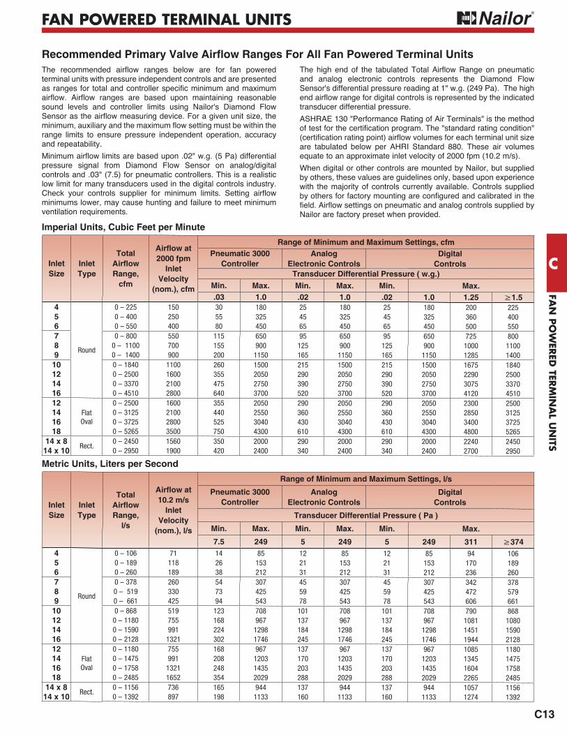
Recommended Primary Valve Airflow Ranges For All Fan Powered Terminal Units
Imperial Units, Cubic Feet per Minute
Metric Units, Liters per Second
Inlet Size
InletType
Total Airflow Range,
cfm
Airflow at 2000 fpm
InletVelocity
(nom.), cfm
Range of Minimum and Maximum Settings, cfmPneumatic 3000
ControllerAnalog
Electronic ControlsDigital
ControlsTransducer Differential Pressure ( w.g.)
Min. Max. Min. Max. Min. Max..03 1.0 .02 1.0 .02 1.0 1.25
4
Round
0 – 225 150 30 180 25 180 25 180 200 2255 0 – 400 250 55 325 45 325 45 325 360 4006 0 – 550 400 80 450 65 450 65 450 500 5507 0 – 800 550 115 650 95 650 95 650 725 8008 0 – 1100 700 155 900 125 900 125 900 1000 11009 0 – 1400 900 200 1150 165 1150 165 1150 1285 1400
10 0 – 1840 1100 260 1500 215 1500 215 1500 1675 184012 0 – 2500 1600 355 2050 290 2050 290 2050 2290 250014 0 – 3370 2100 475 2750 390 2750 390 2750 3075 337016 0 – 4510 2800 640 3700 520 3700 520 3700 4120 451012
Flat Oval
0 – 2500 1600 355 2050 290 2050 290 2050 2300 250014 0 – 3125 2100 440 2550 360 2550 360 2550 2850 312516 0 – 3725 2800 525 3040 430 3040 430 3040 3400 372518 0 – 5265 3500 750 4300 610 4300 610 4300 4800 5265
14 x 8Rect.
0 – 2450 1560 350 2000 290 2000 290 2000 2240 245014 x 10 0 – 2950 1900 420 2400 340 2400 340 2400 2700 2950
Inlet Size
InletType
Total Airflow Range,
l/s
Airflow at 10.2 m/s
InletVelocity
(nom.), l/s
Range of Minimum and Maximum Settings, l/s
Pneumatic 3000 Controller
Analog Electronic Controls
Digital Controls
Transducer Differential Pressure ( Pa )
Min. Max. Min. Max. Min. Max.
7.5 249 5 249 5 249 3114
Round
0 – 106 71 14 85 12 85 12 85 94 1065 0 – 189 118 26 153 21 153 21 153 170 1896 0 – 260 189 38 212 31 212 31 212 236 2607 0 – 378 260 54 307 45 307 45 307 342 3788 0 – 519 330 73 425 59 425 59 425 472 5799 0 – 661 425 94 543 78 543 78 543 606 661
10 0 – 868 519 123 708 101 708 101 708 790 86812 0 – 1180 755 168 967 137 967 137 967 1081 108014 0 – 1590 991 224 1298 184 1298 184 1298 1451 159016 0 – 2128 1321 302 1746 245 1746 245 1746 1944 212812
Flat Oval
0 – 1180 755 168 967 137 967 137 967 1085 118014 0 – 1475 991 208 1203 170 1203 170 1203 1345 147516 0 – 1758 1321 248 1435 203 1435 203 1435 1604 175818 0 – 2485 1652 354 2029 288 2029 288 2029 2265 2485
14 x 8Rect.
0 – 1156 736 165 944 137 944 137 944 1057 115614 x 10 0 – 1392 897 198 1133 160 1133 160 1133 1274 1392
The recommended airflow ranges below are for fan powered terminal units with pressure independent controls and are presented as ranges for total and controller specific minimum and maximum airflow. Airflow ranges are based upon maintaining reasonable sound levels and controller limits using Nailor's Diamond Flow Sensor as the airflow measuring device. For a given unit size, the minimum, auxiliary and the maximum flow setting must be within the range limits to ensure pressure independent operation, accuracy and repeatability.
Minimum airflow limits are based upon .02" w.g. (5 Pa) differential pressure signal from Diamond Flow Sensor on analog/digital controls and .03" (7.5) for pneumatic controllers. This is a realistic low limit for many transducers used in the digital controls industry. Check your controls supplier for minimum limits. Setting airflow minimums lower, may cause hunting and failure to meet minimum ventilation requirements.
The high end of the tabulated Total Airflow Range on pneumatic and analog electronic controls represents the Diamond Flow Sensor's differential pressure reading at 1" w.g. (249 Pa). The high end airflow range for digital controls is represented by the indicated transducer differential pressure.
ASHRAE 130 "Performance Rating of Air Terminals" is the method of test for the certification program. The "standard rating condition" (certification rating point) airflow volumes for each terminal unit size are tabulated below per AHRI Standard 880. These air volumes equate to an approximate inlet velocity of 2000 fpm (10.2 m/s).
When digital or other controls are mounted by Nailor, but supplied by others, these values are guidelines only, based upon experience with the majority of controls currently available. Controls supplied by others for factory mounting are configured and calibrated in the field. Airflow settings on pneumatic and analog controls supplied by Nailor are factory preset when provided.
FAN
PO
WER
ED T
ERM
INA
L U
NIT
S
C
C74
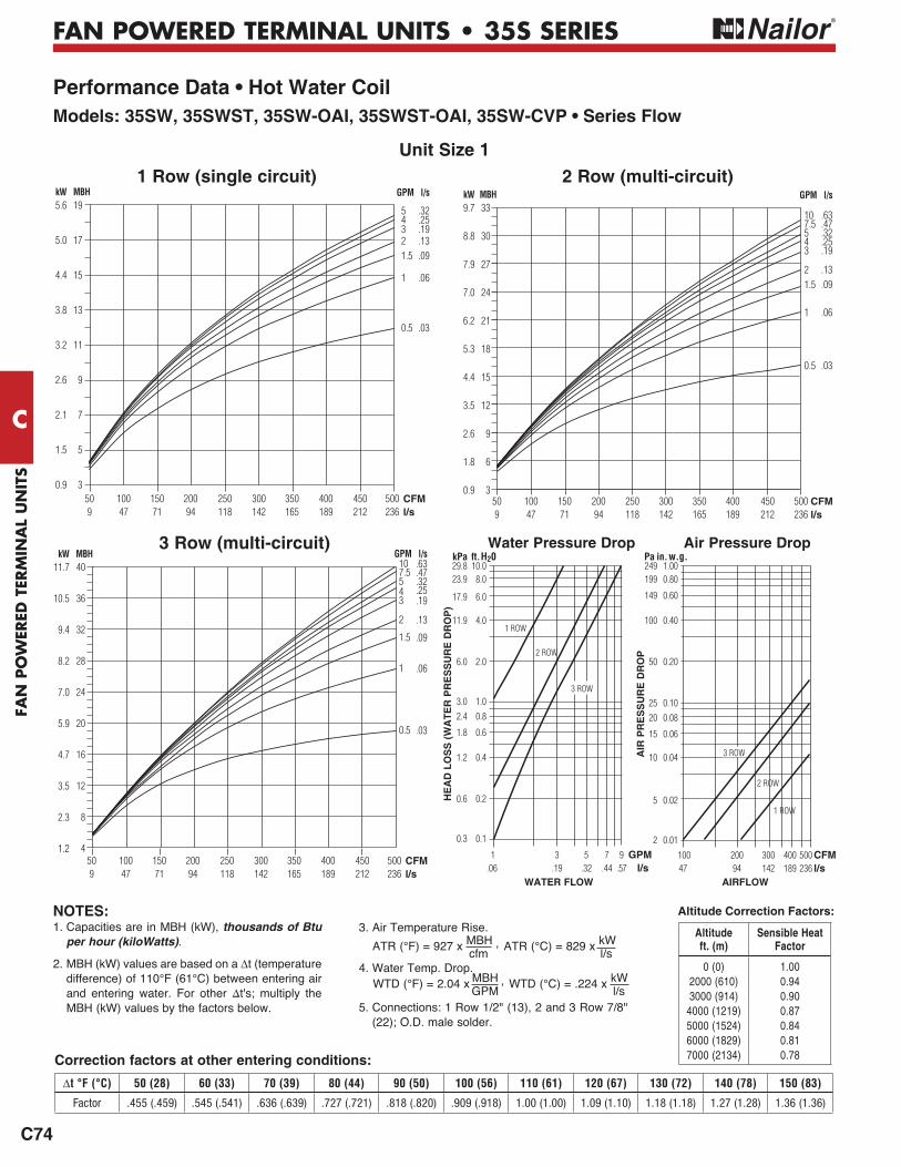
FAN POWERED TERMINAL UNITS • 35S SERIES
Unit Size 1
2 Row (multi-circuit)1 Row (single circuit)
33
30
27
24
21
18
15
12
9
6
3
9.7
8.8
7.9
7.0
6.2
5.3
4.4
3.5
2.6
1.8
0.9
kW MBH
50 100 150 200 250 300 350 400 450 500 9 47 71 94 118 142 165 189 212 236
CFMl/s
GPM l/s
107.5543
21.5
1
0.5
.63
.47
.32
.25
.19
.13
.09
.06
.03
1 ROW
2 ROW
1 ROW
2 ROW
19
17
15
13
11
9
7
5
3
5.6
5.0
4.4
3.8
3.2
2.6
2.1
1.5
0.9
kW MBH
50 100 150 200 250 300 350 400 450 500 9 47 71 94 118 142 165 189 212 236
CFMl/s
GPM l/s
54321.5
1
0.5
.32
.25
.19
.13
.09
.06
.03
Air Pressure DropWater Pressure Drop
WATER FLOW AIRFLOW
HE
AD
LO
SS
(W
AT
ER
PR
ES
SU
RE
DR
OP
)
1 3 5 7 9 GPM.06 .19 .32 .44 .57 l/s
10.08.0
6.0
4.0
2.0
1.00.8
0.6
0.4
0.2
0.1
kPa ft. H2029.823.9
17.9
11.9
6.0
3.02.4
1.8
1.2
0.6
0.3
AIR
PR
ES
SU
RE
DR
OP
100 200 300 400 500 CFM 47 94 142 189 236 l/s
1.000.80
0.60
0.40
0.20
0.100.08
0.06
0.04
0.02
0.01
Pa in. w.g.249199
149
100
50
2520
15
10
5
2
Performance Data • Hot Water CoilModels: 35SW, 35SWST, 35SW-OAI, 35SWST-OAI, 35SW-CVP • Series Flow
3 Row (multi-circuit)40
36
32
28
24
20
16
12
8
4
11.7
10.5
9.4
8.2
7.0
5.9
4.7
3.5
2.3
1.2
kW GPM l/s107.5543
2
1.5
1
0.5
.63
.47
.32
.25
.19
.13
.09
.06
.03
MBH
50 100 150 200 250 300 350 400 450 500 9 47 71 94 118 142 165 189 212 236
CFMl/s
3 ROW
3 ROW
Altitude Correction Factors:
Correction factors at other entering conditions:
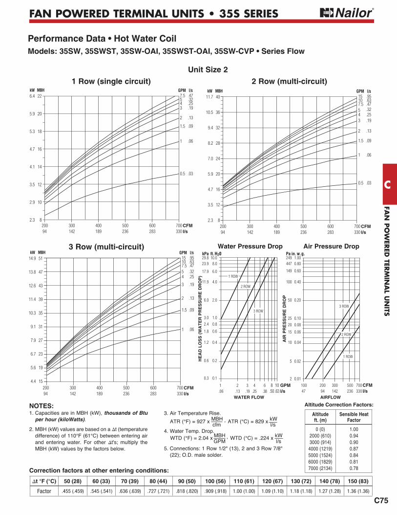
1. Capacities are in MBH (kW), thousands of Btu per hour (kiloWatts).
2. MBH (kW) values are based on a t (temperature difference) of 110°F (61°C) between entering air and entering water. For other t's; multiply the MBH (kW) values by the factors below.
3. Air Temperature Rise.
4. Water Temp. Drop.
5. Connections: 1 Row 1/2" (13), 2 and 3 Row 7/8" (22); O.D. male solder.
ATR (°C) = 829 x kW l/s
ATR (°F) = 927 x MBH , cfm
WTD (°C) = .224 x kW l/s
WTD (°F) = 2.04 x MBH , GPM
NOTES:Altitude ft. (m)
Sensible Heat Factor
0 (0)2000 (610) 3000 (914)
4000 (1219) 5000 (1524) 6000 (1829) 7000 (2134)
1.00 0.94 0.90 0.87 0.84 0.81 0.78
t °F (°C) 50 (28) 60 (33) 70 (39) 80 (44) 90 (50) 100 (56) 110 (61) 120 (67) 130 (72) 140 (78) 150 (83)
Factor .455 (.459) .545 (.541) .636 (.639) .727 (.721) .818 (.820) .909 (.918) 1.00 (1.00) 1.09 (1.10) 1.18 (1.18) 1.27 (1.28) 1.36 (1.36)
FAN
PO
WER
ED TER
MIN
AL U
NITS
C
C75
FAN POWERED TERMINAL UNITS • 35S SERIES
Performance Data • Hot Water CoilModels: 35SW, 35SWST, 35SW-OAI, 35SWST-OAI, 35SW-CVP • Series Flow
2 Row (multi-circuit)1 Row (single circuit)
3 Row (multi-circuit)
200 300 400 500 600 700 94 142 189 236 283 330
CFMl/s
40
36
32
28
24
20
16
12
8
11.7
10.5
9.4
8.2
7.0
5.9
4.7
3.5
2.3
kW MBH GPM l/s15107.5543
2
1.5
1
0.5
.95
.63
.47
.32
.25
.19
.13
.09
.06
.03
Unit Size 2
1 ROW
2 ROW
3 ROW
1 ROW
2 ROW
3 ROW
200 300 400 500 600 700 94 142 189 236 283 330
CFMl/s
22
20
18
16
14
12
10
8
6.4
5.9
5.3
4.7
4.1
3.5
2.9
2.3
kW MBH GPM l/s7.5543
2
1.5
1
0.5
.47
.32
.25
.19
.13
.09
.06
.03
200 300 400 500 600 700 94 142 189 236 283 330
CFMl/s
51
47
43
39
35
31
27
23
19
15
14.9
13.8
12.6
11.4
10.3
9.1
7.9
6.7
5.6
4.4
kW MBH GPM l/s15107.554
3
2
1.5
1
.95
.63
.47
.32
.25
.19
.13
.09
.06
Water Pressure Drop
WATER FLOW
HE
AD
LO
SS
(W
AT
ER
PR
ES
SU
RE
DR
OP
)
1 2 3 4 6 8 10 GPM .06 .13 .19 .25 .38 .50 .63 l/s
10.08.0
6.0
4.0
2.0
1.00.8
0.6
0.4
0.2
0.1
kPa ft. H2029.823.9
17.9
11.9
6.0
3.02.4
1.8
1.2
0.6
0.3
Air Pressure Drop
AIRFLOW
100 200 300 500 700 CFM 47 94 142 236 330 l/s
AIR
PR
ES
SU
RE
DR
OP
1.000.80
0.60
0.40
0.20
0.100.08
0.06
0.04
0.02
0.01
Pa in. w.g.249447
149
100
50
2520
15
10
5
2
Correction factors at other entering conditions:
1. Capacities are in MBH (kW), thousands of Btu per hour (kiloWatts).
2. MBH (kW) values are based on a t (temperature difference) of 110°F (61°C) between entering air and entering water. For other t's; multiply the MBH (kW) values by the factors below.
3. Air Temperature Rise.
4. Water Temp. Drop.
5. Connections: 1 Row 1/2" (13), 2 and 3 Row 7/8" (22); O.D. male solder.
ATR (°C) = 829 x kW l/s
ATR (°F) = 927 x MBH , cfm
WTD (°C) = .224 x kW l/s
WTD (°F) = 2.04 x MBH , GPM
NOTES:
50 (28) 60 (33) 70 (39) 80 (44) 90 (50) 100 (56) 110 (61) 120 (67) 130 (72) 140 (78) 150 (83)
Factor .455 (.459) .545 (.541) .636 (.639) .727 (.721) .818 (.820) .909 (.918) 1.00 (1.00) 1.09 (1.10) 1.18 (1.18) 1.27 (1.28) 1.36 (1.36)
Altitude Correction Factors:
Altitude ft. (m)
Sensible Heat Factor
0 (0)2000 (610) 3000 (914)
4000 (1219) 5000 (1524) 6000 (1829) 7000 (2134)
1.00 0.94 0.90 0.87 0.84 0.81 0.78

FAN
PO
WER
ED T
ERM
INA
L U
NIT
S
C
C76
FAN POWERED TERMINAL UNITS • 35S SERIES
Performance Data • Hot Water CoilModels: 35SW, 35SWST, 35SW-OAI, 35SWST-OAI, 35SW-CVP • Series Flow
2 Row (multi-circuit)
300 500 700 900 1100 1300 142 236 330 425 519 613
CFMl/s
32
29
26
23
20
17
14
11
9.4
8.5
7.6
6.7
5.9
5.0
4.1
3.2
kW MBH GPM l/s7.5543
2
1.5
1
0.5
.47
.32
.25
.19
.13
.09
.06
.03
1 Row (single circuit)
3 Row (multi-circuit)
300 500 700 900 1100 1300 142 236 330 425 519 613
CFMl/s
60
55
50
45
40
35
30
25
20
15
10
17.6
16.1
14.7
13.2
11.7
10.3
8.8
7.3
5.9
4.4
2.9
kW MBH GPM l/s15107.5
54
3
2
1.5
1
0.5
.95
.63
.47
.32
.25
.19
.13
.09
.06
.03
300 500 700 900 1100 1300 142 236 330 425 519 613
CFMl/s
80
75
70
65
60
55
50
45
40
35
30
25
20
15
23.4
22.0
20.5
19.0
17.6
16.1
14.7
13.2
11.7
10.3
8.8
7.3
5.9
4.4
kW MBH GPM l/s15107.5
54
3
2
1.5
1
0.5
.95
.63
.47
.32
.25
.19
.13
.09
.06
.03
Unit Size 3
1 ROW
2 ROW
3 ROW
1 ROW
2 ROW
3 ROW
Air Pressure DropWater Pressure Drop
WATER FLOW AIRFLOW
HE
AD
LO
SS
(W
AT
ER
PR
ES
SU
RE
DR
OP
)
1 2 3 4 6 8 10 GPM .06 .13 .19 .25 .38 .50 .63 l/s
10.08.0
6.0
4.0
2.0
1.00.8
0.6
0.4
0.2
0.1
kPa ft. H2029.823.9
17.9
11.9
6.0
3.02.4
1.8
1.2
0.6
0.3
100 200 400 600 1000 2000 CFM 47 94 189 283 472 944 l/s
AIR
PR
ES
SU
RE
DR
OP
1.000.80
0.60
0.40
0.20
0.100.08
0.06
0.04
0.02
0.01
Pa in. w.g.249447
149
100
50
2520
15
10
5
2
Correction factors at other entering conditions:
1. Capacities are in MBH (kW), thousands of Btu per hour (kiloWatts).
2. MBH (kW) values are based on a t (temperature difference) of 110°F (61°C) between entering air and entering water. For other t's; multiply the MBH (kW) values by the factors below.
3. Air Temperature Rise.
4. Water Temp. Drop.
5. Connections: 1 Row 1/2" (13), 2 and 3 Row 7/8" (22); O.D. male solder.
ATR (°C) = 829 x kW l/s
ATR (°F) = 927 x MBH , cfm
WTD (°C) = .224 x kW l/s
WTD (°F) = 2.04 x MBH , GPM
NOTES:
50 (28) 60 (33) 70 (39) 80 (44) 90 (50) 100 (56) 110 (61) 120 (67) 130 (72) 140 (78) 150 (83)
Factor .455 (.459) .545 (.541) .636 (.639) .727 (.721) .818 (.820) .909 (.918) 1.00 (1.00) 1.09 (1.10) 1.18 (1.18) 1.27 (1.28) 1.36 (1.36)
Altitude Correction Factors:
Altitude ft. (m)
Sensible Heat Factor
0 (0)2000 (610) 3000 (914)
4000 (1219) 5000 (1524) 6000 (1829) 7000 (2134)
1.00 0.94 0.90 0.87 0.84 0.81 0.78
FAN
PO
WER
ED TER
MIN
AL U
NITS
C
C77
FAN POWERED TERMINAL UNITS • 35S SERIES
Performance Data • Hot Water CoilModels: 35SW, 35SWST, 35SW-OAI, 35SWST-OAI, 35SW-CVP • Series Flow
2 Row (multi-circuit)
600 800 1000 1200 1400 1600 1800 283 378 472 566 661 755 849
CFMl/s
47
43
39
35
31
27
23
19
15
13.8
12.6
11.4
10.3
9.1
7.9
6.7
5.6
4.4
kW MBH GPM l/s
7.5
5
4
3
2
1.5
1
0.5
.47
.32
.25
.19
.13
.09
.06
.03
1 Row (multi-circuit)
3 Row (multi-circuit)
600 800 1000 1200 1400 1600 1800 283 378 472 566 661 755 849
CFMl/s
82
77
72
67
62
57
52
47
42
37
32
27
22
17
24.0
22.6
21.1
19.6
18.2
16.7
15.2
13.8
12.3
10.8
9.4
7.9
6.4
5.0
kW MBH GPM l/s
107.5
5
4
3
2
1.5
1
0.5
.63
.47
.32
.25
.19
.13
.09
.06
.03
600 800 1000 1200 1400 1600 1800283 378 472 566 661 755 849
CFMl/s
112
102
92
82
72
62
52
42
32
22
32.8
29.9
27.0
24.0
21.1
18.2
15.2
12.3
9.4
6.4
kW MBH GPM l/s
1510
7.5
5
4
3
2
1.5
1
0.5
.95
.63
.47
.32
.25
.19
.13
.09
.06
.03
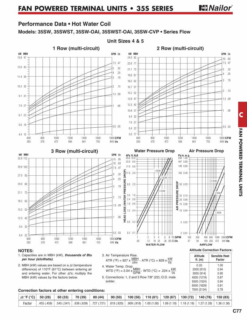
Unit Sizes 4 & 5
1 ROW
2 ROW
3 ROW
1 ROW
2 ROW
3 ROW
Water Pressure Drop
WATER FLOW
HE
AD
LO
SS
(W
AT
ER
PR
ES
SU
RE
DR
OP
)
1 2 3 4 6 8 10 GPM .06 .13 .19 .25 .38 .50 .63 l/s
10.08.0
6.0
4.0
2.0
1.00.8
0.6
0.4
0.2
0.1
kPa ft. H2029.823.9
17.9
11.9
6.0
3.02.4
1.8
1.2
0.6
0.3
Air Pressure Drop
AIRFLOW
100 200 400 600 1000 2000 CFM 47 94 189 283 472 944 l/s
AIR
PR
ES
SU
RE
DR
OP
1.000.80
0.60
0.40
0.20
0.100.08
0.06
0.04
0.02
0.01
Pa in. w.g.249447
149
100
50
2520
15
10
5
2
NOTES:
Correction factors at other entering conditions:
1. Capacities are in MBH (kW), thousands of Btu per hour (kiloWatts).
2. MBH (kW) values are based on a t (temperature difference) of 110°F (61°C) between entering air and entering water. For other t's; multiply the MBH (kW) values by the factors below.
3. Air Temperature Rise.
4. Water Temp. Drop.
5. Connections: 1, 2 and 3 Row 7/8" (22); O.D. male solder.
ATR (°C) = 829 x kW l/s
ATR (°F) = 927 x MBH , cfm
WTD (°C) = .224 x kW l/s
WTD (°F) = 2.04 x MBH , GPM
50 (28) 60 (33) 70 (39) 80 (44) 90 (50) 100 (56) 110 (61) 120 (67) 130 (72) 140 (78) 150 (83)
Factor .455 (.459) .545 (.541) .636 (.639) .727 (.721) .818 (.820) .909 (.918) 1.00 (1.00) 1.09 (1.10) 1.18 (1.18) 1.27 (1.28) 1.36 (1.36)
Altitude Correction Factors:
Altitude ft. (m)
Sensible Heat Factor
0 (0)2000 (610) 3000 (914)
4000 (1219) 5000 (1524) 6000 (1829) 7000 (2134)
1.00 0.94 0.90 0.87 0.84 0.81 0.78
FAN
PO
WER
ED T
ERM
INA
L U
NIT
S
C
C78
FAN POWERED TERMINAL UNITS • 35S SERIES
Performance Data • Hot Water CoilModels: 35SW, 35SWST, 35SW-OAI, 35SWST-OAI, 35SW-CVP • Series Flow
2 Row (multi-circuit)
1000 1200 1400 1600 1800 2000 2200 472 566 661 755 849 944 1038
CFMl/s
62
56
50
44
38
32
26
20
18.2
16.4
14.7
12.9
11.1
9.4
7.6
5.9
kW MBH GPM l/s
15107.5
54
3
2
1.5
1
.95
.63
.47
.32
.25
.19
.13
.09
.06
1 Row (multi-circuit)
3 Row (multi-circuit)
1000 1200 1400 1600 1800 2000 2200 472 566 661 755 849 944 1038
CFMl/s
110
100
90
80
70
60
50
40
30
32.2
29.3
26.4
23.4
20.5
17.6
14.7
11.7
8.8
kW MBH GPM l/s
15
10
7.5
5
4
3
2
1.5
1
.95
.63
.47
.32
.25
.19
.13
.09
.06
1000 1200 1400 1600 1800 2000 2200 472 566 661 755 849 944 1038
CFMl/s
140
130
120
110
100
90
80
70
60
50
40
30
41.0
38.1
35.2
32.2
29.3
26.4
23.4
20.5
17.6
14.7
11.7
8.8
kW MBH GPM l/s15
10
7.5
5
4
3
2
1.5
1
.95
.63
.47
.32
.25
.19
.13
.09
.06
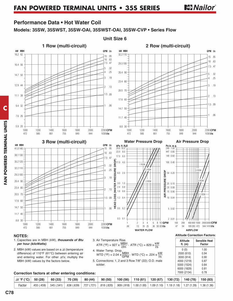
Unit Size 6
1 ROW
2 ROW
3 ROW
1 ROW
2 ROW
3 ROW
Air Pressure DropWater Pressure Drop
WATER FLOW AIRFLOW
HE
AD
LO
SS
(W
AT
ER
PR
ES
SU
RE
DR
OP
)
1 2 3 4 6 8 10 GPM .06 .13 .19 .25 .38 .50 .63 l/s
10.08.0
6.0
4.0
2.0
1.00.8
0.6
0.4
0.2
0.1
kPa ft. H2029.823.9
17.9
11.9
6.0
3.02.4
1.8
1.2
0.6
0.3
100 200 400 600 1000 2000 3000 CFM 47 94 189 283 472 944 1416 l/s
AIR
PR
ES
SU
RE
DR
OP
1.000.80
0.60
0.40
0.20
0.100.08
0.06
0.04
0.02
0.01
Pa in. w.g.249447
149
100
50
2520
15
10
5
2
Correction factors at other entering conditions:
1. Capacities are in MBH (kW), thousands of Btu per hour (kiloWatts).
2. MBH (kW) values are based on a t (temperature difference) of 110°F (61°C) between entering air and entering water. For other t's; multiply the MBH (kW) values by the factors below.
3. Air Temperature Rise.
4. Water Temp. Drop.
5. Connections: 1, 2 and 3 Row 7/8" (22); O.D. male solder.
ATR (°C) = 829 x kW l/s
ATR (°F) = 927 x MBH , cfm
WTD (°C) = .224 x kW l/s
WTD (°F) = 2.04 x MBH , GPM
NOTES:
50 (28) 60 (33) 70 (39) 80 (44) 90 (50) 100 (56) 110 (61) 120 (67) 130 (72) 140 (78) 150 (83)
Factor .455 (.459) .545 (.541) .636 (.639) .727 (.721) .818 (.820) .909 (.918) 1.00 (1.00) 1.09 (1.10) 1.18 (1.18) 1.27 (1.28) 1.36 (1.36)
Altitude Correction Factors:
Altitude ft. (m)
Sensible Heat Factor
0 (0)2000 (610) 3000 (914)
4000 (1219) 5000 (1524) 6000 (1829) 7000 (2134)
1.00 0.94 0.90 0.87 0.84 0.81 0.78
FAN
PO
WER
ED TER
MIN
AL U
NITS
C
C79
FAN POWERED TERMINAL UNITS • 35S SERIES
Performance Data • Hot Water CoilModels: 35SW, 35SWST, 35SW-OAI, 35SWST-OAI, 35SW-CVP • Series Flow
2 Row (multi-circuit)
1300 1600 1900 2200 2500 2800 3100 3400 613 755 897 1038 1180 1321 1463 1604
CFMl/s
90
80
70
60
50
40
30
26.4
23.4
20.5
17.6
14.7
11.7
8.8
kW MBH GPM l/s15
10
7.5
5
4
3
2
1.5
1
.95
.63
.47
.32
.25
.19
.13
.09
.06
1 Row (multi-circuit)
3 Row (multi-circuit)
155
145
135
125
115
105
95
85
75
65
55
45
35
45.4
42.5
39.6
36.6
33.7
30.8
27.8
24.9
22.0
19.0
16.1
13.2
10.3
kW MBH GPM l/s15
10
7.5
5
4
3
2
1.5
1
.95
.63
.47
.32
.25
.19
.13
.09
.06
1300 1600 1900 2200 2500 2800 3100 3400 613 755 897 1038 1180 1321 1463 1604
CFMl/s
200
190
180
170
160
150
140
130
120
110
100
90
80
70
60
50
40
58.6
55.7
52.8
49.8
46.9
44.0
41.0
38.1
35.2
32.2
29.3
26.4
23.4
20.5
17.6
14.7
11.7
kW MBH GPM l/s15
10
7.5
5
4
3
2
1.5
1
.95
.63
.47
.32
.25
.19
.13
.09
.06
1300 1600 1900 2200 2500 2800 3100 3400 613 755 897 1038 1180 1321 1463 1604
CFMl/s
1 ROW
2 ROW
3 ROW
1 ROW
2 ROW
3 ROW
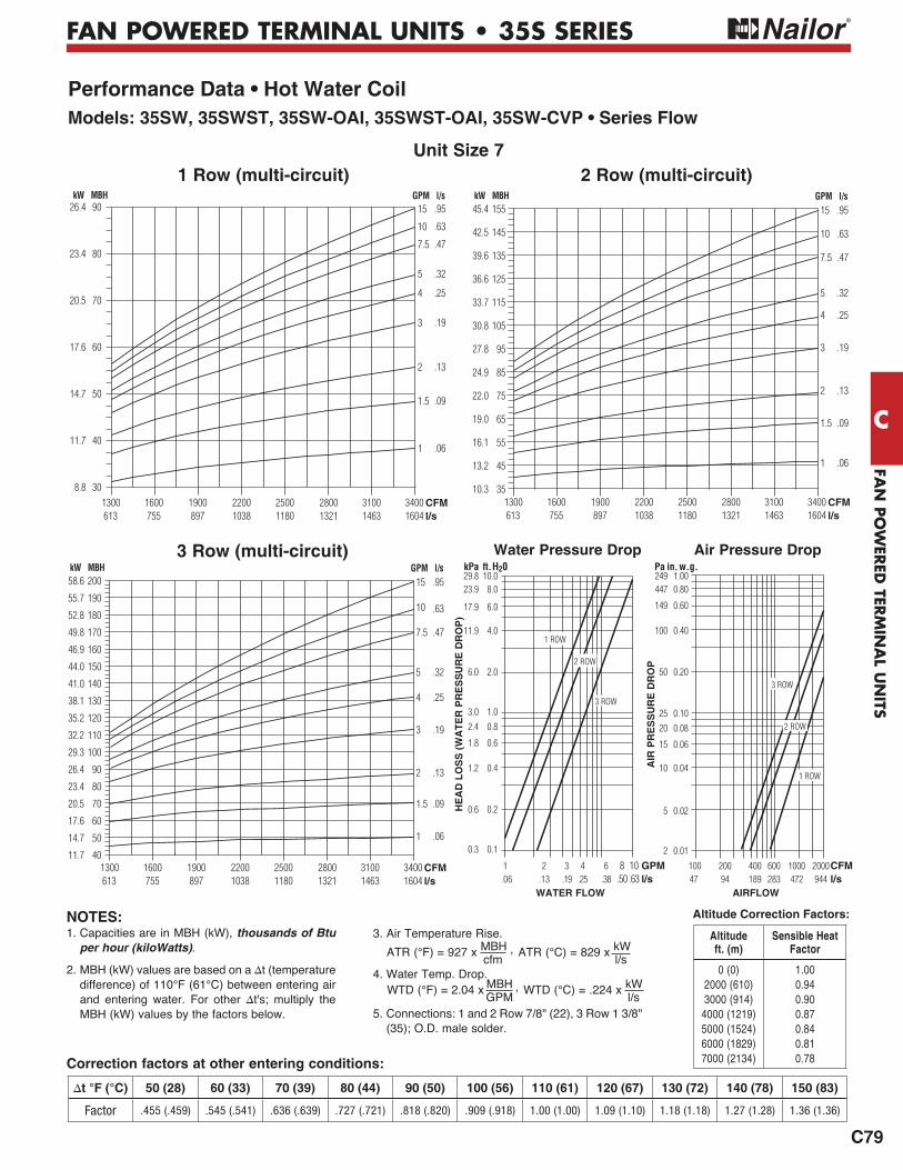
Unit Size 7
Water Pressure Drop
WATER FLOW
HE
AD
LO
SS
(W
AT
ER
PR
ES
SU
RE
DR
OP
)
1 2 3 4 6 8 10 GPM .06 .13 .19 .25 .38 .50 .63 l/s
10.08.0
6.0
4.0
2.0
1.00.8
0.6
0.4
0.2
0.1
kPa ft. H2029.823.9
17.9
11.9
6.0
3.02.4
1.8
1.2
0.6
0.3
Air Pressure Drop
AIRFLOW
100 200 400 600 1000 2000 CFM 47 94 189 283 472 944 l/s
AIR
PR
ES
SU
RE
DR
OP
1.000.80
0.60
0.40
0.20
0.100.08
0.06
0.04
0.02
0.01
Pa in. w.g.249447
149
100
50
2520
15
10
5
2
Correction factors at other entering conditions:
1. Capacities are in MBH (kW), thousands of Btu per hour (kiloWatts).
2. MBH (kW) values are based on a t (temperature difference) of 110°F (61°C) between entering air and entering water. For other t's; multiply the MBH (kW) values by the factors below.
3. Air Temperature Rise.
4. Water Temp. Drop.
5. Connections: 1 and 2 Row 7/8" (22), 3 Row 1 3/8" (35); O.D. male solder.
ATR (°C) = 829 x kW l/s
ATR (°F) = 927 x MBH , cfm
WTD (°C) = .224 x kW l/s
WTD (°F) = 2.04 x MBH , GPM
NOTES:
50 (28) 60 (33) 70 (39) 80 (44) 90 (50) 100 (56) 110 (61) 120 (67) 130 (72) 140 (78) 150 (83)
Factor .455 (.459) .545 (.541) .636 (.639) .727 (.721) .818 (.820) .909 (.918) 1.00 (1.00) 1.09 (1.10) 1.18 (1.18) 1.27 (1.28) 1.36 (1.36)
Altitude Correction Factors:
Altitude ft. (m)
Sensible Heat Factor
0 (0)2000 (610) 3000 (914)
4000 (1219) 5000 (1524) 6000 (1829) 7000 (2134)
1.00 0.94 0.90 0.87 0.84 0.81 0.78
FAN
PO
WER
ED T
ERM
INA
L U
NIT
S
C
C80
FAN POWERED TERMINAL UNITS • 37S SERIES
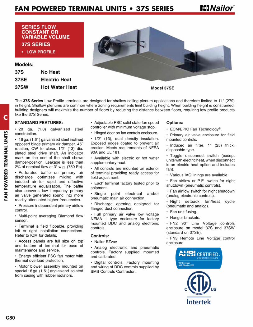
SERIES FLOWCONSTANT ORVARIABLE VOLUME37S SERIES• LOW PROFILE
Models:
37S No Heat
37SE Electric Heat
37SW Hot Water Heat
STANDARD FEATURES:
• 20 ga. (1.0) galvanized steel construction.
• 16 ga. (1.61) galvanized steel inclined opposed blade primary air damper. 45O
rotation, CW to close. 1/2" (13) dia. plated steel drive shaft. An indicator mark on the end of the shaft shows damper-position. Leakage is less than
discharge optimizes mixing with induced air for rapid and effective
also converts low frequency primary air valve generated sound into more readily attenuated higher frequencies.
control.
sensor.
left or right installation connections. Refer to IOM for details.
• Access panels are full size on top and bottom of terminal for ease of maintenance and service.
thermal overload protection.
• Motor blower assembly mounted on special 16 ga. (1.61) angles and isolated from casing with rubber isolators.
• Adjustable PSC solid state fan speed controller with minimum voltage stop.
• Hinged door on fan controls enclosure.
• 1/2" (13), dual density insulation. Exposed edges coated to prevent air erosion. Meets requirements of NFPA 90A and UL 181.
• Available with electric or hot water supplementary heat.
• All controls are mounted on exterior of terminal providing ready access for
• Each terminal factory tested prior to shipment.
• Single point electrical and/or pneumatic main air connection.
• Discharge opening designed for
• Full primary air valve low voltage NEMA 1 type enclosure for factory mounted DDC and analog electronic controls.
Controls:• Nailor EZvav
• Analog electronic and pneumatic controls. Factory supplied, mounted and calibrated.
• Digital controls. Factory mounting and wiring of DDC controls supplied by BMS Controls Contractor.
Options:
• ECM/EPIC Fan Technology®.
mounted controls.
disposable type.
• Toggle disconnect switch (except units with electric heat, when disconnect is an electric heat option and includes fan).
• Various IAQ linings are available.
shutdown (pneumatic controls).
(analog electronic controls).
• Night setback fan/heat cycle (pneumatic and analog).
• Fan unit fusing.
• Hanger brackets.
• FN2 90° Line Voltage controls enclosure on model 37S and 37SW (standard on 37SE).
• FN3 Remote Line Voltage control enclosure.
The 37S Seriesin height. Shallow plenums are common where zoning requirements limit building height. When building height is constrained,
like the 37S Series.
Model 37SE

FAN
PO
WER
ED TER
MIN
AL U
NITS
C
C81
FAN POWERED TERMINAL UNITS • 37S SERIES
DimensionsModel Series 37S • Low Profile • Series Flow • Unit Sizes 1 – 3
Dimensional Data
Unit Size
Inlet Size
W LInduced Air
Inlet IW x IH
OutletDischargeDW x DH
FilterSize
1 4, 5, 6, 8 (102, 127, 152, 203)
19 (483)
36 (914)
6 x 8 (152 x 203)
10 3/8 x 6 7/8 (264 x 175)
8 x 10 (203 x 254)
2 6, 8, 10 (152, 203, 254)
26 1/2 (673)
40 1/4 (1022)
15 3/4 x 8 (400 x 203)
11 3/8 x 6 7/8 (289 x 175)
18 x 10 (457 x 254)
3 6, 8, 10 (152, 203, 254)
26 1/2 (673)
40 1/4 (1022)
15 3/4 x 8 (400 x 203)
12 3/8 x 6 7/8 (314 x 175)
18 x 10 (457 x 254)
6 3/4"(171)
INDUCEDAIR
L
OPTIONALINDUCED AIRINLET FILTER
IW
IH
OPTIONALPRIMARY AIR VALVE
CONTROLSENCLOSURE
HINGED FANCONTROLSENCLOSURE
DIA. =NOM. – 1/8" (3)
DRIVESHAFT
MULTI-POINTFLOW SENSOR
PRIMARY
AIR
FAN
DW
DH2"
(51)
W
10" (254)
5 4/5" (147)
5"(127)
11"(279)
8"(203)
5 1/2"(140)
2"(51)
6 1/4"(159)
OPTIONAL90° FN2 HINGEDFAN CONTROLS
ENCLOSURE
15"(381)14" (356)

FAN
PO
WER
ED T
ERM
INA
L U
NIT
S
C
C82
FAN POWERED TERMINAL UNITS • 37S SERIES
DimensionsModel Series 37S • Low Profile • Series Flow • Unit Size 4
Dimensional Data
Unit Size
Inlet Size
W L B PInduced Air
Inlet IW x IH
OutletDischargeDW x DH
FilterSize
4 10 (254) Round 14 x 10 (356 x 254) Rect.
44 (1118)
36 1/2 (927)
9 3/4 (248)
2 1/16 (52)
12 x 9 (305 x 229)
Qty. of 2
24 1/2 x 6 7/8 (622 x 175)
14 x 10 (356 x 254)
Qty. of 2
W2
INDUCED
AIR
INDUCED
AIR
PRIMARY
AIR
DRIVESHAFT
IH
MULTI-POINTFLOW
SENSOR
OPTIONALINDUCED AIRINLET FILTER
NOM. – 1/8" (3)
11" (279)
DH
PL
W
11 1/4"(286)
11 1/4"(286)
B
DW
OPTIONALPRIMARY AIR
VALVE CONTROLSENCLOSURE
HINGED FANCONTROLSENCLOSURE
14"(356)
10"(254)
5 3/4" (146)
PRIMARY
AIR
5 1/2"(140)
H2
FAN
FAN
IW
15"(381)
6 3/4"(171)
OPTIONAL90° FN2 HINGEDFAN CONTROLS
ENCLOSURE 11" (279)
FAN
PO
WER
ED TER
MIN
AL U
NITS
C
C83
FAN POWERED TERMINAL UNITS • 37S SERIES
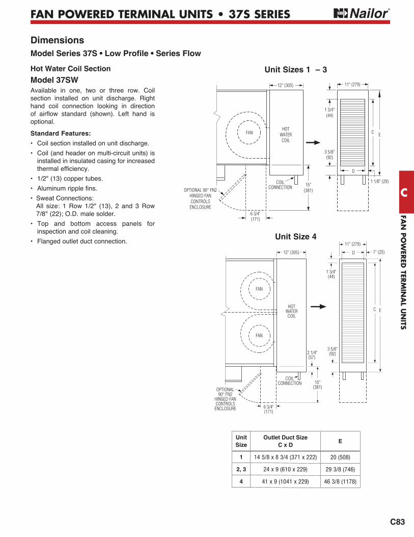
Hot Water Coil Section
Model 37SWAvailable in one, two or three row. Coil section installed on unit discharge. Right hand coil connection looking in direction
optional.
Standard Features:
• Coil section installed on unit discharge.
• Coil (and header on multi-circuit units) is installed in insulated casing for increased
• 1/2" (13) copper tubes.
• Sweat Connections:All size: 1 Row 1/2" (13), 2 and 3 Row 7/8" (22); O.D. male solder.
• Top and bottom access panels for inspection and coil cleaning.
• Flanged outlet duct connection.
DimensionsModel Series 37S • Low Profile • Series Flow
Unit Size
Outlet Duct SizeC x D
E
1 14 5/8 x 8 3/4 (371 x 222) 20 (508)
2, 3 24 x 9 (610 x 229) 29 3/8 (746)
4 41 x 9 (1041 x 229) 46 3/8 (1178)
12" (305)
COILCONNECTION
1 3/4"(44)
D
C E
1 1/8" (29)
11" (279)
3 5/8"(92)
FANHOT
WATERCOIL
6 3/4"(171)
OPTIONAL 90° FN2HINGED FAN CONTROLSENCLOSURE
15"(381)
Unit Sizes 1 – 3
Unit Size 4
6 3/4"(171)
15"(381)OPTIONAL
90° FN2HINGED FANCONTROLSENCLOSURE
12" (305)
1 3/4"(44)
1" (25)D
FAN
FAN
C E
2 1/4" (57)
11" (279)
3 5/8"(92)
COILCONNECTION
HOTWATERCOIL

FAN
PO
WER
ED T
ERM
INA
L U
NIT
S
C
C84
FAN POWERED TERMINAL UNITS • 37S SERIES
Electric Coil Section
Model 37SE Standard Features:
• Controls enclosure incorporates a hinged access door opening upstream that helps ensure NEC clearance requirements and reduces footprint.
• Coil installed on unit discharge.
• Insulated coil element wrapper.
• Automatic reset high limit cut-outs
(one per element).
• Single point electrical connection for entire terminal unit.
• Magnetic contactors per stage.
• Class A 80/20 Ni/Cr wire.
• Flanged outlet duct connection.
• Terminal unit with coil is ETL Listed as an assembly.
• Controls mounted as standard on RH side as shown. Terminals ordered with LH controls (optional) are inverted.
Standard Supply Voltage (60 Hz):
• Single phase: 120, 208, 240 & 277V.
• Three phase: 208, 480 (4 wire wye) and 600V (dual point connection).
Options:
• Toggle disconnect switch (includes fan).
• Door interlock disconnect switch.
• Mercury contactors.
• Power circuit fusing.
• Dust tight construction.
• Manual reset secondary thermal cut out.
• SCR Control.
DimensionsModel Series 37S • Low Profile • Series Flow
Unit Sizes 1 – 3
Unit Size 4
ELECTRICCOIL AND90° FN2
HINGED FAN CONTROLS ENCLOSURE(STANDARD)
FAN
F
G1"(25)
K
15"(381)
M
15 3/8"(391)
6 3/4"(171)
11" (279)
11 1/2"(292)
ELECTRICHEATER
HINGED FOR ELEMENTREMOVAL
2" (51)
HEATER
K
11"(279)
F
G
15"(381)
FAN
FAN
6 3/4"(171)
37 3/8"(949)
1 1/2"(38)
HINGED FORELEMENT REMOVAL
1"(25)
11 1/2" (292)
8 1/2" (216)
ELECTRICCOIL AND90° FN2
HINGED FAN CONTROLS ENCLOSURE(STANDARD)
Unit Size
Outlet Duct SizeF x G
M K
1
12 3/8 x 9(314 x 229)
3 5/8 (92) 35 7/8 (911)
2 11 1/8 (283) 43 1/2 (1105)
3 11 1/8 (283) 43 1/2 (1105)
4 25 x 8 (635 x 203) — 52 3/8 (1330)

FAN
PO
WER
ED TER
MIN
AL U
NITS
FAN POWERED TERMINAL UNITS •
C
C85
FAN POWERED TERMINAL UNITS • 37S SERIES
Performance DataPSC Motor Fan Curves – Airflow vs. Downstream Static Pressure37S Series • Low Profile • Series Flow
Unit Size 2 Unit Size 31100
1000
900
800
700
600
500
400
300
AIR
FL
OW
900
800
700
600
500
400
300
200
100A
IRF
LO
W
MAXIMUM
MINIMUM
MINIMUM
MAXIMUM
425
378
330
283
236
189
142
94
47
l/s CFM
Unit Size 42200
2100
2000
1900
1800
1700
1600
1500
1400
1300
1200
1100
1000
900
800
AIR
FL
OW
MAXIMUM
l/s CFM
l/s CFM
519
472
425
378
330
283
236
189
142
1038
991
944
897
849
802
755
708
661
613
566
519
472
425
378
MINIMUM
Electrical Data
FLA = Full load amperage.All motors are single phase/60 Hz.
• Fan Curves shown are applicable to 120, 208, 240 and 277 volt, single phase PSC motors.
0.0 0.1 0.2 0.3 0.4 0.5 "w.g. 0 25 50 75 100 125 Pa DISCHARGE STATIC PRESSURE
0.0 0.1 0.2 0.3 0.4 0.5 "w.g. 0 25 50 75 100 125 Pa DISCHARGE STATIC PRESSURE
ELECTRIC HEAT OR1 OR 2 ROW HW COIL
ELECTRIC HEAT OR1 ROW HW COIL
2 ROW HW COIL
0.0 0.1 0.2 0.3 0.4 0.5 "w.g. 0 25 50 75 100 125 Pa DISCHARGE STATIC PRESSURE
ELECTRIC HEAT OR1 OR 2 ROW HW COIL
Unit Size
PSC Motor FLAMotor HP 120V 208V 240V 277V
2 1/6 4.8 1.8 1.8 1.53 1/4 5.3 3.6 3.6 1.84 2@1/4 10.6 7.2 7.2 3.7
FAN
PO
WER
ED T
ERM
INA
L U
NIT
S
C
FAN POWERED TERMINAL UNITS •
C86
FAN POWERED TERMINAL UNITS • 37S SERIES
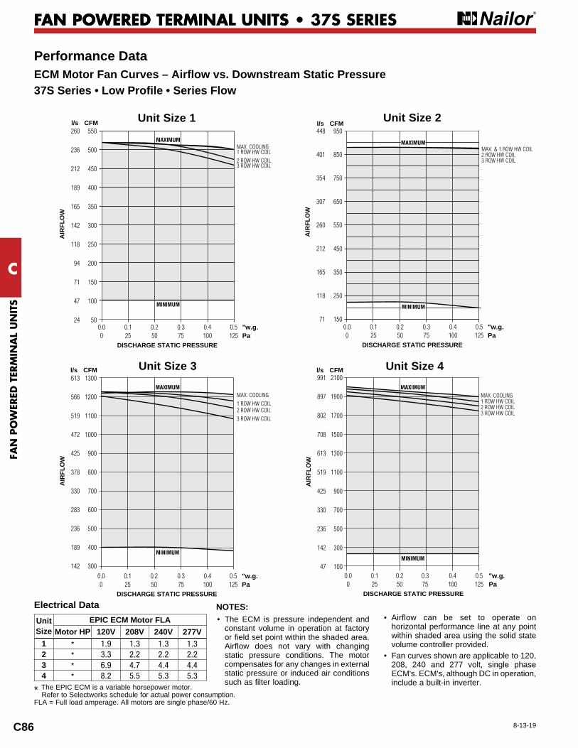
Performance DataECM Motor Fan Curves – Airflow vs. Downstream Static Pressure37S Series • Low Profile • Series Flow
Unit Size
EPIC ECM Motor FLAMotor HP 120V 208V 240V 277V
1 * 1.9 1.3 1.3 1.32 * 3.3 2.2 2.2 2.23 * 6.9 4.7 4.4 4.44 * 8.2 5.5 5.3 5.3
NOTES:• The ECM is pressure independent and
constant volume in operation at factory or field set point within the shaded area. Airflow does not vary with changing static pressure conditions. The motor compensates for any changes in external static pressure or induced air conditions such as filter loading.
• Airflow can be set to operate on horizontal performance line at any point within shaded area using the solid state volume controller provided.
• Fan curves shown are applicable to 120, 208, 240 and 277 volt, single phase ECM's. ECM's, although DC in operation, include a built-in inverter.
Electrical Data
* The EPIC ECM is a variable horsepower motor. Refer to Selectworks schedule for actual power consumption.
FLA = Full load amperage. All motors are single phase/60 Hz.
Unit Size 42100
1900
1700
1500
1300
1100
900
700
500
300
100
MAXIMUM
MINIMUM
991
897
802
708
613
519
425
330
236
142
47
AIR
FLO
W
l/s CFM
0.0 0.1 0.2 0.3 0.4 0.5 "w.g. 0 25 50 75 100 125 Pa DISCHARGE STATIC PRESSURE
Unit Size 1 550
500
450
400
350
300
250
200
150
100
50
AIR
FLO
W
MAXIMUM
l/s CFM260
236
212
189
165
142
118
94
71
47
24 0.0 0.1 0.2 0.3 0.4 0.5 "w.g. 0 25 50 75 100 125 Pa
DISCHARGE STATIC PRESSURE
MINIMUM
Unit Size 2 950
850
750
650
550
450
350
250
150
AIR
FLO
W
MAXIMUM
l/s CFM448
401
354
307
260
212
165
118
71 0.0 0.1 0.2 0.3 0.4 0.5 "w.g. 0 25 50 75 100 125 Pa DISCHARGE STATIC PRESSURE
MINIMUM
Unit Size 3 1300
1200
1100
1000
900
800
700
600
500
400
300
613
566
519
472
425
378
330
283
236
189
142
AIR
FLO
W
l/s CFM
0.0 0.1 0.2 0.3 0.4 0.5 "w.g. 0 25 50 75 100 125 Pa DISCHARGE STATIC PRESSURE
MAXIMUM
MINIMUM
MAX. COOLING1 ROW HW COIL2 ROW HW COIL3 ROW HW COIL
8-13-19
MAX. COOLING1 ROW HW COIL2 ROW HW COIL3 ROW HW COIL
MAX. COOLING1 ROW HW COIL2 ROW HW COIL3 ROW HW COIL
MAX. & 1 ROW HW COIL2 ROW HW COIL3 ROW HW COIL
FAN
PO
WER
ED TER
MIN
AL U
NITS
FAN POWERED TERMINAL UNITS •
C
C87
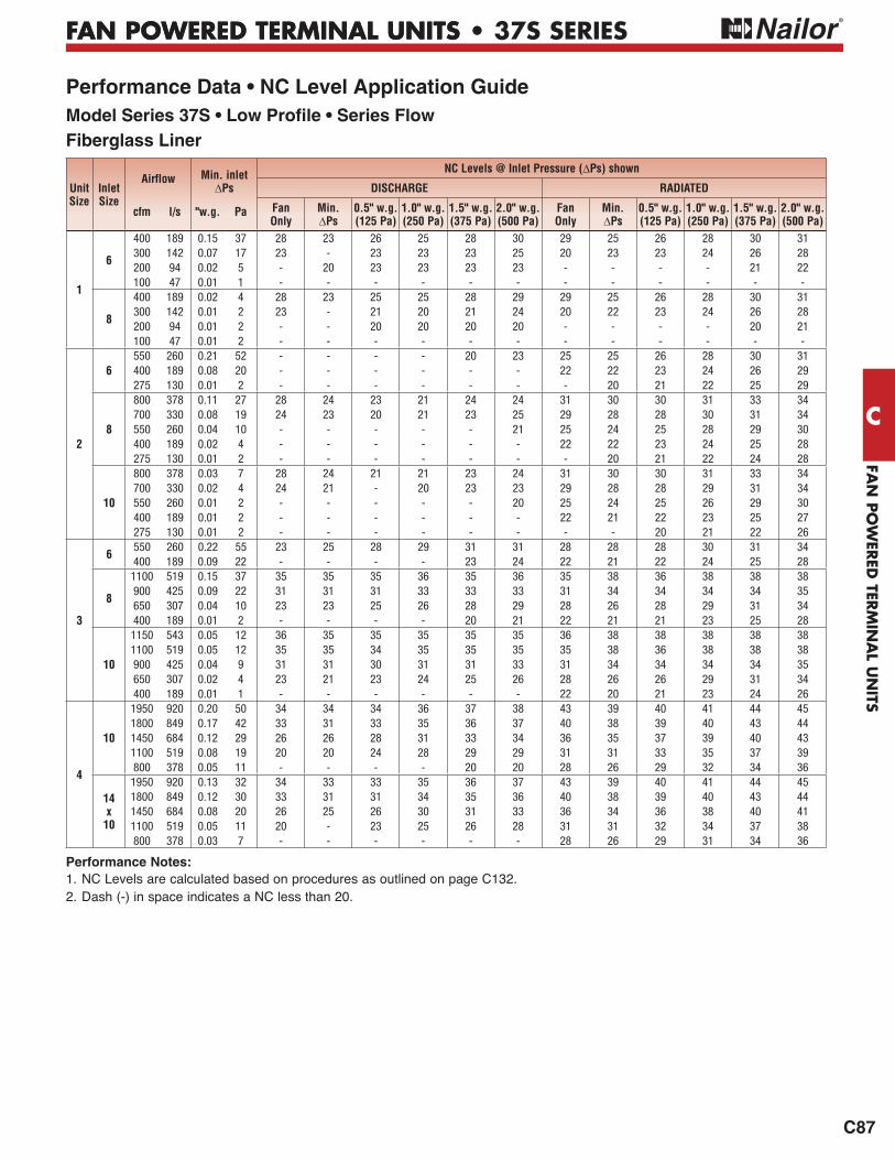
FAN POWERED TERMINAL UNITS • 37S SERIES
Performance Data • NC Level Application GuideModel Series 37S • Low Profile • Series FlowFiberglass Liner UnitSize
Inlet Size
Airflow Min. inletPs
NC Levels @ Inlet Pressure ( Ps) shown
DISCHARGE RADIATED
cfm l/s "w.g. Pa FanOnly
Min. Ps
0.5" w.g. (125 Pa)
1.0" w.g. (250 Pa)
1.5" w.g. (375 Pa)
2.0" w.g. (500 Pa)
FanOnly
Min. Ps
0.5" w.g. (125 Pa)
1.0" w.g. (250 Pa)
1.5" w.g. (375 Pa)
2.0" w.g. (500 Pa)
1
6
400 189 0.15 37 28 23 26 25 28 30 29 25 26 28 30 31300 142 0.07 17 23 - 23 23 23 25 20 23 23 24 26 28200 94 0.02 5 - 20 23 23 23 23 - - - - 21 22100 47 0.01 1 - - - - - - - - - - - -
8
400 189 0.02 4 28 23 25 25 28 29 29 25 26 28 30 31300 142 0.01 2 23 - 21 20 21 24 20 22 23 24 26 28200 94 0.01 2 - - 20 20 20 20 - - - - 20 21100 47 0.01 2 - - - - - - - - - - - -
2
6550 260 0.21 52 - - - - 20 23 25 25 26 28 30 31400 189 0.08 20 - - - - - - 22 22 23 24 26 29275 130 0.01 2 - - - - - - - 20 21 22 25 29
8
800 378 0.11 27 28 24 23 21 24 24 31 30 30 31 33 34700 330 0.08 19 24 23 20 21 23 25 29 28 28 30 31 34550 260 0.04 10 - - - - - 21 25 24 25 28 29 30400 189 0.02 4 - - - - - - 22 22 23 24 25 28275 130 0.01 2 - - - - - - - 20 21 22 24 28
10
800 378 0.03 7 28 24 21 21 23 24 31 30 30 31 33 34700 330 0.02 4 24 21 - 20 23 23 29 28 28 29 31 34550 260 0.01 2 - - - - - 20 25 24 25 26 29 30400 189 0.01 2 - - - - - - 22 21 22 23 25 27275 130 0.01 2 - - - - - - - - 20 21 22 26
3
6550 260 0.22 55 23 25 28 29 31 31 28 28 28 30 31 34400 189 0.09 22 - - - - 23 24 22 21 22 24 25 28
8
1100 519 0.15 37 35 35 35 36 35 36 35 38 36 38 38 38900 425 0.09 22 31 31 31 33 33 33 31 34 34 34 34 35650 307 0.04 10 23 23 25 26 28 29 28 26 28 29 31 34400 189 0.01 2 - - - - 20 21 22 21 21 23 25 28
10
1150 543 0.05 12 36 35 35 35 35 35 36 38 38 38 38 381100 519 0.05 12 35 35 34 35 35 35 35 38 36 38 38 38900 425 0.04 9 31 31 30 31 31 33 31 34 34 34 34 35650 307 0.02 4 23 21 23 24 25 26 28 26 26 29 31 34400 189 0.01 1 - - - - - - 22 20 21 23 24 26
4
10
1950 920 0.20 50 34 34 34 36 37 38 43 39 40 41 44 451800 849 0.17 42 33 31 33 35 36 37 40 38 39 40 43 441450 684 0.12 29 26 26 28 31 33 34 36 35 37 39 40 431100 519 0.08 19 20 20 24 28 29 29 31 31 33 35 37 39800 378 0.05 11 - - - - 20 20 28 26 29 32 34 36
14x
10
1950 920 0.13 32 34 33 33 35 36 37 43 39 40 41 44 451800 849 0.12 30 33 31 31 34 35 36 40 38 39 40 43 441450 684 0.08 20 26 25 26 30 31 33 36 34 36 38 40 411100 519 0.05 11 20 - 23 25 26 28 31 31 32 34 37 38800 378 0.03 7 - - - - - - 28 26 29 31 34 36
1. NC Levels are calculated based on procedures as outlined on page C132.2. Dash (-) in space indicates a NC less than 20.
Performance Notes:
FAN
PO
WER
ED T
ERM
INA
L U
NIT
S
C
FAN POWERED TERMINAL UNITS •
C88
FAN POWERED TERMINAL UNITS • 37S SERIES
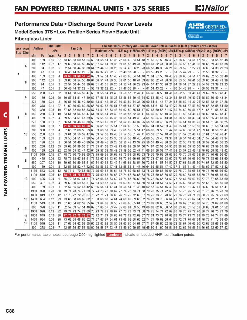
Performance Data • Discharge Sound Power LevelsModel Series 37S • Low Profile • Series Flow • Basic UnitFiberglass Liner
For performance table notes, see page C90; highlighted numbers indicate embedded AHRI certification points.
UnitSize
Inlet Size
AirflowMin. inlet
Fan OnlyFan and 100% Primary Air – Sound Power Octave Bands @ Inlet pressure ( Ps) shown
Ps Minimum Ps 0.5" w.g. (125Pa) Ps 1.0" w.g. (249Pa) Ps 1.5" w.g. (375Pa) Ps 2.0" w.g. (500Pa) Pscfm l/s "w.g. Pa 2 3 4 5 6 7 2 3 4 5 6 7 2 3 4 5 6 7 2 3 4 5 6 7 2 3 4 5 6 7 2 3 4 5 6 7
1
6
400 189 0.15 37 73 68 63 60 57 54 69 63 58 51 47 45 72 66 60 54 51 48 71 65 57 50 46 43 73 68 60 54 51 47 74 70 63 55 52 48300 142 0.07 17 69 63 58 54 50 46 65 57 52 44 39 36 69 61 55 49 44 39 69 61 52 44 38 34 69 64 56 47 41 36 70 66 59 49 43 38200 94 0.02 5 62 54 50 44 38 30 64 52 44 36 30 25 66 54 45 36 29 23 66 58 48 36 26 21 66 59 52 37 27 21 66 60 54 39 29 23100 47 0.01 1 56 48 44 37 29 - 60 46 37 29 22 - 62 49 37 28 - - 63 55 43 28 - - 61 55 47 29 - - 62 55 50 32 - -
8
400 189 0.02 4 73 68 63 60 57 54 69 63 57 51 47 45 71 65 60 54 51 48 71 64 57 50 46 43 72 68 60 54 51 47 73 69 62 55 52 48300 142 0.01 2 69 63 58 54 50 46 64 56 51 44 39 36 68 61 55 48 44 39 67 60 52 44 38 34 68 63 55 46 41 36 69 65 58 48 43 38200 94 0.01 2 62 54 50 44 38 30 62 51 43 36 30 25 64 53 44 36 29 23 64 57 47 35 26 21 64 58 51 37 27 21 64 59 53 39 29 23100 47 0.01 2 56 48 44 37 29 - 58 45 37 29 22 - 61 47 36 28 - - 61 54 43 28 - - 60 54 46 28 - - 60 53 49 31 - -
2
6550 260 0.21 52 63 61 58 56 52 47 65 60 58 54 49 43 63 58 57 52 47 41 66 60 58 53 48 41 67 62 58 53 48 41 69 62 59 53 48 41
400 189 0.08 20 59 56 54 51 47 39 62 57 56 51 45 36 62 56 55 49 43 34 63 58 55 49 43 34 65 59 56 49 43 34 65 59 56 49 43 34275 130 0.01 2 56 51 50 46 40 30 61 53 51 46 40 29 60 53 50 44 37 26 60 54 51 44 37 24 63 56 52 44 37 25 62 56 52 44 37 26
8
800 378 0.11 27 71 69 66 63 60 58 68 66 62 58 55 51 67 65 61 57 53 50 68 64 61 57 53 49 70 66 61 57 53 50 70 66 62 58 54 50700 330 0.08 19 67 65 62 60 56 53 67 64 61 57 53 48 66 62 59 55 51 47 67 63 60 56 51 47 69 64 60 56 51 47 71 65 61 56 52 47550 260 0.04 10 63 61 58 56 52 47 64 60 58 54 49 43 62 58 56 52 47 41 64 60 57 53 48 41 66 61 58 53 48 41 68 62 58 53 48 41400 189 0.02 4 59 56 54 51 47 39 60 55 55 50 45 36 60 55 54 49 43 34 61 56 54 49 43 34 63 58 55 48 43 34 63 58 55 49 43 34275 130 0.01 2 56 51 50 46 40 30 59 52 50 45 39 28 58 52 49 44 37 25 58 53 50 43 36 24 62 54 51 43 36 25 60 54 51 44 36 25
10
800 378 0.03 7 71 69 66 63 60 58 68 66 61 58 55 51 67 64 60 57 53 50 67 64 60 57 53 49 69 65 61 57 53 50 70 66 61 58 54 50700 330 0.02 4 67 65 62 60 56 53 66 63 60 57 53 48 65 61 59 55 51 47 66 62 59 55 51 47 68 64 60 56 51 47 69 64 60 56 52 47550 260 0.01 2 63 61 58 56 52 47 62 59 57 53 49 43 61 57 56 51 47 41 63 59 57 52 48 41 65 61 57 52 48 41 67 61 57 52 48 41400 189 0.01 2 59 56 54 51 47 39 59 54 54 50 45 36 58 54 53 48 43 34 60 55 53 48 43 34 61 56 54 48 43 34 61 57 54 48 43 34275 130 0.01 2 56 51 50 46 40 30 57 50 49 45 39 28 56 50 48 43 37 25 56 51 49 43 36 24 60 52 50 43 36 24 58 52 50 43 36 25
3
6550 260 0.22 55 69 63 60 59 55 51 71 65 61 58 53 49 73 66 62 59 54 50 74 67 62 59 54 50 76 68 63 59 55 50 76 68 63 59 55 50400 189 0.09 22 62 57 55 52 47 42 64 59 57 52 48 42 63 59 56 52 47 41 66 61 56 52 47 41 69 63 57 52 48 42 70 63 58 52 48 42
8
1100 519 0.15 37 78 75 70 70 68 65 78 75 69 68 66 63 78 75 69 68 66 63 79 76 70 68 66 63 80 75 70 68 66 63 80 76 70 68 66 63900 425 0.09 22 75 72 68 67 64 61 76 72 67 66 63 60 76 72 66 66 63 60 77 73 67 66 63 60 79 73 67 66 63 60 79 73 68 66 63 60650 307 0.04 10 69 63 60 59 55 51 69 64 60 58 53 49 71 65 61 58 54 50 72 65 61 58 54 50 73 67 61 58 55 50 74 67 62 59 55 50400 189 0.01 2 62 57 55 52 47 42 62 58 56 52 47 41 62 58 55 51 47 40 64 59 55 51 47 40 67 61 56 51 47 41 68 62 57 52 48 42
10
1150 543 0.05 12 78 76 71 70 68 65 77 75 69 68 66 64 78 75 69 68 66 63 78 75 69 68 66 64 79 75 70 68 66 63 79 75 70 68 66 631100 519 0.05 12 78 75 70 70 68 65 77 75 69 68 66 63 77 74 68 68 66 63 78 75 69 68 66 63 79 75 69 68 66 63 79 75 69 68 66 63900 425 0.04 9 75 72 68 67 64 61 74 72 66 65 63 60 75 71 66 65 63 60 76 72 66 65 63 60 77 72 67 65 63 60 77 73 67 65 63 60650 307 0.02 4 69 63 60 59 55 51 67 63 59 57 53 49 69 63 59 57 54 50 70 64 60 57 54 50 71 65 60 58 55 50 72 66 61 58 55 50400 189 0.01 1 62 57 55 52 47 42 60 56 54 51 47 41 60 56 54 51 46 40 62 57 54 51 46 40 65 59 55 51 47 41 66 60 56 51 47 41
4
10
1950 920 0.20 50 79 74 73 74 71 69 77 74 73 72 70 67 77 74 73 73 71 68 79 76 75 74 72 69 80 77 76 75 72 70 81 78 76 75 73 701800 849 0.17 42 77 73 72 72 70 67 76 72 71 71 68 66 76 73 72 72 69 67 78 75 73 73 70 68 79 76 75 73 71 69 80 77 75 74 71 691450 684 0.12 29 73 68 68 68 65 62 73 68 68 68 64 61 74 69 69 69 65 62 76 72 70 70 66 64 77 73 72 71 67 64 77 74 72 71 68 651100 519 0.08 19 67 63 64 62 59 55 67 63 64 62 58 55 71 66 66 65 61 57 73 69 68 66 62 59 74 70 69 67 63 60 74 70 69 67 63 60800 378 0.05 11 62 57 59 57 54 48 62 57 60 57 53 47 65 60 61 59 55 49 66 62 62 60 56 51 68 63 63 61 56 51 68 63 63 61 57 52
14x
10
1950 920 0.13 32 79 74 73 74 71 69 76 73 72 72 70 67 77 73 73 73 71 68 78 75 74 74 72 69 80 76 75 75 72 70 80 77 76 75 73 701800 849 0.12 30 77 73 72 72 70 67 75 72 71 71 68 66 76 72 72 72 69 67 77 74 73 73 70 68 78 75 74 73 71 69 79 76 74 74 71 691450 684 0.08 20 73 68 68 68 65 62 71 67 67 67 64 61 73 68 68 68 65 62 74 71 70 69 66 64 75 72 71 70 67 64 76 73 71 70 68 651100 519 0.05 11 67 63 64 62 59 55 65 62 63 62 58 55 69 65 65 64 61 57 71 67 66 65 62 59 72 68 67 66 63 60 72 69 68 66 63 60800 378 0.03 7 62 57 59 57 54 48 60 56 58 57 53 47 63 59 60 59 55 49 65 60 61 60 56 51 66 62 62 60 56 51 66 62 62 60 57 52
FAN
PO
WER
ED TER
MIN
AL U
NITS
FAN POWERED TERMINAL UNITS •
C
C89
FAN POWERED TERMINAL UNITS • 37S SERIES
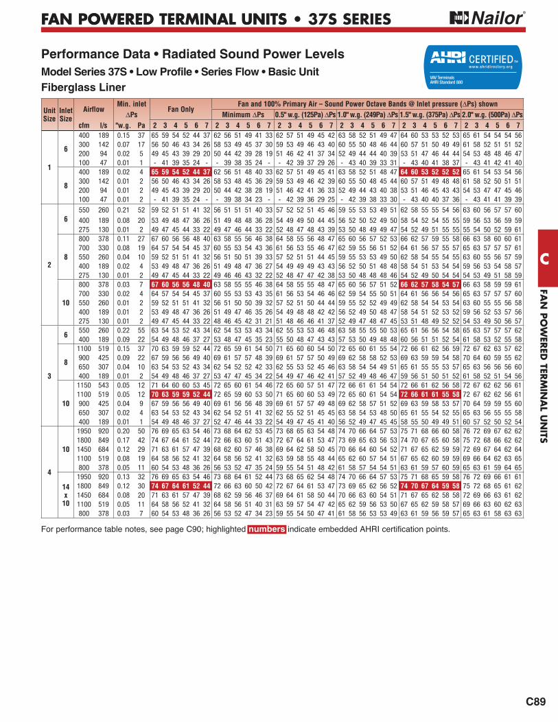
Performance Data • Radiated Sound Power LevelsModel Series 37S • Low Profile • Series Flow • Basic UnitFiberglass Liner
For performance table notes, see page C90; highlighted numbers indicate embedded AHRI certification points.
UnitSize
Inlet Size
AirflowMin. inlet
Fan OnlyFan and 100% Primary Air – Sound Power Octave Bands @ Inlet pressure ( Ps) shown
Ps Minimum Ps 0.5" w.g. (125Pa) Ps 1.0" w.g. (249Pa) Ps 1.5" w.g. (375Pa) Ps 2.0" w.g. (500Pa) Pscfm l/s "w.g. Pa 2 3 4 5 6 7 2 3 4 5 6 7 2 3 4 5 6 7 2 3 4 5 6 7 2 3 4 5 6 7 2 3 4 5 6 7
1
6
400 189 0.15 37 65 59 54 52 44 37 62 56 51 49 41 33 62 57 51 49 45 42 63 58 52 51 49 47 64 60 53 53 52 53 65 61 54 54 54 56300 142 0.07 17 56 50 46 43 34 26 58 53 49 45 37 30 59 53 49 46 43 40 60 55 50 48 46 44 60 57 51 50 49 49 61 58 52 51 51 52200 94 0.02 5 49 45 43 39 29 20 50 44 42 39 28 19 51 46 42 41 37 34 52 49 44 44 40 39 53 51 47 46 44 44 54 53 48 48 46 47100 47 0.01 1 - 41 39 35 24 - - 39 38 35 24 - - 42 39 37 29 26 - 43 40 39 33 31 - 43 40 41 38 37 - 43 41 42 41 40
8
400 189 0.02 4 65 59 54 52 44 37 62 56 51 48 40 33 62 57 51 49 45 41 63 58 52 51 48 47 64 60 53 52 52 52 65 61 54 53 54 56300 142 0.01 2 56 50 46 43 34 26 58 53 48 45 36 29 59 53 49 46 42 39 60 55 50 48 45 44 60 57 51 49 48 48 61 58 52 50 51 51200 94 0.01 2 49 45 43 39 29 20 50 44 42 38 28 19 51 46 42 41 36 33 52 49 44 43 40 38 53 51 46 45 43 43 54 53 47 47 45 46100 47 0.01 2 - 41 39 35 24 - - 39 38 34 23 - - 42 39 36 29 25 - 42 39 38 33 30 - 43 40 40 37 36 - 43 41 41 39 39
2
6550 260 0.21 52 59 52 51 51 41 32 56 51 51 51 40 33 57 52 52 51 45 46 59 55 53 53 49 51 62 58 55 55 54 56 63 60 56 57 57 60
400 189 0.08 20 53 49 48 47 36 26 51 49 48 48 36 28 54 49 49 50 44 45 56 52 50 52 49 50 58 54 52 54 55 55 59 56 53 56 59 59275 130 0.01 2 49 47 45 44 33 22 49 47 46 44 33 22 52 48 47 48 43 39 53 50 48 49 49 47 54 52 49 51 55 55 55 54 50 52 59 61
8
800 378 0.11 27 67 60 56 56 48 40 63 58 55 56 46 38 64 58 55 56 48 47 65 60 56 57 52 53 66 62 57 59 55 58 66 63 58 60 60 61700 330 0.08 19 64 57 54 54 45 37 60 55 53 54 43 36 61 56 53 55 46 47 62 59 55 56 51 52 64 61 56 57 55 57 65 63 57 57 57 61550 260 0.04 10 59 52 51 51 41 32 56 51 50 51 39 33 57 52 51 51 44 45 59 55 53 53 49 50 62 58 54 55 54 55 63 60 55 56 57 59400 189 0.02 4 53 49 48 47 36 26 51 49 48 47 36 27 54 49 49 49 43 43 56 52 50 51 48 48 58 54 51 53 54 54 59 56 53 54 58 57275 130 0.01 2 49 47 45 44 33 22 49 46 46 43 32 22 52 48 47 47 42 38 53 50 48 48 48 46 54 52 49 50 54 54 54 53 49 51 58 59
10
800 378 0.03 7 67 60 56 56 48 40 63 58 55 55 46 38 64 58 55 55 48 47 65 60 56 57 51 52 66 62 57 58 54 57 66 63 58 59 59 61700 330 0.02 4 64 57 54 54 45 37 60 55 53 53 43 35 61 56 53 54 46 46 62 59 54 55 50 51 64 61 56 56 54 56 65 63 57 57 57 60550 260 0.01 2 59 52 51 51 41 32 56 51 50 50 39 32 57 52 51 50 44 44 59 55 52 52 49 49 62 58 54 54 53 54 63 60 55 55 56 58400 189 0.01 2 53 49 48 47 36 26 51 49 47 46 35 26 54 49 48 48 42 42 56 52 49 50 48 47 58 54 51 52 53 52 59 56 52 53 57 56275 130 0.01 2 49 47 45 44 33 22 48 46 45 42 31 21 51 48 46 46 41 37 52 49 47 48 47 45 53 51 48 49 52 52 54 53 49 50 56 57
3
6550 260 0.22 55 63 54 53 52 43 34 62 54 53 53 43 34 62 55 53 53 46 48 63 58 55 55 50 53 65 61 56 56 54 58 65 63 57 57 57 62400 189 0.09 22 54 49 48 46 37 27 53 48 47 45 35 23 55 50 48 47 43 43 57 53 50 49 48 48 60 56 51 51 52 54 61 58 53 52 55 58
8
1100 519 0.15 37 70 63 59 59 52 44 72 65 59 61 54 50 71 65 60 60 54 50 72 65 60 61 55 54 72 66 61 62 56 59 72 67 62 63 57 62900 425 0.09 22 67 59 56 56 49 40 69 61 57 57 48 39 69 61 57 57 50 49 69 62 58 58 52 53 69 63 59 59 54 58 70 64 60 59 55 62650 307 0.04 10 63 54 53 52 43 34 62 54 52 52 42 33 62 55 53 52 45 46 63 58 54 54 49 51 65 61 55 55 53 57 65 63 56 56 56 60400 189 0.01 2 54 49 48 46 37 27 53 47 47 45 34 22 54 49 47 46 42 41 57 52 49 48 46 47 59 56 51 50 51 52 61 58 52 51 54 56
10
1150 543 0.05 12 71 64 60 60 53 45 72 65 60 61 54 46 72 65 60 57 51 47 72 66 61 61 54 54 72 66 61 62 56 58 72 67 62 62 56 611100 519 0.05 12 70 63 59 59 52 44 72 65 59 60 53 50 71 65 60 60 53 49 72 65 60 61 54 54 72 66 61 61 55 58 72 67 62 62 56 61900 425 0.04 9 67 59 56 56 49 40 69 61 56 56 48 39 69 61 57 57 49 48 69 62 58 57 51 52 69 63 59 58 53 57 70 64 59 59 55 60650 307 0.02 4 63 54 53 52 43 34 62 54 52 51 41 32 62 55 52 51 45 45 63 58 54 53 48 50 65 61 55 54 52 55 65 63 56 55 55 58400 189 0.01 1 54 49 48 46 37 27 52 47 46 44 33 22 54 49 47 45 41 40 56 52 49 47 45 45 58 55 50 49 49 51 60 57 52 50 52 54
4
10
1950 920 0.20 50 76 69 65 63 54 46 73 68 64 62 53 45 73 68 65 63 54 48 74 70 66 64 57 53 75 71 68 66 60 58 76 72 69 67 62 621800 849 0.17 42 74 67 64 61 52 44 72 66 63 60 51 43 72 67 64 61 53 47 73 69 65 63 56 53 74 70 67 65 60 58 75 72 68 66 62 621450 684 0.12 29 71 63 61 57 47 39 68 62 60 57 46 38 69 64 62 58 50 45 70 66 64 60 54 52 71 67 65 62 59 59 72 69 67 64 62 641100 519 0.08 19 64 58 56 52 41 32 64 58 56 52 41 32 63 59 58 55 48 44 65 62 60 57 54 51 67 65 62 60 59 59 69 66 64 62 63 65800 378 0.05 11 60 54 53 48 36 26 56 53 52 47 35 24 59 55 54 51 48 42 61 58 57 54 54 51 63 61 59 57 60 59 65 63 61 59 64 65
14x
10
1950 920 0.13 32 76 69 65 63 54 46 73 68 64 61 52 44 73 68 65 62 54 48 74 70 66 64 57 53 75 71 68 65 59 58 76 72 69 66 61 611800 849 0.12 30 74 67 64 61 52 44 72 66 63 60 50 42 72 67 64 61 53 47 73 69 65 62 56 52 74 70 67 64 59 58 75 72 68 65 61 621450 684 0.08 20 71 63 61 57 47 39 68 62 59 56 46 37 69 64 61 58 50 44 70 66 63 60 54 51 71 67 65 62 58 58 72 69 66 63 61 621100 519 0.05 11 64 58 56 52 41 32 64 58 56 51 40 31 63 59 57 54 47 42 65 62 59 56 53 50 67 65 62 59 58 57 69 66 63 60 62 63800 378 0.03 7 60 54 53 48 36 26 56 53 52 47 34 23 59 55 54 50 47 41 61 58 56 53 53 49 63 61 59 56 59 57 65 63 61 58 63 63

FAN
PO
WER
ED T
ERM
INA
L U
NIT
S
C
FAN POWERED TERMINAL UNITS •
C90
FAN POWERED TERMINAL UNITS • 37S SERIES
Motor = ECM.* Primary air valve is closed and therefore primary cfm is zero.
Performance Data • AHRI Certification and Performance NotesModel Series 37S • Low Profile • Series Flow • Basic Unit • AHRI Certification Rating Points
Fiberglass Liner
accordance with AHRI Standards.
Performance Notes for Sound Power Levels:1. Discharge (external) static pressure is 0.25" w.g. (63 Pa) in
all cases, which is the difference ( Ps) in static pressure from terminal discharge to the room.
Discharge Sound Power Levels (SWL) now include duct end reflection energy as part of the standard rating. Including the duct end correction provides sound power levels that would normally be transmitted into an acoustically, non-reflective duct. The effect of including the energy correction to the discharge SWL, is higher sound power levels when compared to previous AHRI certified data. For more information on duct end reflection calculations see AHRI Standard 880.
2. Radiated sound power is the breakout noise transmitted through the unit casing walls.3. Sound power levels are in decibels, dB re 10-12 watts.
4. All sound data listed by octave bands is raw data without any corrections for room absorption or duct attenuation. Dash (-) in space indicates sound power level is less than 20 dB or equal to background.
5. Min. inlet Ps is the minimum operating pressure of the primary air valve section.
6. Asterisk (*) in space indicates that the minimum inlet static pressure requirement is greater than 0.5" w.g. (125 Pa) at rated airflow.
7. Data derived from independent tests conducted in accordance with ANSI / ASHRAE Standard 130 and AHRI Standard 880.
Unit Size
InletSize
Fan Airflow FanWatts
Fan Only* @ .25" w.g. (62 Pa) Ps Primary Airflow
Min. Inlet Fan + 100% Primary @ 1.5" w.g. (375 Pa)Ps w/ .25" w.g. (62 Pa) Discharge Ps
Discharge Radiated Ps Radiatedcfm l/s 2 3 4 5 6 7 2 3 4 5 6 7 cfm l/s "w.g. Pa 2 3 4 5 6 7
1 8 400 189 140 73 68 63 60 57 54 65 59 54 52 44 37 400 189 0.02 4 64 60 53 52 52 522 10 800 378 170 71 69 66 63 60 58 67 60 56 56 48 40 800 378 0.03 7 66 62 57 58 54 573 10 1100 519 400 78 75 70 70 68 65 70 63 59 59 52 44 1100 519 0.05 12 72 66 61 61 55 584 14 x 10 1800 849 600 77 73 72 72 70 67 74 67 64 61 52 44 1800 849 0.12 30 74 70 67 64 59 58

FAN
PO
WER
ED TER
MIN
AL U
NITS
FAN POWERED TERMINAL UNITS •
C
C91
FAN POWERED TERMINAL UNITS • 37SST SERIES
SERIES FLOWCONSTANT ORVARIABLE VOLUME
37SST "STEALTHTM" SERIES
• LOW PROFILE• QUIET OPERATION
Models:
37SST No Heat
37SEST Electric Heat
37SWST Hot Water Heat
STANDARD FEATURES:
• 20 ga. (1.0) galvanized steel construction.
• 16 ga. (1.61) galvanized steel inclined opposed blade primary air damper. 45O
rotation, CW to close. 1/2" (13) dia. plated steel drive shaft. An indicator mark on the end of the shaft shows damper-position. Leakage is less than
• "StealthTM" design technology
radiated sound levels.
discharge optimizes mixing with induced air for rapid and effective
also converts low frequency primary air valve generated sound into more readily attenuated higher frequencies.
control.
• Multi-point averaging Diamond Flow sensor.
either way up, providing the additional
• Access panels are full size on top and bottom of terminal for ease of maintenance and service.
thermal overload protection.
• Motor blower assembly mounted
on special 16 ga. (1.61) angles and isolated from casing with rubber isolators.
• Adjustable PSC solid state fan speed controller with minimum voltage stop.
• Hinged door on fan controls enclosure.
• 1/2" (13), dual density insulation. Exposed edges coated to prevent air erosion. Meets requirements of NFPA 90A and UL 181.
• Available with electric or hot water supplementary heat.
• All controls are mounted on exterior of terminal providing ready access for
• Each terminal factory tested prior to shipment.
• Single point electrical and/or pneumatic main air connection.
• Discharge opening designed for
• Full primary air valve low voltage NEMA 1 type enclosure for factory mounted DDC and analog electronic controls.
Controls:• Nailor EZvav
• Analog electronic and pneumatic controls. Factory supplied, mounted and calibrated.
• Digital controls. Factory mounting and wiring of DDC controls supplied by BMS Controls Contractor.
Options:• ECM/EPIC Fan Technology®.
• Primary air valve controls enclosure
disposable type.
• Toggle disconnect switch (except units with electric heat, when disconnect is an electric heat option and includes fan).
• Various IAQ linings are available.
shutdown (pneumatic controls).
(analog electronic controls).
• Night setback fan/heat cycle (pneumatic and analog).
• Fan unit fusing.
• Hanger brackets.
• FN2 90° Line Voltage controls enclosure on model 37SST and 37SWST (standard on 37SEST).
• FN3 Remote Line Voltage control enclosure.
The 37SST "StealthTM"applications, which are common where zoning requirements limit building height and the architect wishes to maximize the
TM" design technology, this terminal has industry leading low sound levels.
Model 37SWSTModel 37SWST
Inclined opposed bladedamper configurationminimizes noisy turbulenceand provides smooth,accurate, near linearflow control.

FAN
PO
WER
ED T
ERM
INA
L U
NIT
S
C
FAN POWERED TERMINAL UNITS •
C92
FAN POWERED TERMINAL UNITS • 37SST SERIES
DimensionsModel Series 37SST "StealthTM" • Low Profile • Unit Sizes 1 – 3
Dimensional Data
Unit Size
Inlet Size
W W2 LInduced Air
Inlet IW x IH
OutletDischargeDW x DH
FilterSize
1 4, 5, 6, 8 (102, 127, 152, 203)
19 (483)
28 (711)
36 (914)
9 x 11 (229 x 279)
10 3/8 x 6 7/8 (264 x 175)
9 x 11 (229 x 279)
2 6, 8, 10 (152, 203, 254)
26 1/2 (673)
35 1/2 (902)
40 1/4 (1022)
12 x 11 (305 x 279)
11 3/8 x 6 7/8 (289 x 175)
12 x 11 (305 x 279)
3 6, 8, 10 (152, 203, 254)
26 1/2 (673)
35 1/2 (902)
40 1/4 (1022)
12 x 11 (305 x 279)
12 3/8 x 6 7/8 (314 x 175)
12 x 11 (305 x 279)
INDUCED
OPTIONALINDUCEDAIR FILTER
AIRFLOW
OPTIONALPRIMARY AIR VALVE
CONTROLSENCLOSURE
HINGED FANCONTROLSENCLOSURE
DIA. =NOM. – 1/8" (3)
DRIVESHAFT
MULTI-POINTFLOW SENSOR
PRIMARY
AIR
FAN
DW
DH2"
(51)
W
W2
L
5 4/5" (147)
5"(127)
11"(279)
6 1/4"(159)
8"(203)
5 1/2"(140)
2"(51)
IW
IH
6 3/4"(171)
OPTIONAL90° FN2 HINGEDFAN CONTROLS
ENCLOSURE
15"(381)10" (254)14" (356)

FAN
PO
WER
ED TER
MIN
AL U
NITS
FAN POWERED TERMINAL UNITS •
C
C93
FAN POWERED TERMINAL UNITS • 37SST SERIES
OPTIONAL INDUCED AIR FILTER
MULTI-POINTAIRFLOWSENSOR
W2
49 3/4" (1264)
L
5 3/4" (146)
5 1/2" (140)
33 1/2"(851)
W
DH
IW
IH
11"(279)
NOM. – 1/8" (3)
P
PRIMARY
AIR
PRIMARY
AIR
11" (279)
INDUCED
AIR
14" (356) 10" (254)
13 1/4" (337)
41 1/2"(114)
83" (2108)
19 1/2" (495)
INDUCED
AIR
H2
FAN
FAN
OPTIONALPRIMARY AIR
VALVE CONTROLSENCLOSURE
HINGED FANCONTROLSENCLOSURE
11 1/4"(286)
11 1/4"(286)
B
DW
OPTIONAL90° FN2
HINGED FANCONTROLSENCLOSURE
6 3/4"(171)
15" (381)
DimensionsModel Series 37SST "StealthTM" • Low Profile • Unit Size 4
Dimensional Data
Unit Size
Inlet Size
W L B PInduced Air
Inlet IW x IH
OutletDischargeDW x DH
FilterSize
4 10 (254) Round 14 x 10 (356 x 254) Rect.
44 (1118)
36 1/2 (927)
9 3/4 (248)
2 1/16 (52)
12 x 9 (305 x 229)
Qty. of 2
24 1/2 x 6 7/8 (622 x 175)
14 x 10 (356 x 254)
Qty. of 2

FAN
PO
WER
ED T
ERM
INA
L U
NIT
S
C
C94
FAN POWERED TERMINAL UNITS • 37SST SERIES
12" (305)
COILCONNECTION
1 3/4"(44)
3 5/8" (92) D
IW
W3
C E
1 1/8" (29)
11" (279)6 3/4"(171)
FANHOT
WATERCOIL
OPTIONAL90° FN2
HIGNED FANCONTROLSENCLOSURE
15"(381)
Unit Size
Outlet Duct SizeC x D
IW W3 E
1 14 5/8 x 8 3/4 (371 x 222) 9 (229) 29 (737) 20 (508)
2, 3 24 x 9 (610 x 229) 12 (305) 41 3/8 (1051) 29 3/8 (746)
4 41 x 9 (1041 x 229) — — 46 3/8 (1178)
Hot Water Coil Section
Model 37SWSTAvailable in one, two or three row. Coil section installed on unit discharge. Right hand coil connection looking in
(terminals are inverted). Connections must be selected same hand as controls enclosure location.
Standard Features:
• Coil section installed on unit discharge.
• Coil (and header on multi-circuit units) is installed in insulated casing for increased thermal
• 1/2" (13) copper tubes.
• Sweat Connections:All size: 1 Row 1/2" (13), 2 and 3 Row 7/8" (22); O.D. male solder.
• Top and bottom access panels for inspection and coil cleaning.
• Flanged outlet duct connection.
DimensionsModel Series 37SST "StealthTM" • Low Profile • Series Flow
Unit Sizes 1 — 3
Unit Size 4 with FN2 Option
12" (305)
1 3/4"(44)
1" (25)D3 5/8" (92)
FAN
FAN
C
COIL CONNECTION
E
11" (279)6 3/4"(171)
15" (381)
J
90° FN2HINGED FANCONTROLSENCLOSURE
15"(381)OPTIONAL
12" (305)
1 3/4"(44)
1" (25)D
FAN
FAN
C E
J
11" (279)
3 5/8"(92)
COILCONNECTION
HOTWATERCOIL
Unit Size 4
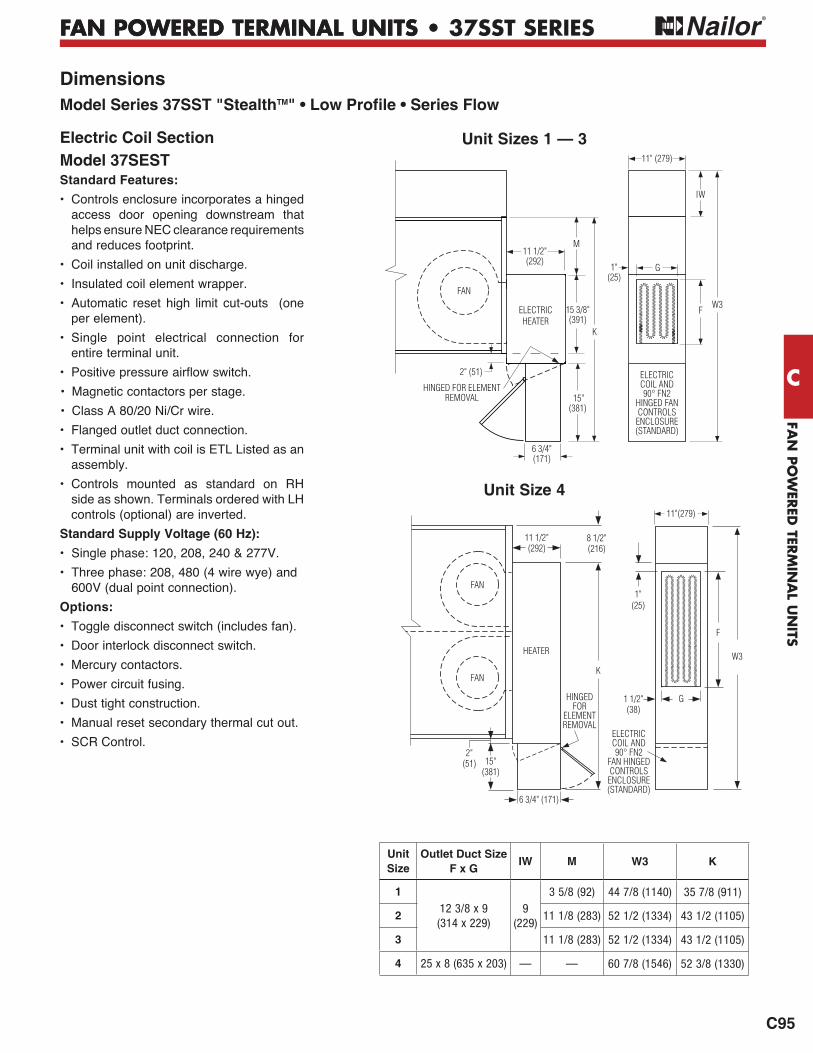
FAN
PO
WER
ED TER
MIN
AL U
NITS
FAN POWERED TERMINAL UNITS •
C
C95
FAN POWERED TERMINAL UNITS • 37SST SERIES
Electric Coil SectionModel 37SEST Standard Features:
• Controls enclosure incorporates a hinged access door opening downstream that helps ensure NEC clearance requirements and reduces footprint.
• Coil installed on unit discharge.
• Insulated coil element wrapper.
• Automatic reset high limit cut-outs (one per element).
• Single point electrical connection for entire terminal unit.
• Magnetic contactors per stage.
• Class A 80/20 Ni/Cr wire.
• Flanged outlet duct connection.
• Terminal unit with coil is ETL Listed as an assembly.
• Controls mounted as standard on RH side as shown. Terminals ordered with LH controls (optional) are inverted.
Standard Supply Voltage (60 Hz):
• Single phase: 120, 208, 240 & 277V.
• Three phase: 208, 480 (4 wire wye) and 600V (dual point connection).
Options:
• Toggle disconnect switch (includes fan).
• Door interlock disconnect switch.
• Mercury contactors.
• Power circuit fusing.
• Dust tight construction.
• Manual reset secondary thermal cut out.
• SCR Control.
DimensionsModel Series 37SST "StealthTM" • Low Profile • Series Flow
Unit Sizes 1 — 3
Unit Size 4
FAN
F
G1"(25)
K
W3
15"(381)
IW
6 3/4"(171)
11" (279)
11 1/2"(292)
HINGED FOR ELEMENTREMOVAL
2" (51) ELECTRICCOIL AND90° FN2
HINGED FAN CONTROLS ENCLOSURE(STANDARD)
15 3/8"(391)
M
ELECTRICHEATER
HEATER
15"(381)
1 1/2"(38)
8 1/2"(216)
G
F
1"(25)
W3
11 1/2" (292)
FAN
FANK
6 3/4" (171)
HINGEDFOR
ELEMENTREMOVAL
11"(279)
2"(51)
ELECTRICCOIL AND90° FN2
FAN HINGED CONTROLS ENCLOSURE(STANDARD)
Unit Size
Outlet Duct SizeF x G
IW M W3 K
1
12 3/8 x 9(314 x 229)
9(229)
3 5/8 (92) 44 7/8 (1140) 35 7/8 (911)
2 11 1/8 (283) 52 1/2 (1334) 43 1/2 (1105)
3 11 1/8 (283) 52 1/2 (1334) 43 1/2 (1105)
4 25 x 8 (635 x 203) — — 60 7/8 (1546) 52 3/8 (1330)
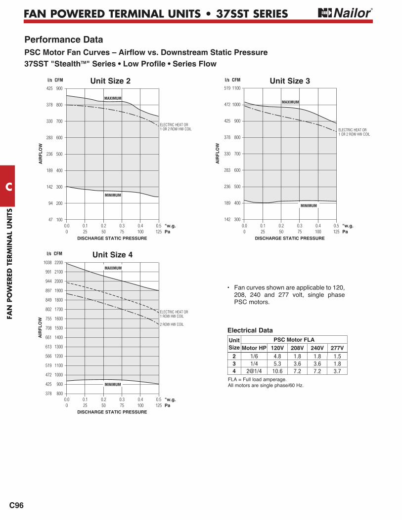
FAN
PO
WER
ED T
ERM
INA
L U
NIT
S
C
C96
FAN POWERED TERMINAL UNITS • 37SST SERIES
Performance DataPSC Motor Fan Curves – Airflow vs. Downstream Static Pressure37SST "StealthTM" Series • Low Profile • Series Flow
Unit Size 2
AIR
FL
OW
900
800
700
600
500
400
300
200
100
MAXIMUM
MINIMUM
425
378
330
283
236
189
142
94
47
l/s CFM
Unit Size 42200
2100
2000
1900
1800
1700
1600
1500
1400
1300
1200
1100
1000
900
800
AIR
FL
OW
MAXIMUM
l/s CFM
1038
991
944
897
849
802
755
708
661
613
566
519
472
425
378
MINIMUM
• Fan curves shown are applicable to 120, 208, 240 and 277 volt, single phase PSC motors.
ELECTRIC HEAT OR1 OR 2 ROW HW COIL
ELECTRIC HEAT OR1 ROW HW COIL
2 ROW HW COIL
Electrical Data
FLA = Full load amperage.All motors are single phase/60 Hz.
0.0 0.1 0.2 0.3 0.4 0.5 "w.g. 0 25 50 75 100 125 Pa DISCHARGE STATIC PRESSURE
0.0 0.1 0.2 0.3 0.4 0.5 "w.g. 0 25 50 75 100 125 Pa DISCHARGE STATIC PRESSURE
Unit Size 31100
1000
900
800
700
600
500
400
300A
IRF
LO
W
MINIMUM
MAXIMUM
l/s CFM
519
472
425
378
330
283
236
189
142 0.0 0.1 0.2 0.3 0.4 0.5 "w.g. 0 25 50 75 100 125 Pa DISCHARGE STATIC PRESSURE
ELECTRIC HEAT OR1 OR 2 ROW HW COIL
Unit Size
PSC Motor FLAMotor HP 120V 208V 240V 277V
2 1/6 4.8 1.8 1.8 1.53 1/4 5.3 3.6 3.6 1.84 2@1/4 10.6 7.2 7.2 3.7
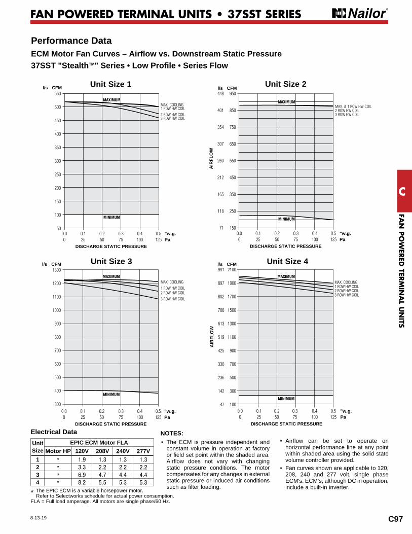
FAN
PO
WER
ED TER
MIN
AL U
NITS
C
C97
FAN POWERED TERMINAL UNITS • 37SST SERIES
Performance DataECM Motor Fan Curves – Airflow vs. Downstream Static Pressure37SST "StealthTM" Series • Low Profile • Series Flow
8-13-19
Unit Size
EPIC ECM Motor FLAMotor HP 120V 208V 240V 277V
1 * 1.9 1.3 1.3 1.32 * 3.3 2.2 2.2 2.23 * 6.9 4.7 4.4 4.44 * 8.2 5.5 5.3 5.3
NOTES:• The ECM is pressure independent and
constant volume in operation at factory or field set point within the shaded area. Airflow does not vary with changing static pressure conditions. The motor compensates for any changes in external static pressure or induced air conditions such as filter loading.
• Airflow can be set to operate on horizontal performance line at any point within shaded area using the solid state volume controller provided.
• Fan curves shown are applicable to 120, 208, 240 and 277 volt, single phase ECM's. ECM's, although DC in operation, include a built-in inverter.
Electrical Data
* The EPIC ECM is a variable horsepower motor. Refer to Selectworks schedule for actual power consumption.
FLA = Full load amperage. All motors are single phase/60 Hz.
Unit Size 42100
1900
1700
1500
1300
1100
900
700
500
300
100
MAXIMUM
MINIMUM
991
897
802
708
613
519
425
330
236
142
47
AIR
FLO
W
l/s CFM
0.0 0.1 0.2 0.3 0.4 0.5 "w.g. 0 25 50 75 100 125 Pa DISCHARGE STATIC PRESSURE
Unit Size 1 550
500
450
400
350
300
250
200
150
100
50
MAXIMUM
l/s CFM
0.0 0.1 0.2 0.3 0.4 0.5 "w.g. 0 25 50 75 100 125 Pa
DISCHARGE STATIC PRESSURE
MINIMUM
Unit Size 2 950
850
750
650
550
450
350
250
150
AIR
FLO
W
MAXIMUM
l/s CFM448
401
354
307
260
212
165
118
71 0.0 0.1 0.2 0.3 0.4 0.5 "w.g. 0 25 50 75 100 125 Pa DISCHARGE STATIC PRESSURE
MINIMUM
Unit Size 3 1300
1200
1100
1000
900
800
700
600
500
400
300
l/s CFM
0.0 0.1 0.2 0.3 0.4 0.5 "w.g. 0 25 50 75 100 125 Pa DISCHARGE STATIC PRESSURE
MAXIMUM
MINIMUM
MAX. COOLING1 ROW HW COIL2 ROW HW COIL3 ROW HW COIL
MAX. COOLING1 ROW HW COIL2 ROW HW COIL3 ROW HW COIL
MAX. COOLING1 ROW HW COIL2 ROW HW COIL3 ROW HW COIL
MAX. & 1 ROW HW COIL2 ROW HW COIL3 ROW HW COIL

FAN
PO
WER
ED T
ERM
INA
L U
NIT
S
C
C98
FAN POWERED TERMINAL UNITS • 37SST SERIES
Performance Data • NC Level Application GuideModel Series 37SST "StealthTM" • Low Profile • Series FlowFiberglass Liner
1. NC Levels are calculated based on procedures as outlined on page C132.2. Dash (-) in space indicates a NC less than 20.
Performance Notes:
UnitSize
Inlet Size
Airflow Min. inletPs
NC Levels @ Inlet Pressure ( Ps) shown
DISCHARGE RADIATED
cfm l/s "w.g. Pa FanOnly
Min. Ps
0.5" w.g. (125 Pa)
1.0" w.g. (250 Pa)
1.5" w.g. (375 Pa)
2.0" w.g. (500 Pa)
FanOnly
Min. Ps
0.5" w.g. (125 Pa)
1.0" w.g. (250 Pa)
1.5" w.g. (375 Pa)
2.0" w.g. (500 Pa)
1
6
400 189 0.15 37 26 24 25 25 25 25 28 25 25 28 29 30300 142 0.07 17 21 - 20 21 21 21 - 20 21 23 25 26200 94 0.02 5 24 20 21 21 24 24 - - - - - -100 47 0.01 1 - - - - 21 20 - - - - - -
8
400 189 0.02 4 26 23 24 25 24 24 28 25 25 28 29 30300 142 0.01 2 21 - - 20 20 21 - 20 21 23 25 26200 94 0.01 2 24 - - 20 21 21 - - - - - -100 47 0.01 2 - - - - - - - - - - - -
2
6550 260 0.21 52 20 - 20 - 20 20 22 22 23 24 26 29400 189 0.08 20 - - - - - 20 - - 20 22 24 28275 130 0.01 2 - - 20 - 20 23 - - - - 24 28
8
800 378 0.11 27 28 24 21 21 23 23 29 28 26 29 31 34700 330 0.08 19 25 23 20 21 21 23 26 25 26 28 30 33550 260 0.04 10 20 - - - - - 22 21 22 24 26 29400 189 0.02 4 - - - - - - - - - 21 23 26275 130 0.01 2 - - - - - 20 - - - - 23 27
10
800 378 0.03 7 28 24 20 20 21 21 29 28 26 29 31 34700 330 0.02 4 25 21 - 20 21 21 26 24 25 28 30 33550 260 0.01 2 20 - - - - - 22 21 22 24 26 29400 189 0.01 2 - - - - - - - - - 21 23 25275 130 0.01 2 - - - - - - - - - - 21 25
3
6550 260 0.22 55 21 25 26 28 29 30 24 23 23 24 28 30400 189 0.09 22 - - - - 20 21 - - - - 23 25
8
1100 519 0.15 37 34 35 34 35 35 35 32 34 34 35 35 35900 425 0.09 22 30 31 31 31 31 33 30 31 31 31 33 33650 307 0.04 10 21 23 24 25 26 28 24 23 23 24 28 30400 189 0.01 2 - - - - - - - - - - 21 24
10
1150 543 0.05 12 35 35 34 35 35 35 33 34 34 34 35 361100 519 0.05 12 34 34 33 34 34 35 32 34 34 35 35 35900 425 0.04 9 30 30 30 30 31 31 30 31 31 31 33 33650 307 0.02 4 21 21 21 23 24 25 24 23 23 24 28 30400 189 0.01 1 - - - - - - - - - - 21 24
4
10
1950 920 0.20 50 35 34 35 36 37 38 38 39 39 40 41 431800 849 0.17 42 33 31 33 34 36 37 35 38 38 39 40 411450 684 0.12 29 26 25 28 30 31 33 31 33 34 35 36 381100 519 0.08 19 - - 21 24 26 26 25 28 26 29 31 34800 378 0.05 11 - - - - - 20 20 - 21 25 28 30
14x
10
1950 920 0.13 32 35 33 34 35 36 37 38 39 39 40 41 431800 849 0.12 30 33 30 33 33 35 36 35 38 38 39 40 411450 684 0.08 20 26 25 26 29 30 31 31 33 34 35 36 381100 519 0.05 11 - - - 21 25 25 25 28 26 29 31 34800 378 0.03 7 - - - - - - 20 - 21 24 28 30
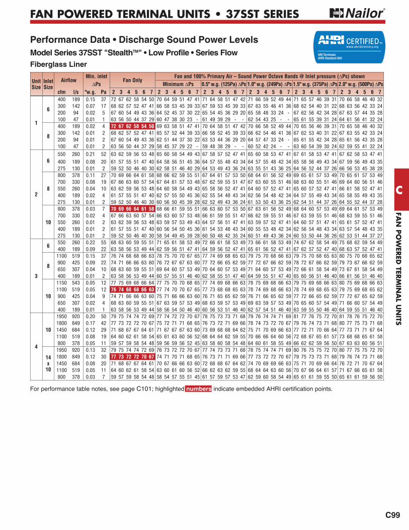
FAN
PO
WER
ED TER
MIN
AL U
NITS
C
C99
FAN POWERED TERMINAL UNITS • 37SST SERIES
Performance Data • Discharge Sound Power LevelsModel Series 37SST "StealthTM" • Low Profile • Series FlowFiberglass Liner
For performance table notes, see page C101; highlighted numbers
UnitSize
Inlet Size
AirflowMin. inlet
Fan OnlyFan and 100% Primary Air – Sound Power Octave Bands @ Inlet pressure ( Ps) shown
Ps Minimum Ps 0.5" w.g. (125Pa) Ps 1.0" w.g. (249Pa) Ps 1.5" w.g. (375Pa) Ps 2.0" w.g. (500Pa) Pscfm l/s "w.g. Pa 2 3 4 5 6 7 2 3 4 5 6 7 2 3 4 5 6 7 2 3 4 5 6 7 2 3 4 5 6 7 2 3 4 5 6 7
1
6
400 189 0.15 37 72 67 62 58 54 50 70 64 59 51 47 41 71 64 58 51 47 42 71 66 59 52 49 44 71 65 57 46 39 31 70 66 58 46 40 32300 142 0.07 17 68 62 57 52 47 41 66 58 53 45 39 33 67 59 53 45 39 33 67 63 55 46 41 36 68 62 54 40 31 22 68 63 56 42 33 24200 94 0.02 5 67 60 54 49 43 36 64 52 45 37 30 22 65 54 45 36 29 20 65 58 48 33 24 - 67 62 56 42 34 28 67 63 57 44 35 28100 47 0.01 1 63 56 50 44 37 29 60 47 38 30 23 - 61 49 39 29 - - 62 54 43 25 - - 65 61 55 39 31 24 64 61 56 41 32 24
8
400 189 0.02 4 72 67 62 58 54 50 69 63 58 51 47 41 70 64 58 51 47 42 70 66 58 52 49 44 70 65 56 46 39 31 70 65 58 46 40 32300 142 0.01 2 68 62 57 52 47 41 65 57 52 44 39 33 66 58 52 45 39 33 66 62 54 46 41 36 67 62 53 40 31 22 67 63 55 42 33 24200 94 0.01 2 67 60 54 49 43 36 62 51 44 37 30 22 63 53 44 36 29 20 64 57 47 33 24 - 65 61 55 42 34 28 65 61 56 43 35 28100 47 0.01 2 63 56 50 44 37 29 58 45 37 29 22 - 59 48 38 29 - - 60 52 42 24 - - 63 60 54 39 30 24 62 59 55 41 32 24
2
6550 260 0.21 52 63 62 59 56 53 48 65 60 58 54 49 43 67 58 57 52 47 41 65 60 58 53 47 41 67 61 58 53 47 41 67 62 58 53 47 41
400 189 0.08 20 61 57 55 51 47 40 64 58 56 51 45 36 64 57 55 48 43 34 64 57 55 48 42 34 65 58 56 49 43 34 67 59 56 49 43 35275 130 0.01 2 59 52 50 46 40 30 62 58 51 46 40 29 64 53 49 43 36 24 63 55 51 43 36 25 64 56 52 44 37 26 66 56 53 45 38 28
8
800 378 0.11 27 70 69 66 64 61 58 68 66 62 59 55 51 67 64 61 57 53 50 68 64 61 56 52 49 69 65 61 57 53 49 70 65 61 57 53 49700 330 0.08 19 67 66 63 60 57 54 67 64 61 57 53 48 67 62 59 55 51 47 67 63 60 55 51 46 68 63 60 55 51 46 69 64 60 56 51 46550 260 0.04 10 63 62 59 56 53 48 64 60 58 54 49 43 65 58 56 52 47 41 64 60 57 52 47 41 65 60 57 52 47 41 66 61 58 52 47 41400 189 0.02 4 61 57 55 51 47 40 62 57 55 50 45 36 62 55 54 48 43 34 62 56 54 48 42 34 64 57 55 49 43 34 65 58 55 49 43 35275 130 0.01 2 59 52 50 46 40 30 60 56 50 45 39 28 62 52 49 43 36 24 61 53 50 43 36 25 62 54 51 44 37 26 64 55 52 44 37 28
10
800 378 0.03 7 70 69 66 64 61 58 68 66 61 59 55 51 66 63 60 57 53 50 67 63 61 56 52 49 68 64 60 57 53 49 69 64 61 57 53 49700 330 0.02 4 67 66 63 60 57 54 66 63 60 57 53 48 66 61 59 55 51 47 66 62 59 55 51 46 67 63 59 55 51 46 68 63 59 55 51 46550 260 0.01 2 63 62 59 56 53 48 63 59 57 53 49 43 64 57 56 51 47 41 63 59 57 52 47 41 64 60 57 51 47 41 65 61 57 52 47 41400 189 0.01 2 61 57 55 51 47 40 60 56 54 50 45 36 61 54 53 48 43 34 60 55 53 48 42 34 62 56 54 48 43 34 63 57 54 48 43 35275 130 0.01 2 59 52 50 46 40 30 58 54 49 45 39 28 60 50 48 42 35 24 60 51 49 43 36 24 60 53 50 44 36 26 62 53 51 44 37 27
3
6550 260 0.22 55 68 63 60 59 55 51 71 65 61 58 53 49 72 66 61 58 53 49 73 66 61 58 53 49 74 67 62 58 54 49 75 68 62 59 54 49400 189 0.09 22 63 58 56 53 49 44 62 59 56 51 47 41 64 59 56 52 47 41 65 61 56 52 47 41 67 62 57 52 47 40 68 63 57 52 47 41
8
1100 519 0.15 37 76 74 68 68 66 63 78 75 70 70 67 65 77 74 69 68 65 63 79 75 70 68 66 63 79 75 70 68 65 63 80 75 70 68 65 62900 425 0.09 22 74 71 66 66 63 60 76 72 67 67 63 60 77 72 66 65 62 59 77 72 67 66 62 59 78 72 67 66 62 59 79 73 67 66 62 59650 307 0.04 10 68 63 60 59 55 51 69 64 60 57 53 49 70 64 60 57 53 49 71 64 60 57 53 49 72 66 61 58 54 49 73 67 61 58 54 49400 189 0.01 2 63 58 56 53 49 44 60 57 55 51 46 40 62 58 55 51 47 40 64 59 55 51 47 40 65 60 56 51 46 40 66 61 56 51 46 40
10
1150 543 0.05 12 77 75 69 68 66 64 77 75 70 70 68 65 77 74 69 68 66 63 78 75 69 68 66 63 79 75 69 68 66 63 80 75 69 68 66 631100 519 0.05 12 76 74 68 68 66 63 77 74 70 70 67 65 77 73 68 68 65 63 78 74 69 68 66 63 78 74 69 68 65 63 79 75 69 68 65 62900 425 0.04 9 74 71 66 66 63 60 75 71 66 66 63 60 76 71 65 65 62 59 76 71 66 65 62 59 77 72 66 65 62 59 77 72 67 65 62 59650 307 0.02 4 68 63 60 59 55 51 67 63 59 57 53 49 68 63 59 57 53 49 69 63 59 57 53 49 70 65 60 57 54 49 71 66 60 57 54 49400 189 0.01 1 63 58 56 53 49 44 58 56 54 50 46 40 60 56 53 51 46 40 62 57 54 51 46 40 63 59 55 50 46 40 64 59 55 51 46 40
4
10
1950 920 0.20 50 79 75 74 74 72 69 77 74 72 72 70 67 78 75 73 73 71 68 79 76 74 74 71 69 81 77 76 75 72 70 81 78 76 75 72 701800 849 0.17 42 77 73 72 72 70 67 75 72 71 71 68 65 76 73 72 71 69 66 78 74 73 72 70 67 79 76 74 73 71 68 80 77 75 73 71 681450 684 0.12 29 71 68 67 67 64 61 71 67 67 67 63 60 73 69 68 68 64 62 75 71 70 69 66 63 77 72 71 70 66 64 77 73 71 71 67 641100 519 0.08 19 64 60 62 61 58 54 65 61 63 60 56 52 68 64 64 62 59 55 70 66 66 64 60 56 72 68 67 65 61 57 73 68 68 65 61 58800 378 0.05 11 59 57 59 58 54 48 59 56 59 56 52 45 63 58 60 58 54 48 64 60 61 58 55 49 66 62 62 59 56 50 67 63 63 60 56 51
14x
10
1950 920 0.13 32 79 75 74 74 72 69 76 73 72 72 70 67 77 74 73 73 71 68 78 75 74 74 71 69 80 76 75 75 72 70 80 77 75 75 72 701800 849 0.12 30 77 73 72 72 70 67 74 71 70 71 68 65 76 73 71 71 69 66 77 73 72 72 70 67 79 75 73 73 71 68 79 76 74 73 71 681450 684 0.08 20 71 68 67 67 64 61 70 67 66 66 63 60 72 68 68 67 64 62 74 70 69 69 66 63 75 71 70 69 66 64 76 72 71 70 67 641100 519 0.05 11 64 60 62 61 58 54 63 60 61 60 56 52 66 62 63 62 59 55 68 64 64 63 60 56 70 67 66 64 61 57 71 67 66 65 61 58800 378 0.03 7 59 57 59 58 54 48 58 54 57 55 51 45 61 57 59 57 53 47 62 59 60 58 54 49 65 61 61 59 55 50 65 61 61 59 56 50
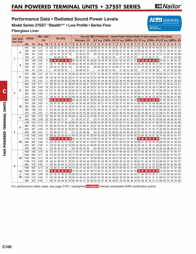
FAN
PO
WER
ED T
ERM
INA
L U
NIT
S
C
C100
FAN POWERED TERMINAL UNITS • 37SST SERIES
Performance Data • Radiated Sound Power LevelsModel Series 37SST "StealthTM" • Low Profile • Series Flow Fiberglass Liner
For performance table notes, see page C101; highlighted numbers
UnitSize
Inlet Size
AirflowMin. inlet
Fan OnlyFan and 100% Primary Air – Sound Power Octave Bands @ Inlet pressure ( Ps) shown
Ps Minimum Ps 0.5" w.g. (125Pa) Ps 1.0" w.g. (249Pa) Ps 1.5" w.g. (375Pa) Ps 2.0" w.g. (500Pa) Pscfm l/s "w.g. Pa 2 3 4 5 6 7 2 3 4 5 6 7 2 3 4 5 6 7 2 3 4 5 6 7 2 3 4 5 6 7 2 3 4 5 6 7
1
6
400 189 0.15 37 63 58 52 47 42 36 60 56 49 44 39 33 60 56 49 45 40 34 61 58 50 46 42 37 62 59 50 46 44 40 63 60 51 47 45 43300 142 0.07 17 55 51 44 38 33 26 56 52 46 41 35 29 58 53 47 41 36 30 58 54 47 42 38 34 58 56 48 43 40 37 59 57 49 43 41 40200 94 0.02 5 50 45 41 34 27 19 - 43 39 33 25 - 49 45 40 34 28 21 50 47 41 36 32 28 51 50 43 38 36 34 51 51 44 40 39 39100 47 0.01 1 - 40 36 30 22 - - 40 36 29 21 - - 41 36 30 23 18 - 41 37 32 27 25 - 42 37 34 31 31 - 42 37 35 34 36
8
400 189 0.02 4 63 58 52 47 42 36 60 56 49 44 39 32 60 56 49 45 39 33 61 58 50 45 41 37 62 59 50 46 43 40 63 60 51 46 45 42300 142 0.01 2 55 51 44 38 33 26 56 52 46 40 35 28 58 53 46 41 36 30 58 54 47 42 38 33 58 56 48 42 40 37 59 57 48 43 41 39200 94 0.01 2 50 45 41 34 27 19 - 43 39 32 25 - 49 45 39 34 27 20 50 47 41 35 31 27 51 50 42 37 35 33 51 51 43 39 38 38100 47 0.01 2 - 40 36 30 22 - - 39 36 29 21 - - 41 36 30 23 18 - 41 36 31 26 24 - 41 37 33 30 30 - 42 37 34 33 35
2
6550 260 0.21 52 57 51 48 43 35 28 56 50 48 43 34 27 57 51 49 45 37 32 60 54 50 48 43 40 62 57 52 51 50 48 64 59 53 53 55 53
400 189 0.08 20 53 48 45 40 32 26 51 47 45 40 30 22 55 48 46 44 38 32 57 51 48 48 45 41 59 54 50 52 52 50 60 56 51 55 57 56275 130 0.01 2 49 45 43 38 30 23 49 45 43 36 28 20 53 47 44 44 42 33 55 49 45 46 48 43 56 51 47 49 54 54 57 52 48 51 58 62
8
800 378 0.11 27 65 58 54 51 42 36 64 56 52 48 41 35 63 56 52 48 42 37 65 59 54 51 46 42 66 61 55 54 51 47 67 63 56 55 53 51700 330 0.08 19 62 55 52 48 39 33 61 54 51 46 38 33 61 54 52 47 40 36 63 57 53 50 45 41 65 60 55 53 49 47 66 62 56 54 53 51550 260 0.04 10 57 51 48 43 35 28 56 50 47 42 33 27 57 51 48 44 36 32 60 54 50 47 43 39 62 57 52 51 49 47 64 59 53 53 54 52400 189 0.02 4 53 48 45 40 32 26 51 47 44 39 30 22 55 48 45 43 38 31 57 51 47 47 44 40 59 54 49 51 51 48 60 56 51 54 56 55275 130 0.01 2 49 45 43 38 30 23 48 44 42 36 27 20 53 46 43 43 41 32 54 48 45 45 47 42 56 51 46 48 53 53 57 52 48 50 57 60
10
800 378 0.03 7 65 58 54 51 42 36 64 56 52 48 41 35 63 56 52 48 42 37 65 59 54 51 46 42 66 61 55 53 50 47 67 63 56 55 53 51700 330 0.02 4 62 55 52 48 39 33 61 54 50 46 38 32 61 54 51 47 40 35 63 57 53 50 45 41 65 60 54 52 49 46 66 62 55 54 52 50550 260 0.01 2 57 51 48 43 35 28 56 50 47 42 33 26 57 51 48 44 36 31 60 54 50 47 43 39 62 57 51 50 49 46 64 59 52 52 54 51400 189 0.01 2 53 48 45 40 32 26 51 47 44 38 29 21 55 48 45 42 37 30 57 51 47 46 44 39 59 54 49 50 50 47 60 56 50 53 55 53275 130 0.01 2 49 45 43 38 30 23 48 44 42 35 26 19 52 46 43 42 40 31 54 48 45 45 46 41 55 50 46 47 51 51 56 51 47 49 55 58
3
6550 260 0.22 55 59 52 50 44 34 26 60 52 49 44 35 27 60 52 49 45 37 33 61 55 50 47 40 38 63 58 52 48 43 43 63 60 53 49 45 46400 189 0.09 22 53 46 43 37 27 - 51 45 43 37 27 - 53 47 43 39 33 27 55 50 45 41 37 33 57 54 47 44 41 39 59 56 49 46 44 43
8
1100 519 0.15 37 67 61 57 57 48 39 68 63 56 52 45 38 69 63 56 52 45 39 70 63 57 54 46 42 70 64 58 55 47 46 70 64 58 55 48 48900 425 0.09 22 64 58 55 53 41 34 67 58 53 49 41 35 67 58 53 49 42 37 67 60 54 50 43 40 68 61 55 51 44 43 68 62 56 52 45 46650 307 0.04 10 59 52 50 44 34 26 60 52 48 43 34 27 60 52 48 44 36 32 61 55 50 46 39 37 63 58 51 47 42 41 63 60 52 48 44 45400 189 0.01 2 53 46 43 37 27 - 51 45 42 36 26 - 53 47 43 38 32 26 55 50 45 40 36 32 57 53 47 43 40 38 58 55 48 45 43 42
10
1150 543 0.05 12 68 62 58 58 50 41 69 62 56 52 45 39 69 63 56 52 45 40 69 63 57 53 46 42 70 64 58 54 47 45 70 65 58 55 47 471100 519 0.05 12 67 61 57 57 48 39 68 63 56 52 44 37 69 63 56 52 45 39 70 63 57 53 46 42 70 64 58 54 47 45 70 64 58 55 48 47900 425 0.04 9 64 58 55 53 41 34 67 58 52 49 41 35 67 58 53 49 41 36 67 60 54 50 42 39 68 61 55 50 43 43 68 62 55 51 44 45650 307 0.02 4 59 52 50 44 34 26 60 52 48 43 33 26 60 52 48 43 35 31 61 55 49 45 38 35 63 58 51 46 41 40 63 60 52 47 43 44400 189 0.01 1 53 46 43 37 27 - 50 44 42 35 25 - 52 46 43 37 31 25 54 49 44 40 35 31 56 53 46 42 39 37 58 55 48 44 41 41
4
10
1950 920 0.20 50 72 64 57 54 49 44 73 65 57 54 48 42 73 65 58 54 49 44 74 66 59 55 52 49 75 68 60 56 54 54 76 68 61 57 56 571800 849 0.17 42 70 62 56 52 47 42 72 63 56 52 46 40 72 63 57 53 48 43 73 65 58 54 51 48 74 67 59 56 53 53 75 68 60 57 55 571450 684 0.12 29 67 58 53 49 43 36 68 59 53 48 41 35 69 60 54 49 44 40 70 62 56 51 48 46 71 64 58 53 52 52 72 65 60 55 55 561100 519 0.08 19 62 54 49 44 37 29 64 54 49 44 36 29 63 55 50 46 43 39 65 58 53 49 47 46 67 61 56 52 52 52 69 63 57 54 55 57800 378 0.05 11 58 50 46 40 32 23 57 49 45 38 30 21 59 52 47 43 42 37 62 55 50 47 47 45 64 58 53 51 52 52 66 60 55 53 56 58
14x
10
1950 920 0.13 32 72 64 57 54 49 44 73 65 57 53 48 41 73 65 58 54 49 44 74 66 59 55 51 48 75 68 60 56 54 53 76 68 61 57 55 561800 849 0.12 30 70 62 56 52 47 42 72 63 56 52 45 39 72 63 57 52 47 43 73 65 58 54 50 48 74 67 59 55 53 53 75 68 60 56 55 561450 684 0.08 20 67 58 53 49 43 36 68 59 53 48 41 34 69 60 54 49 44 40 70 62 56 51 48 45 71 64 58 53 52 51 72 65 59 54 54 551100 519 0.05 11 62 54 49 44 37 29 64 54 49 43 35 28 63 55 50 45 42 38 65 58 52 48 46 44 67 61 55 51 51 51 69 63 57 53 54 55800 378 0.03 7 58 50 46 40 32 23 56 49 44 37 29 20 59 52 47 42 40 36 61 55 50 46 46 43 63 58 53 50 51 51 65 60 55 52 54 56
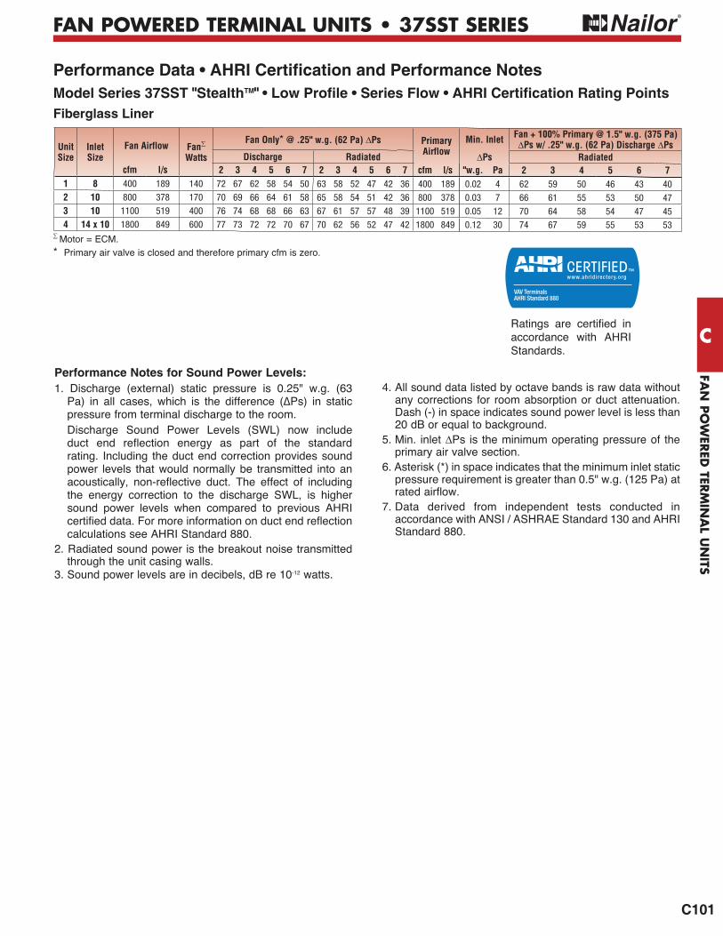
FAN
PO
WER
ED TER
MIN
AL U
NITS
C
C101
FAN POWERED TERMINAL UNITS • 37SST SERIES
Motor = ECM.* Primary air valve is closed and therefore primary cfm is zero.
Performance Data • AHRI Certification and Performance NotesModel Series 37SST "StealthTM" • Low Profile • Series Flow • AHRI Certification Rating PointsFiberglass Liner
accordance with AHRI Standards.
Performance Notes for Sound Power Levels:1. Discharge (external) static pressure is 0.25" w.g. (63
pressure from terminal discharge to the room. Discharge Sound Power Levels (SWL) now include
duct end reflection energy as part of the standard rating. Including the duct end correction provides sound power levels that would normally be transmitted into an acoustically, non-reflective duct. The effect of including the energy correction to the discharge SWL, is higher sound power levels when compared to previous AHRI certified data. For more information on duct end reflection calculations see AHRI Standard 880.
2. Radiated sound power is the breakout noise transmitted through the unit casing walls.
3. Sound power levels are in decibels, dB re 10-12 watts.
4. All sound data listed by octave bands is raw data without any corrections for room absorption or duct attenuation. Dash (-) in space indicates sound power level is less than 20 dB or equal to background.
5. Min. inlet Ps is the minimum operating pressure of the primary air valve section.
6. Asterisk (*) in space indicates that the minimum inlet static pressure requirement is greater than 0.5" w.g. (125 Pa) at rated airflow.
7. Data derived from independent tests conducted in accordance with ANSI / ASHRAE Standard 130 and AHRI Standard 880.
Unit Size
InletSize
Fan Airflow FanWatts
Fan Only* @ .25" w.g. (62 Pa) Ps Primary Airflow
Min. Inlet Fan + 100% Primary @ 1.5" w.g. (375 Pa)Ps w/ .25" w.g. (62 Pa) Discharge Ps
Discharge Radiated Ps Radiatedcfm l/s 2 3 4 5 6 7 2 3 4 5 6 7 cfm l/s "w.g. Pa 2 3 4 5 6 7
1 8 400 189 140 72 67 62 58 54 50 63 58 52 47 42 36 400 189 0.02 4 62 59 50 46 43 402 10 800 378 170 70 69 66 64 61 58 65 58 54 51 42 36 800 378 0.03 7 66 61 55 53 50 473 10 1100 519 400 76 74 68 68 66 63 67 61 57 57 48 39 1100 519 0.05 12 70 64 58 54 47 454 14 x 10 1800 849 600 77 73 72 72 70 67 70 62 56 52 47 42 1800 849 0.12 30 74 67 59 55 53 53
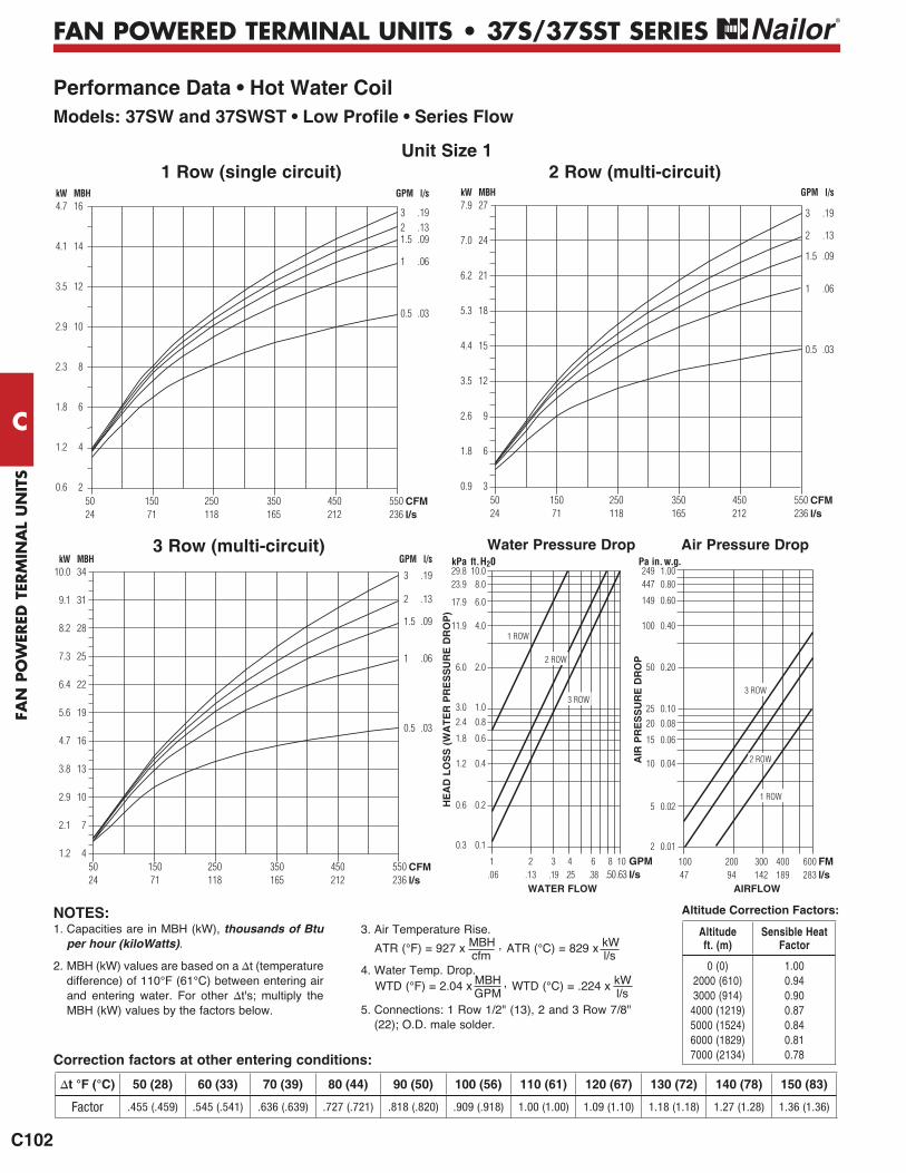
FAN
PO
WER
ED T
ERM
INA
L U
NIT
S
C
C102
FAN POWERED TERMINAL UNITS • 37S/37SST SERIES
Performance Data • Hot Water CoilModels: 37SW and 37SWST • Low Profile • Series Flow
2 Row (multi-circuit)
16
14
12
10
8
6
4
2
4.7
4.1
3.5
2.9
2.3
1.8
1.2
0.6
kW MBH
50 150 250 350 450 550 24 71 118 165 212 236
CFMl/s
GPM l/s
321.5
1
0.5
.19
.13
.09
.06
.03
1 Row (single circuit)
3 Row (multi-circuit)
27
24
21
18
15
12
9
6
3
7.9
7.0
6.2
5.3
4.4
3.5
2.6
1.8
0.9
kW MBH
50 150 250 350 450 550 24 71 118 165 212 236
CFMl/s
GPM l/s
3
2
1.5
1
0.5
.19
.13
.09
.06
.03
34
31
28
25
22
19
16
13
10
7
4
10.0
9.1
8.2
7.3
6.4
5.6
4.7
3.8
2.9
2.1
1.2
kW MBH
50 150 250 350 450 550 24 71 118 165 212 236
CFMl/s
GPM l/s
3
2
1.5
1
0.5
.19
.13
.09
.06
.03
Unit Size 1
1 ROW
2 ROW
3 ROW
1 ROW
2 ROW
3 ROW
WATER FLOW AIRFLOW
1 2 3 4 6 8 10 GPM .06 .13 .19 .25 .38 .50 .63 l/s
100 200 300 400 600 FM 47 94 142 189 283 l/s
Air Pressure DropWater Pressure Drop
HE
AD
LO
SS
(W
AT
ER
PR
ES
SU
RE
DR
OP
)
10.08.0
6.0
4.0
2.0
1.00.8
0.6
0.4
0.2
0.1
kPa ft. H2029.823.9
17.9
11.9
6.0
3.02.4
1.8
1.2
0.6
0.3
AIR
PR
ES
SU
RE
DR
OP
1.000.80
0.60
0.40
0.20
0.100.08
0.06
0.04
0.02
0.01
Pa in. w.g.249447
149
100
50
2520
15
10
5
2
Correction factors at other entering conditions:
1. Capacities are in MBH (kW), thousands of Btu per hour (kiloWatts).
2. MBH (kW) values are based on a t (temperature difference) of 110°F (61°C) between entering air and entering water. For other t's; multiply the MBH (kW) values by the factors below.
3. Air Temperature Rise.
4. Water Temp. Drop.
5. Connections: 1 Row 1/2" (13), 2 and 3 Row 7/8" (22); O.D. male solder.
ATR (°C) = 829 x kW l/s
ATR (°F) = 927 x MBH , cfm
WTD (°C) = .224 x kW l/s
WTD (°F) = 2.04 x MBH , GPM
NOTES:
50 (28) 60 (33) 70 (39) 80 (44) 90 (50) 100 (56) 110 (61) 120 (67) 130 (72) 140 (78) 150 (83)
Factor .455 (.459) .545 (.541) .636 (.639) .727 (.721) .818 (.820) .909 (.918) 1.00 (1.00) 1.09 (1.10) 1.18 (1.18) 1.27 (1.28) 1.36 (1.36)
Altitude Correction Factors:
Altitude ft. (m)
Sensible Heat Factor
0 (0)2000 (610) 3000 (914)
4000 (1219) 5000 (1524) 6000 (1829) 7000 (2134)
1.00 0.94 0.90 0.87 0.84 0.81 0.78
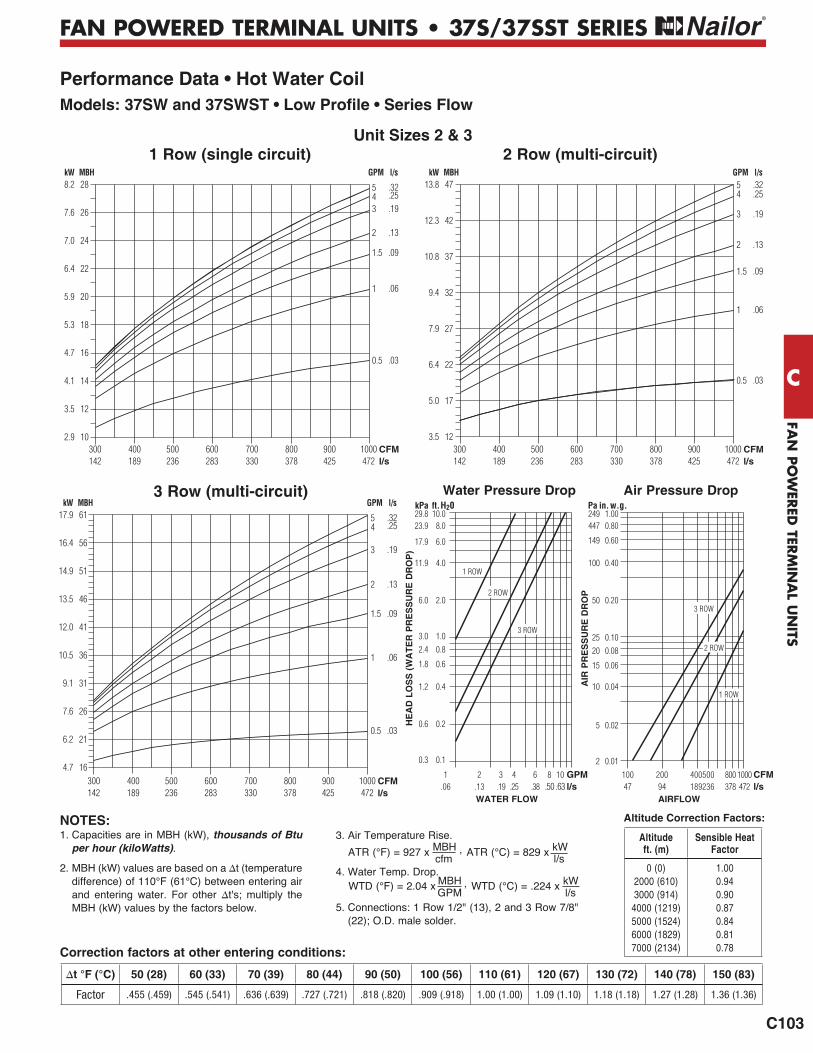
FAN
PO
WER
ED TER
MIN
AL U
NITS
C
C103
FAN POWERED TERMINAL UNITS • 37S/37SST SERIES
Performance Data • Hot Water CoilModels: 37SW and 37SWST • Low Profile • Series Flow
2 Row (multi-circuit)1 Row (single circuit)
3 Row (multi-circuit)
300 400 500 600 700 800 900 1000142 189 236 283 330 378 425 472
CFMl/s
47
42
37
32
27
22
17
12
13.8
12.3
10.8
9.4
7.9
6.4
5.0
3.5
kW MBH GPM l/s54
3
2
1.5
1
0.5
.32
.25
.19
.13
.09
.06
.03
Unit Sizes 2 & 3
1 ROW
2 ROW
3 ROW
1 ROW
2 ROW
3 ROW
300 400 500 600 700 800 900 1000142 189 236 283 330 378 425 472
CFMl/s
28
26
24
22
20
18
16
14
12
10
8.2
7.6
7.0
6.4
5.9
5.3
4.7
4.1
3.5
2.9
kW MBH GPM l/s
543
2
1.5
1
0.5
.32
.25
.19
.13
.09
.06
.03
300 400 500 600 700 800 900 1000142 189 236 283 330 378 425 472
CFMl/s
61
56
51
46
41
36
31
26
21
16
17.9
16.4
14.9
13.5
12.0
10.5
9.1
7.6
6.2
4.7
kW MBH GPM l/s
54
3
2
1.5
1
0.5
.32
.25
.19
.13
.09
.06
.03
Air Pressure DropWater Pressure Drop
WATER FLOW AIRFLOW
HE
AD
LO
SS
(W
AT
ER
PR
ES
SU
RE
DR
OP
)
1 2 3 4 6 8 10 GPM .06 .13 .19 .25 .38 .50 .63 l/s
10.08.0
6.0
4.0
2.0
1.00.8
0.6
0.4
0.2
0.1
kPa ft. H2029.823.9
17.9
11.9
6.0
3.02.4
1.8
1.2
0.6
0.3
100 200 400 500 800 1000 CFM 47 94 189 236 378 472 l/s
AIR
PR
ES
SU
RE
DR
OP
1.000.80
0.60
0.40
0.20
0.100.08
0.06
0.04
0.02
0.01
Pa in. w.g.249447
149
100
50
2520
15
10
5
2
Correction factors at other entering conditions:
1. Capacities are in MBH (kW), thousands of Btu per hour (kiloWatts).
2. MBH (kW) values are based on a t (temperature difference) of 110°F (61°C) between entering air and entering water. For other t's; multiply the MBH (kW) values by the factors below.
3. Air Temperature Rise.
4. Water Temp. Drop.
5. Connections: 1 Row 1/2" (13), 2 and 3 Row 7/8" (22); O.D. male solder.
ATR (°C) = 829 x kW l/s
ATR (°F) = 927 x MBH , cfm
WTD (°C) = .224 x kW l/s
WTD (°F) = 2.04 x MBH , GPM
NOTES:
50 (28) 60 (33) 70 (39) 80 (44) 90 (50) 100 (56) 110 (61) 120 (67) 130 (72) 140 (78) 150 (83)
Factor .455 (.459) .545 (.541) .636 (.639) .727 (.721) .818 (.820) .909 (.918) 1.00 (1.00) 1.09 (1.10) 1.18 (1.18) 1.27 (1.28) 1.36 (1.36)
Altitude Correction Factors:
Altitude ft. (m)
Sensible Heat Factor
0 (0)2000 (610) 3000 (914)
4000 (1219) 5000 (1524) 6000 (1829) 7000 (2134)
1.00 0.94 0.90 0.87 0.84 0.81 0.78

FAN
PO
WER
ED T
ERM
INA
L U
NIT
S
C
C104
FAN POWERED TERMINAL UNITS • 37S/37SST SERIES
Performance Data • Hot Water CoilModels: 37SW and 37SWST • Low Profile • Series Flow
2 Row (multi-circuit)
CFMl/s
800 1000 1200 1400 1600 1800 2000378 472 566 661 755 849 944
51
46
41
36
31
26
21
16
14.9
13.5
12.0
10.5
9.1
7.6
6.2
4.7
kW MBH GPM l/s7.5
54
3
2
1.5
1
0.5
.47
.32
.25
.19
.13
.09
.06
.03
1 Row (single circuit)
3 Row (multi-circuit)
87
82
77
72
67
62
57
52
47
42
37
32
27
22
25.5
24.0
22.6
21.1
19.6
18.2
16.7
15.2
13.8
12.3
10.8
9.4
7.9
6.4
kW MBH GPM l/s7.5
5
4
3
2
1.5
1
0.5
.47
.32
.25
.19
.13
.09
.06
.03
CFMl/s
600 800 1000 1200 1400 1600 1800 283 378 472 566 661 755 849
CFMl/s
800 1000 1200 1400 1600 1800 2000378 472 566 661 755 849 944
120
110
100
90
80
70
60
50
40
30
35.2
32.2
29.3
26.4
23.4
20.5
17.6
14.7
11.7
8.8
kW MBH GPM l/s
10
7.5
5
4
3
2
1.5
1
.63
.47
.32
.25
.19
.13
.09
.06
1 ROW
2 ROW
3 ROW
1 ROW
2 ROW
3 ROW
Unit Size 4
WATER FLOW AIRFLOW
1 2 3 4 6 8 10 GPM .06 .13 .19 .25 .38 .50 .63 l/s
Air Pressure DropWater Pressure Drop
HE
AD
LO
SS
(WA
TER
PR
ES
SU
RE
DR
OP
)
10.08.0
6.0
4.0
2.0
1.00.8
0.6
0.4
0.2
0.1
kPa ft. H2029.823.9
17.9
11.9
6.0
3.02.4
1.8
1.2
0.6
0.3
AIR
PR
ES
SU
RE
DR
OP
1.000.80
0.60
0.40
0.20
0.100.08
0.06
0.04
0.02
0.01
Pa in. w.g.249447
149
100
50
2520
15
10
5
2
Correction factors at other entering conditions:
1. Capacities are in MBH (kW), thousands of Btu per hour (kiloWatts).
2. MBH (kW) values are based on a ∆t (temperature difference) of 110°F (61°C) between entering air and entering water. For other ∆t's; multiply the MBH (kW) values by the factors below.
3. Air Temperature Rise.
4. Water Temp. Drop.
5. Connections: 1 Row 1/2" (13), 2 and 3 Row 7/8" (22); O.D. male solder.
ATR (°C) = 829 x kW l/s
ATR (°F) = 927 x MBH , cfm
WTD (°C) = .224 x kW l/s
WTD (°F) = 2.04 x MBH , GPM
NOTES:
∆t °F (°C) 50 (28) 60 (33) 70 (39) 80 (44) 90 (50) 100 (56) 110 (61) 120 (67) 130 (72) 140 (78) 150 (83)
Factor .455 (.459) .545 (.541) .636 (.639) .727 (.721) .818 (.820) .909 (.918) 1.00 (1.00) 1.09 (1.10) 1.18 (1.18) 1.27 (1.28) 1.36 (1.36)
Altitude Correction Factors:
Altitude ft. (m)
Sensible Heat Factor
0 (0)2000 (610) 3000 (914)
4000 (1219) 5000 (1524) 6000 (1829) 7000 (2134)
1.00 0.94 0.90 0.87 0.84 0.81 0.78
100 200 400 600 1000 2000 CFM 47 94 189 283 472 944 l/s

FAN
PO
WER
ED T
ERM
INA
L U
NIT
S
C
C132
FAN POWERED TERMINAL UNITS
Performance Data ExplanationSound Power Levels vs. NC Levels
The Nailor Model Series: 35S, 35SST, 37S, 37SST, 35N and 37N fan powered terminal unit performance data is presented in two forms.
The laboratory obtained discharge and radiated sound power levels in octave bands 2 through 7 (125 through 4000 Hz) center frequency for each unit size at various flow rates and inlet static pressures is presented. This data is derived in accordance with ANSI/ASHRAE Standard 130 and AHRI Standard 880. This data is raw with no attenuation deductions and includes AHRI Certification standard rating points.
Nailor also provides an "NC Level" table as an application aid in terminal selection, which include attenuation allowances as explained below. The suggested attenuation allowances are typical and are not representative of specific job site conditions. It is recommended that the sound power level data be used and a detailed NC calculation be performed using the procedures outlined in AHRI Standard 885, Appendix E for accurate space sound levels.
Explanation of NC LevelsTabulated NC levels are based on attenuation values as outlined in AHRI Standard 885 Procedure for Estimating Occupied Space Sound Levels in the Application of Air Terminals and Air Outlets". AHRI Standard 885, Appendix E provides typical sound attenuation values for air terminal discharge sound and air terminal radiated sound. As stated in AHRI Standard 885, Appendix E, These values can be used as a quick method of estimating space sound levels when a detailed evaluation is not available. The attenuation values are required for use by manufacturers to catalog application sound levels. In product catalogs, the end user environments are not known and the following factors are provided as typical attenuation values. Use of these values will allow better comparison between manufacturers and give the end user a value which will be expected to be applicable for many types of space.
Radiated SoundTable E1 of Appendix E provides typical radiated sound attenuation values for three types of ceiling: Type 1 – Glass Fiber; Type 2 – Mineral Fiber; Type 3 – Solid Gypsum Board.Since Mineral Fiber tile ceilings are the most common construction used in commercial buildings, these values have been used to tabulate Radiated NC levels.The following table provides the calculation method for the radiated sound total attenuation values based on AHRI Standard 885.
The ceiling/space effect assumes the following conditions:1. 5/8" (16) tile, 20 lb/ft3 (320 kg/m3) density.2. The plenum is at least 3 feet (914) deep.3. The plenum space is either wide [over 30 feet (9 m)] or lined with
insulation.
Discharge SoundTable E1 of Appendix E provides typical discharge sound attenuation
values for three sizes of terminal unit.1. Small box; Less than 300 cfm (142 l/s) [Discharge Duct 8" x 8" (203 x 203)].2. Medium box; 300 – 700 cfm (142 - 330 l/s) [Discharge Duct 12" x 12" (305 x 305)].3. Large box; Greater than 700 cfm (330 l/s) [Discharge Duct 15" x 15" (381 x 381)].
These attenuation values have been used to tabulate Discharge NC levels applied against the terminal airflow volume and not terminal unit size.
The following tables provide the calculation method for the discharge sound total attenuation values based on AHRI Standard 885.
1. Flexible duct is non-metallic with 1" (25) insulation.2. Space effect (room size and receiver location) 2500 ft.3 (69 m3) and 5 ft. (1.5 m) distance from source.
For a complete explanation of the attenuation factors and the procedures for calculating room NC levels, please refer to the acoustical engineering guidelines at the back of this catalog and AHRI Standard 885.
Octave Band
2 3 4 5 6 7 Environmental Effect 2 1 0 0 0 0
Ceiling/Space Effect 16 18 20 26 31 36
Total Attenuation Deduction 18 19 20 26 31 36
Small Box Octave Band
<300 cfm 2 3 4 5 6 7 Environmental Effect 2 1 0 0 0 0
5 ft. (1.5 m) 1" (25) Duct Lining 2 6 12 25 29 18
Branch Power Division (1 outlet) 0 0 0 0 0 0
5 ft. (1.5 m), 8 in. dia. (203) Flex Duct 5 10 18 19 21 12
End Reflection 10 5 2 1 0 0
Space Effect 5 6 7 8 9 10
Total Attenuation Deduction 24 28 39 53 59 40
Medium Box Octave Band
300 – 700 cfm 2 3 4 5 6 7 Environmental Effect 2 1 0 0 0 0
5 ft. (1.5 m) 1" (25) Duct Lining 2 4 10 20 20 14
Branch Power Division (2 outlets) 3 3 3 3 3 3
5 ft. (1.5 m), 8 in. dia. (203) Flex Duct 5 10 18 19 21 12
End Reflection 10 5 2 1 0 0
Space Effect 5 6 7 8 9 10
Total Attenuation Deduction 27 29 40 51 53 39
Large Box Octave Band
>700 cfm 2 3 4 5 6 7 Environmental Effect 2 1 0 0 0 0
5 ft. (1.5 m) 1" (25) Duct Lining 2 3 9 18 17 12
Branch Power Division (3 outlets) 5 5 5 5 5 5
5 ft. (1.5 m), 8 in. dia. (203) Flex Duct 5 10 18 19 21 12
End Reflection 10 5 2 1 0 0
Space Effect 5 6 7 8 9 10
Total Attenuation Deduction 29 30 41 51 52 39

FAN
PO
WER
ED TER
MIN
AL U
NITS
C
C133
FAN POWERED TERMINAL UNITS
Electric Heating Coils Features, Selection and CapacitiesNailor Electric Coils are tested with terminal units in accordance with UL Standard 1995 and meet all requirements of the NEC (National Electric Code) and CSA (Canadian Standards Association). Units are listed and labeled by the ETL Testing Laboratory as a total package. All controls are enclosed in a NEMA 1 electrical enclosure on the side of the fan package for easy access.
All wiring for the motor and heater terminates in the enclosure for single point electrical connection in the field. Each unit is supplied with a wiring diagram. Note: NEC requires a means to disconnect the heater power supply within sight or on the terminal.
Standard Features:• Automatic reset high limit thermal cut-outs.• Magnetic contactors per stage on terminals with DDC or analog electronic controls.• P.E. switch per stage to carry load or pilot duty with magnetic contactors as required with pneumatic control.• Positive pressure airflow safety switch.• P.E. switch for fan on parallel terminals (P35NE) with pneumatic control.• Fan relay for DDC fan terminals.• Control voltage transformer (Class II) for DDC or analog electronic terminals.• Class A 80/20 Ni/Cr wire.
Options:• Toggle disconnect switch.• Door interlocking disconnect switch.• Mercury contactors. • Power circuit fusing.• Dust tight control enclosure.• Manual reset high limits.• SCR Control.
SCR Control Option:The SCR (Silicon Controlled Rectifier) option provides infinite solid state heater control using a proportional signal (0 – 10 Vdc or 4 – 20 mA). This option may be specified compatible with pneumatic, analog electronic or digital (DDC) controls.
Time proportional control of the electric heater provides superior comfort and energy savings. The SCR controller modulates the heater to supply the exact amount of heat based upon the zone requirement. Room set points are maintained more accurately, undershoot and overshoot as associated with staged heat are eliminated, reducing operation costs.
SCR controllers provide silent operation, as mechanical staged contactors are eliminated. Zero cross switching of the thyristor prevents electrical noise.
Recommended Selection:The table above is a quick reference guide, to illustrate the relationship between electrical power supply, heater capacity in kiloWatts and terminal unit size that are available for fan powered units.
• Digital and pneumatic control terminals are available with up to 3 stages of heat. Analog electronic control terminals are available with 1 or 2 stages of heat only. A minimum of 0.5 kW per stage is required.
• Voltage and kilowatt ratings are sized so as not to exceed 48 amps, in order to avoid the NEC code requirement for circuit fusing.
• A minimum airflow of 70 cfm (33 l/s) per kW is required for any given terminal in order to avoid possible nuisance tripping of the thermal cutouts.
• Discharge air temperature should not exceed 120°F (49°C).
Models Unit Size
Maximum KiloWatts - 1 Stage Heat
120 Volt1 phase
208/240 Volt
1 phase
277 Volt 1 phase
208 Volt 3 phase
480 & 600Volt
3 phase
30 4.5 10* 11.5 14.5 1533SZE 40 4.5 10* 11.5 14.5 18
50 4.5 10* 11.5 14.5 251 – 8 8 10 82 – 8 8 10 8
35SE 35SEST
3 – 8 11.5 10 144 – 8 11.5 10 165 – 8 11.5 14.5 20.56 – 8 11.5 14.5 267 – 8 11.5 14.5 301 – 5.5 5.5 5.5 5.5
37SE 2 – 10.5** 12 12 1237SEST 3 – 10*** 12 15.5 17
4 – 8 11.5 14.5 272 – 8 8 10 8
35NE3 – 8 11.5 10 145 – 8 11.5 14.5 20.56 – 8 11.5 14.5 262 – 8 11.5 11.5 11.5
37NE 3 – 8 11.5 13.5 164 – 8 11.5 14.5 27
*208V max is 8.5**208V max is 9.0***208V max is 8.5
Tested and approved to the following standards:
ANSI/UL1995, 1st. ed.
CSA C22.2No. 236.

FAN
PO
WER
ED T
ERM
INA
L U
NIT
S
C
C134
FAN POWERED TERMINAL UNITS
Electric Heating Coils (continued)
Application Guidelines
Discharge Air Temperature
discharge air temperature can be an important factor. Rooms use different types of diffusers and they are intended to perform different functions. Slots that blend the air at the glass and set up air curtains within the room, must be able to blow the air very low in the room. Hot air will be too buoyant to be effective in this case. Discharge air temperatures for this application should be in the 85 – 90°F (29 – 32°C) range.
Diffusers in the center of the room blend their discharge air as it crosses the ceiling. Discharge air temperatures in this application can be as high as 105°F (41°C) and still be effective. However, if the return air grilles are in the discharge air pattern, the warm air will be returned to the plenum before it heats the room. Again, the air temperature needs to be blended down to an acceptable temperature that can be forced down into the occupied space by the time the air gets to the walls. Discharging warm air into the room at temperatures above 105°F (41°C) usually will set up
there is a ceiling return because only the top 12" – 24" (300 – 600 mm) of the room will be heated.
The maximum approved discharge air temperature for any Nailor Fan Powered Terminal Unit with supplemental heat is 120°F (49°C). No heater should be applied to exceed this temperature.
Electric Heater SelectionTo properly select an electric heater, three things must be determined: the heat requirement for the room, the entering air temperature and the desired discharge air temperature. The heat requirement for the room is the sum of the heat loss calculation and the amount of heat required to raise the entering air temperature to the desired room temperature.
powered terminal units in a return air plenum. MBH can be converted to kW by using the chart or by calculation. There
the left scale, then move horizontally to the right and read kW.
Next, the desired discharge air temperature should be ascertained. This will depend on the type of diffusers that are in the room.
calculated using the following equation:
cfm = kW x 3160
t (discharge air temp – inlet air temp.) °F
Assuming 70°F (21°C) supply air temperature to the heater,
at the left at the design kW. Move horizontally to the desired discharge air temperature. Then, move vertically down to the cfm at the bottom of the chart.
The kW can be selected directly from the chart. Start at the bottom with the design cfm into the room. Move vertically up to the line that represents the desired discharge air temperature. Then, move left to the kW.
The discharge air temperature can also be selected directly from the chart. Start at the bottom with the design cfm into
design kW. Move horizontally and vertically into the chart until the lines intersect. The intersection will be the desired discharge air temperature. Interpolation between the curves is linear.
Heater Selection Chart
0 500 1000 1500 2000 2500 3000 3500 4000
AIRFLOW, CFM
50
45
40
35
30
25
20
15
10
5
0
kW
110°F
105°F
100°F
95°F
90°F
85°F
80°F
Assuming 70°F inlet air temperature at heater.
Diagonal lines are constant output temperature.
115°F170160150140130120110100
908070605040302010
0
MB
H
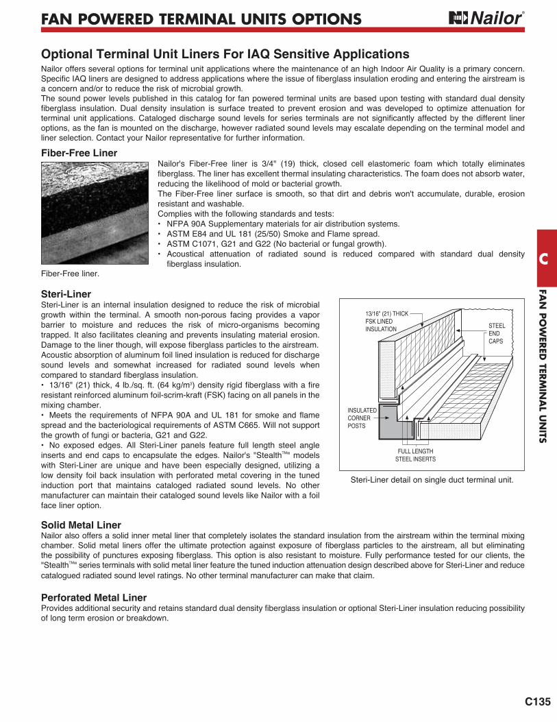
FAN
PO
WER
ED TER
MIN
AL U
NITS
C
C135
FAN POWERED TERMINAL UNITS OPTIONS
Fiber-Free LinerNailor's Fiber-Free liner is 3/4" (19) thick, closed cell elastomeric foam which totally eliminates
reducing the likelihood of mold or bacterial growth.The Fiber-Free liner surface is smooth, so that dirt and debris won't accumulate, durable, erosion resistant and washable.Complies with the following standards and tests:• NFPA 90A Supplementary materials for air distribution systems. • ASTM E84 and UL 181 (25/50) Smoke and Flame spread.• ASTM C1071, G21 and G22 (No bacterial or fungal growth).• Acoustical attenuation of radiated sound is reduced compared with standard dual density
Optional Terminal Unit Liners For IAQ Sensitive Applications
Fiber-Free liner.
Steri-LinerSteri-Liner is an internal insulation designed to reduce the risk of microbial growth within the terminal. A smooth non-porous facing provides a vapor barrier to moisture and reduces the risk of micro-organisms becoming trapped. It also facilitates cleaning and prevents insulating material erosion.
Acoustic absorption of aluminum foil lined insulation is reduced for discharge sound levels and somewhat increased for radiated sound levels when
• 13/16" (21) thick, 4 lb./sq. ft. (64 kg/m3
resistant reinforced aluminum foil-scrim-kraft (FSK) facing on all panels in the mixing chamber.
spread and the bacteriological requirements of ASTM C665. Will not support the growth of fungi or bacteria, G21 and G22.• No exposed edges. All Steri-Liner panels feature full length steel angle inserts and end caps to encapsulate the edges. Nailor's "StealthTM" models with Steri-Liner are unique and have been especially designed, utilizing a low density foil back insulation with perforated metal covering in the tuned induction port that maintains cataloged radiated sound levels. No other manufacturer can maintain their cataloged sound levels like Nailor with a foil face liner option.
INSULATEDCORNERPOSTS
FULL LENGTHSTEEL INSERTS
STEELENDCAPS
13/16" (21) THICKFSK LINEDINSULATION
Steri-Liner detail on single duct terminal unit.
Nailor offers several options for terminal unit applications where the maintenance of an high Indoor Air Quality is a primary concern.
a concern and/or to reduce the risk of microbial growth. The sound power levels published in this catalog for fan powered terminal units are based upon testing with standard dual density
options, as the fan is mounted on the discharge, however radiated sound levels may escalate depending on the terminal model and liner selection. Contact your Nailor representative for further information.
Solid Metal LinerNailor also offers a solid inner metal liner that completely isolates the standard insulation from the airstream within the terminal mixing
"StealthTM" series terminals with solid metal liner feature the tuned induction attenuation design described above for Steri-Liner and reduce catalogued radiated sound level ratings. No other terminal manufacturer can make that claim.
Perforated Metal Liner
of long term erosion or breakdown.

DIRECT DIGITAL CONTROLS (DDC)
F9
CO
NTR
OLS
F
Control Sequence N300Models: 35S, 35SST, 37S and 37SSTCooling (Plenum Heat Only), Constant Volume
1. Changeover/Morning Warm-up (Central AHU Heat/ Cool): If supply air as measured by the discharge air temperature (DAT) sensor is below 72°F (22.2°C), cool air is said to be available. If supply air is above 76°F (24.4°C), warm air is said to be available. 2.Cool Air Available: As space temperature rises
MINIMUM HEATING CFM
INDUCED AIR
TOTAL AIR
HTG.SP
CLG.SP
ROOM TEMP. INCREASE
CFM
INCR
EASE
MAX. HTG. CFM
WARM AIR AVAILABLE SEQUENCE
HTG. SPAN
HTG.SP
CLG.SP
CLG. SPAN ROOM TEMP. INCREASE
HTG.SP
ROOM TEMP. INCREASE
MAX. COOLING CFM
CFM
INCR
EASE
COLD AIR AVAILABLE SEQUENCE
MINIMUM COOLING CFM
INDUCED AIR
TOTAL AIR FLOW
+2°F(+1.1°C)
-2°F(-1.1°C)
MAX. FANSPEED
FAN OPERATION
MIN. FANSPEED
FAN OFF
OCCUPIED
UNOCCUPIEDSTANDBY STANDBY
above the cooling setpoint, the controller increases primary airflow. At a space temperature of 2°F (1.1°C) above the cooling setpoint, maximum cooling airflow is maintained. On a decrease in space temperature, the controller reduces airflow. Below cooling setpoint, minimum airflow is maintained. 3. The fan is started during occupied and standby modes and runs continuously at maximum fan speed. The fan induces warm ceiling plenum air as the primary airflow varies and maintains a constant volume to the space. During unoccupied mode, the fan starts on a call for heating only. The fan stops only during unoccupied mode when there is no call for heat. EPIC ECM Motor Only:During standby and unoccupied modes, the fan runs at minimum fan speed.4. As the space temperature drops below the heating setpoint, the fan continues to recirculate warm ceiling plenum air.5. Warm Air Available: As space temperature drops below the heating setpoint, the controller increases primary airflow. At a space temperature of 2°F (1.1°C) below the heating setpoint, maximum heating airflow is maintained. On an increase in space temperature, airflow decreases. As space temperature rises above the heating setpoint, minimum heating airflow is maintained.
Standard Control Sequences • Fan Powered Terminal Units • Series FlowNailor EZvav • Pressure Independent
Control Sequence N302Models: 35SE, 35SEST, 35SW, 35SWST, 37SE, 37SEST, 37SW and 37SWSTCooling with Modulating Heat, Constant Volume
1. Changeover/Morning Warm-up (Central AHU Heat/Cool): If supply air as measured by the discharge air temperature (DAT) sensor is below 72°F (22.2°C), cool air is said to be available. Ifsupply air is above 76°F (24.4°C), warm air is said to be available. Any time warm air is available, auxiliary heat is locked out.2. Cool Air Available: As space temperature rises above the cooling setpoint, the controller increases primary airflow. At a space temperature of 2°F (1.1°C) above the cooling setpoint, maximum cooling airflow is maintained. On a decrease in space temperature, the controller reduces airflow. Below cooling setpoint, minimum airflow is maintained. 3. The fan is started during occupied and standby modes and runs continuously at maximum fan speed. The fan induces warm ceiling plenum air as the primary airflow varies and maintains a constant volume to the space. During unoccupied mode, the fan starts on a call for heating only. The fan stops only during unoccupied mode when there is no call for heat. EPIC ECM Motor Only: During standby and unoccupied modes, the fan runs at minimum fan speed.4. Supplemental Heat: As the space temperature drops below the heating setpoint, the heating output modulates open. As the space temperature rises towards the heating setpoint, the heating modulates closed. If the heating loop is less than 10%, the heating output remains at 0%.5. If DAT limiting is enabled and a DAT sensor is detected, the discharge air heating setpoint is determined based on the heating loop. The dischargetemperature is limited to 15°F (8.3°C) above space temperature up to a maximum of 90°F (32.2°C).6. Warm Air Available: As space temperature drops below the heating setpoint, the controller increases primary airflow. At a space temperature of 2°F (1.1°C) below the heating setpoint, maximum heating airflow is maintained. On an increase in space temperature, airflow decreases. As space temperature rises above the heating setpoint, minimum heating airflow is maintained.
HTG.SP
CLG.SP
CLG. SPAN ROOM TEMP. INCREASE
HTG.SP
ROOM TEMP. INCREASE
MAX. COOLING CFM
CFM
INCR
EASE
COLD AIR AVAILABLE SEQUENCE
HTG. SPAN
MINIMUM COOLING CFM
INDUCED AIR
TOTAL AIR FLOW
-2°F(-1.1°C)
+2°F(+1.1°C)
MINIMUM HEATING CFM
INDUCED AIR
TOTAL AIR
HTG.SP
CLG.SP
ROOM TEMP. INCREASE
CFM
INCR
EASE
MAX. HTG. CFM
WARM AIR AVAILABLE SEQUENCE
HTG. SPAN
-2°F(-1.1°C)
MODULATING HEAT OPERATION
ROOM TEMP. INCREASE
HTG.SP
HTG. SPAN
-2°F(-1.1°C)
LOOP
%
0
100
10
HTG. %
HEAT
MAX. FANSPEED
FAN OPERATION
MIN. FANSPEED
FAN OFF
OCCUPIED
UNOCCUPIEDSTANDBY STANDBY
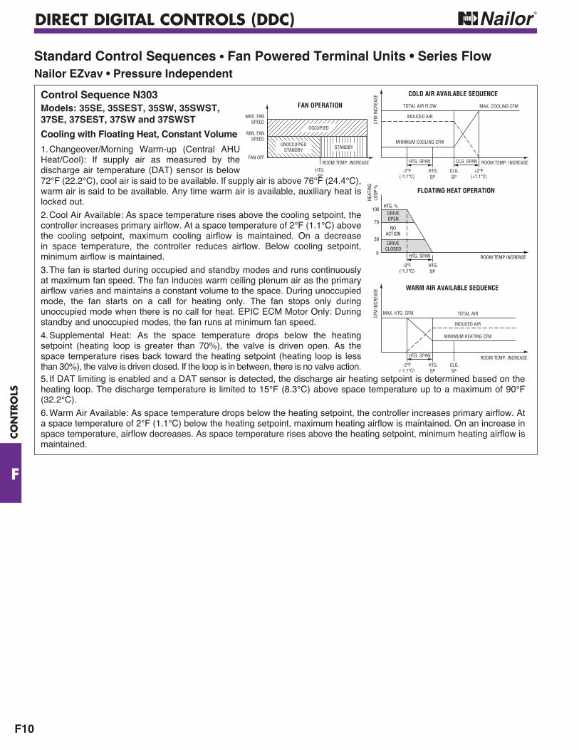
DIRECT DIGITAL CONTROLS (DDC)
F10
CO
NTR
OLS
F
Standard Control Sequences • Fan Powered Terminal Units • Series FlowNailor EZvav • Pressure Independent
Control Sequence N303Models: 35SE, 35SEST, 35SW, 35SWST, 37SE, 37SEST, 37SW and 37SWST
Cooling with Floating Heat, Constant Volume
1. Changeover/Morning Warm-up (Central AHU Heat/Cool): If supply air as measured by the discharge air temperature (DAT) sensor is below72°F (22.2°C), cool air is said to be available. If supply air is above 76°F (24.4°C), warm air is said to be available. Any time warm air is available, auxiliary heat is locked out.
2. Cool Air Available: As space temperature rises above the cooling setpoint, the controller increases primary airflow. At a space temperature of 2°F (1.1°C) above the cooling setpoint, maximum cooling airflow is maintained. On a decrease in space temperature, the controller reduces airflow. Below cooling setpoint, minimum airflow is maintained.
3. The fan is started during occupied and standby modes and runs continuously at maximum fan speed. The fan induces warm ceiling plenum air as the primary airflow varies and maintains a constant volume to the space. During unoccupied mode, the fan starts on a call for heating only. The fan stops only during unoccupied mode when there is no call for heat. EPIC ECM Motor Only: During standby and unoccupied modes, the fan runs at minimum fan speed.
4. Supplemental Heat: As the space temperature drops below the heating setpoint (heating loop is greater than 70%), the valve is driven open. As the space temperature rises back toward the heating setpoint (heating loop is less than 30%), the valve is driven closed. If the loop is in between, there is no valve action.5. If DAT limiting is enabled and a DAT sensor is detected, the discharge air heating setpoint is determined based on the heating loop. The discharge temperature is limited to 15°F (8.3°C) above space temperature up to a maximum of 90°F (32.2°C).
6. Warm Air Available: As space temperature drops below the heating setpoint, the controller increases primary airflow. At a space temperature of 2°F (1.1°C) below the heating setpoint, maximum heating airflow is maintained. On an increase in space temperature, airflow decreases. As space temperature rises above the heating setpoint, minimum heating airflow is maintained.
HTG.SP
CLG.SP
CLG. SPAN ROOM TEMP. INCREASE
HTG.SP
ROOM TEMP. INCREASE
MAX. COOLING CFM
CFM
INCR
EASE
COLD AIR AVAILABLE SEQUENCE
HTG. SPAN
MINIMUM COOLING CFM
INDUCED AIR
TOTAL AIR FLOW
-2°F(-1.1°C)
+2°F(+1.1°C)
MINIMUM HEATING CFM
HTG.SP
CLG.SP
ROOM TEMP. INCREASE
CFM
INCR
EASE
MAX. HTG. CFM
WARM AIR AVAILABLE SEQUENCE
HTG. SPAN
TOTAL AIR
INDUCED AIR
-2°F(-1.1°C)
MAX. FANSPEED
FAN OPERATION
MIN. FANSPEED
FAN OFF
OCCUPIED
UNOCCUPIEDSTANDBY STANDBY
FLOATING HEAT OPERATION
ROOM TEMP INCREASE
HTG.SP
HTG. SPAN
-2°F(-1.1°C)
LOOP
%
0
100
30
HTG. %
NOACTION
DRIVEOPEN
DRIVECLOSED
HEAT
ING
70
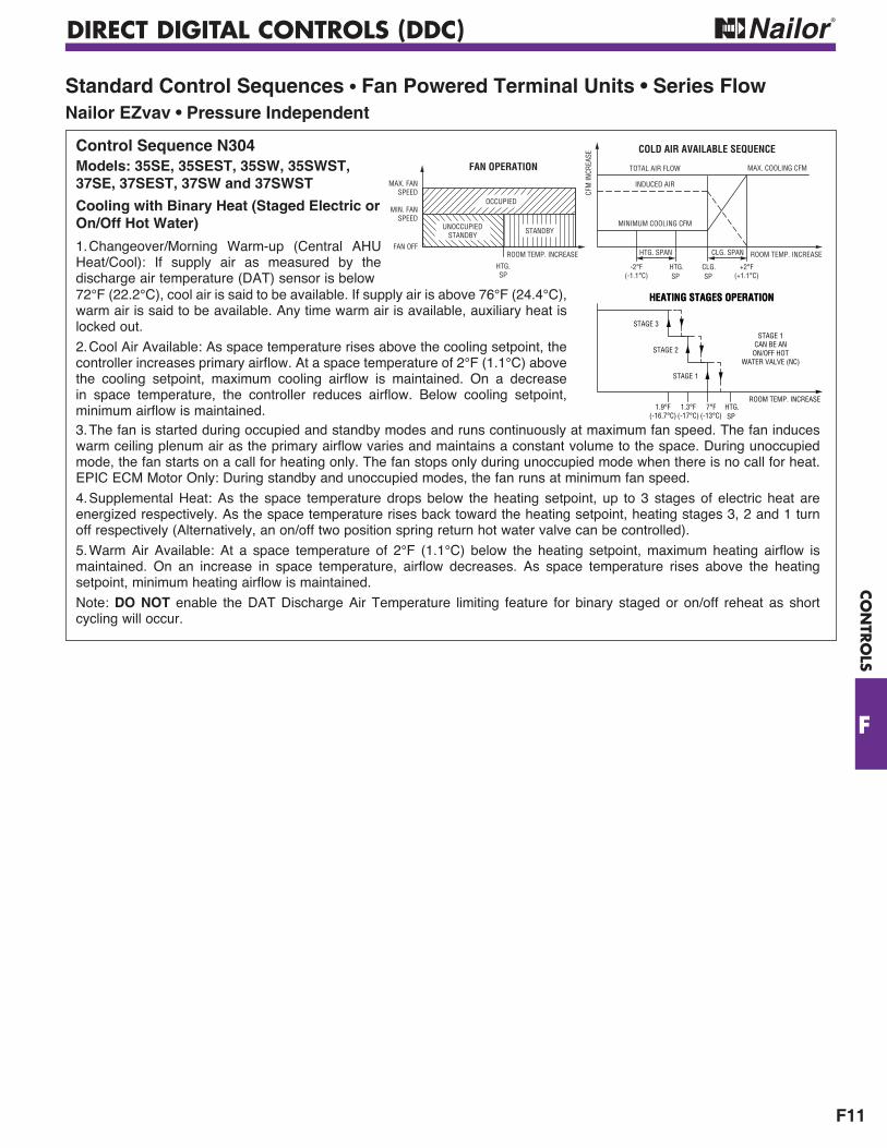
DIRECT DIGITAL CONTROLS (DDC)
F11
CO
NTR
OLS
F
Standard Control Sequences • Fan Powered Terminal Units • Series FlowNailor EZvav • Pressure Independent
Control Sequence N304Models: 35SE, 35SEST, 35SW, 35SWST, 37SE, 37SEST, 37SW and 37SWST
Cooling with Binary Heat (Staged Electric or On/Off Hot Water)
1. Changeover/Morning Warm-up (Central AHU Heat/Cool): If supply air as measured by the discharge air temperature (DAT) sensor is below72°F (22.2°C), cool air is said to be available. If supply air is above 76°F (24.4°C), warm air is said to be available. Any time warm air is available, auxiliary heat is locked out.
2. Cool Air Available: As space temperature rises above the cooling setpoint, the controller increases primary airflow. At a space temperature of 2°F (1.1°C) above the cooling setpoint, maximum cooling airflow is maintained. On a decrease in space temperature, the controller reduces airflow. Below cooling setpoint, minimum airflow is maintained. 3. The fan is started during occupied and standby modes and runs continuously at maximum fan speed. The fan induces warm ceiling plenum air as the primary airflow varies and maintains a constant volume to the space. During unoccupied mode, the fan starts on a call for heating only. The fan stops only during unoccupied mode when there is no call for heat. EPIC ECM Motor Only: During standby and unoccupied modes, the fan runs at minimum fan speed.
4. Supplemental Heat: As the space temperature drops below the heating setpoint, up to 3 stages of electric heat are energized respectively. As the space temperature rises back toward the heating setpoint, heating stages 3, 2 and 1 turn off respectively (Alternatively, an on/off two position spring return hot water valve can be controlled).
5. Warm Air Available: At a space temperature of 2°F (1.1°C) below the heating setpoint, maximum heating airflow is maintained. On an increase in space temperature, airflow decreases. As space temperature rises above the heating setpoint, minimum heating airflow is maintained.
Note: DO NOT enable the DAT Discharge Air Temperature limiting feature for binary staged or on/off reheat as short cycling will occur.
HTG.SP
CLG.SP
CLG. SPAN ROOM TEMP. INCREASE
HTG.SP
ROOM TEMP. INCREASE
MAX. COOLING CFM
CFM
INCR
EASE
COLD AIR AVAILABLE SEQUENCE
HTG. SPAN
MINIMUM COOLING CFM
INDUCED AIR
TOTAL AIR FLOW
-2°F(-1.1°C)
+2°F(+1.1°C)
MAX. FANSPEED
FAN OPERATION
MIN. FANSPEED
FAN OFF
OCCUPIED
UNOCCUPIEDSTANDBY STANDBY
HEATING STAGES OPERATIONHEATING STAGES OPERATION
ROOM TEMP. INCREASEHTG.SP
1.9°F(-16.7°C)
1.3°F(-17°C)
7°F(-13°C)
STAGE 3
STAGE 2
STAGE 1
STAGE 1CAN BE AN
ON/OFF HOTWATER VALVE (NC)
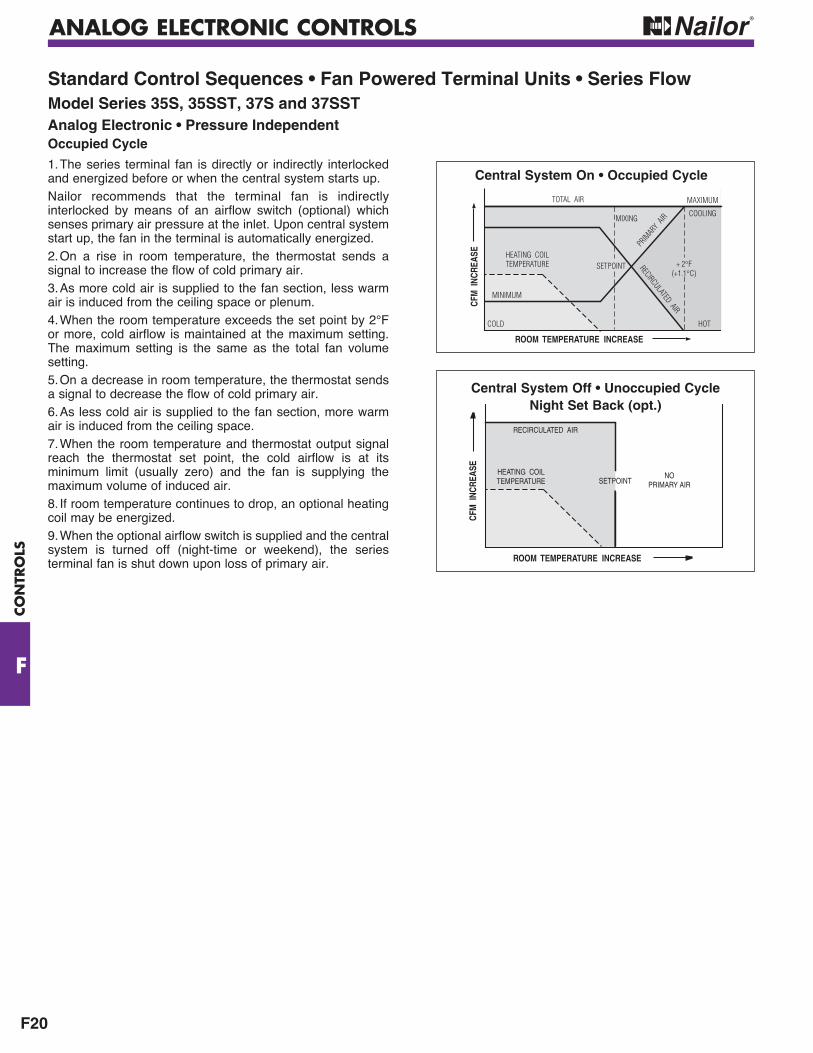
ANALOG ELECTRONIC CONTROLS
F20
CO
NTR
OLS
F
Standard Control Sequences • Fan Powered Terminal Units • Series FlowModel Series 35S, 35SST, 37S and 37SSTAnalog Electronic • Pressure IndependentOccupied Cycle
1. The series terminal fan is directly or indirectly interlocked and energized before or when the central system starts up.Nailor recommends that the terminal fan is indirectly interlocked by means of an airflow switch (optional) which senses primary air pressure at the inlet. Upon central system start up, the fan in the terminal is automatically energized.2. On a rise in room temperature, the thermostat sends a signal to increase the flow of cold primary air.3. As more cold air is supplied to the fan section, less warm air is induced from the ceiling space or plenum.4. When the room temperature exceeds the set point by 2°F or more, cold airflow is maintained at the maximum setting. The maximum setting is the same as the total fan volume setting.5. On a decrease in room temperature, the thermostat sends a signal to decrease the flow of cold primary air.6. As less cold air is supplied to the fan section, more warm air is induced from the ceiling space.7. When the room temperature and thermostat output signal reach the thermostat set point, the cold airflow is at its minimum limit (usually zero) and the fan is supplying the maximum volume of induced air.8. If room temperature continues to drop, an optional heating coil may be energized.9. When the optional airflow switch is supplied and the central system is turned off (night-time or weekend), the series terminal fan is shut down upon loss of primary air.
TOTAL AIR MAXIMUM
MINIMUM
COLD HOT
PRIM
ARY
AIR
ROOM TEMPERATURE INCREASE
SETPOINT
CFM
INC
REAS
E
RECIRCULATED AIR
HEATING COILTEMPERATURE
MIXINGCOOLING
+ 2°F(+1.1°C)
SETPOINT
ROOM TEMPERATURE INCREASE
CFM
INC
REAS
E
RECIRCULATED AIR
HEATING COILTEMPERATURE
NOPRIMARY AIR
Central System On • Occupied Cycle
Central System Off • Unoccupied Cycle Night Set Back (opt.)
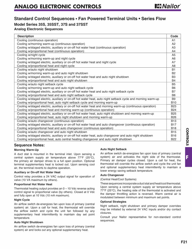
ANALOG ELECTRONIC CONTROLS
F21
CO
NTR
OLS
F
Standard Control Sequences • Fan Powered Terminal Units • Series FlowModel Series 35S, 35SST, 37S and 37SSTAnalog Electronic Sequences
Sequence Notes:Morning Warm-UpA duct stat is mounted in the terminal inlet. Upon sensing a central system supply air temperature above 77°F (25°C), the primary air damper drives to a full open position. Optional terminal supplementary heat is locked out. Upon sensing cool air, the terminal reverts to daytime operation.
Auxiliary or On-off Hot Water HeatControl relay provides a 24 VAC output signal for operation of valve (10 VA maximum by others).
Proportional Hot Water Heat Thermostat heating output provides an 0 – 10 Vdc reverse acting control signal to proportional valve (by others). Closed at 0 Vdc and fully open at 10 Vdc (10 mA maximum).
Night Cycle An airflow switch de-energizes fan upon loss of primary (central system) air. Upon a call for heat, the thermostat will override the airflow switch and cycle the unit fan followed by any supplementary heat intermittently to maintain day set point temperature.
Auto Night ShutdownAn airflow switch de-energizes fan upon loss of primary (central system) air and locks out any optional supplementary heat.
Auto Night SetbackAn airflow switch de-energizes fan upon loss of primary (central system) air and activates the night side of the thermostat. Primary air damper cycles closed. Upon a call for heat, the thermostat will override the airflow switch and cycle the unit fan and optional supplementary heat intermittently to maintain a lower energy saving setback temperature.
Auto Changeover(Central Heat/Cool Systems)
These sequences incorporate a duct stat and heat/cool thermostat. Upon sensing a central system supply air temperature above 77°F (25°C), the heating side of the thermostat is activated and the damper throttling action is reversed. Warm central air is modulated between minimum and maximum set points.
Optional StrategiesNight setback, night shutdown and primary damper overrides may be initiated by external 24 VAC inputs and/or dry contact closures.
Consult your Nailor representative for non-standard control sequences.
Description CodeCooling (continuous operation) A1Cooling w/morning warm-up (continuous operation) A2Cooling w/staged electric, auxiliary or on-off hot water heat (continuous operation) A3Cooling w/proportional heat (continuous operation) A4Cooling w/night cycle A5Cooling w/morning warm-up and night cycle A6Cooling w/staged electric, auxiliary or on-off hot water heat and night cycle A7Cooling w/proportional heat and night cycle A8Cooling w/auto night shutdown B1Cooling w/morning warm-up and auto night shutdown B2Cooling w/staged electric, auxiliary or on-off hot water heat and auto night shutdown B3Cooling w/proportional heat and auto night shutdown B4 Cooling w/auto night setback cycle B5Cooling w/morning warm-up and auto night setback cycle B6Cooling w/staged electric, auxiliary or on-off hot water heat and auto night setback cycle B7Cooling w/proportional heat and auto night setback cycle B8Cooling w/staged electric, auxiliary or on-off hot water heat, auto night setback cycle and morning warm-up B9Cooling w/proportional heat, auto night setback cycle and morning warm-up B10Cooling w/staged electric, auxiliary or on-off hot water heat and morning warm-up (continuous operation) B23Cooling w/proportional heat and morning warm-up (continuous operation) B24Cooling w/staged electric, auxiliary or on-off hot water heat, auto night shutdown and morning warm-up B25Cooling w/proportional heat, auto night shutdown and morning warm-up B26Cooling w/auto changeover (continuous operation) B13Cooling w/staged electric, auxiliary or on-off hot water heat and auto changeover (continuous operation) B17Cooling w/proportional heat and auto changeover (continuous operation) B18Cooling w/auto changeover and auto night shutdown B15Cooling w/staged electric, auxiliary or on-off hot water heat, auto changeover and auto night shutdown B16Cooling w/proportional heat, auto central heating changeover and auto night shutdown B22

ANALOG ELECTRONIC CONTROLS
F23
CO
NTR
OLS
F
DAMPEROPEN
PROP.BAND
COOL
ING
% O
PEN
DAMPERCLOSED(MIN.)
100
80
60
40
20
0
AIRF
LOW
INCR
EASE
ROOM TEMPERATURE INCREASE
SETPOINT
+3.2°F(1.8°C)
DIALSET POINTControl Sequence E2
Cooling OnlyCentral system supplies cool air. On a rise in room temperature above set point, the bypass damper will slowly modulate open, increasing the flow of air to the room, closing the bypass at the same time. On a fall in room temperature below set point, the bypass damper will modulate closed, reducing the flow of cool air into the room and opening the bypass at the same time. A mechanical air volume minimum stop is provided (field set).
Standard Control Sequences • Bypass Terminal UnitsAnalog Electronic • Pressure Dependent
Model 3400 or 34RW
Model 3400
Model 3400
Control Sequence E3Automatic Heating/Cooling ChangeoverThis arrangement is for systems supplying cool air in summer and hot air in winter. A duct temperature sensor senses inlet temperature and automatically reverses control action when supply air is above 78°F (26°C). A mechanical air volume minimum stop is provided (field set).
Cooling Mode:Supply air system in cooling mode (below 75°F (24°C)). On a rise in room temperature above set point, the bypass damper will modulate open, increasing the flow of cool air to the room, closing the bypass at the same time. On a fall in room temperature below set point, the bypass damper will modulate closed, reducing the flow of cool air into the room and opening the bypass at the same time.
Heating Mode:Supply air system in heating mode (above 78°F (26°C)). On a rise in room temperature above set point, the bypass damper will modulate closed, reducing the flow of warm air into the room to maintain set point and opening the bypass. On a fall in room temperature below set point, the bypass damper will modulate open, increasing the flow of warm air into the room to maintain the set point and closing the bypass at the same time.
Control Sequence E4Cooling with On/Off Auxiliary Heat (Perimeter) or Hot Water ReheatCentral system supplies cool air. On a rise in room temperature above set point, the bypass damper will slowly modulate open, increasing the flow of air to the room, closing the bypass at the same time. On a fall in room temperature below set point, the bypass damper will modulate closed, reducing the flow of cool air into the room and opening the bypass at the same time.
If room temperature continues to fall, the thermostat will energize the control relay/valve of the perimeter heating or hot water valve for reheat. A mechanical air volume minimum stop is provided (field set).
DAMPEROPEN
DAMPEROPEN
COOL
INGHEATING
% O
PEN
DAMPERCLOSED(MIN.)
100
80
60
40
20
0
AIRF
LOW
INCR
EASE
DIALSET POINT
ROOM TEMPERATURE INCREASE
SETPOINT
+3.2°F(1.8°C)
– 3.2°F(1.8°C)
DAMPEROPEN
ONCO
OLIN
G
PERIMETER OR HOT W
ATER REHEAT
% O
PEN
DAMPERCLOSED(MIN.)
100
80
60
40
20
0
DIALSET POINT
CENTERED INDEAD BAND
2F (1.1C)
OFF
PROP.BAND
PROP.BAND
ROOM TEMPERATURE INCREASE
+3.2°F(1.8°C)
– 3.2°F(1.8°C)
CSPHSP
AIRF
LOW
INCR
EASE
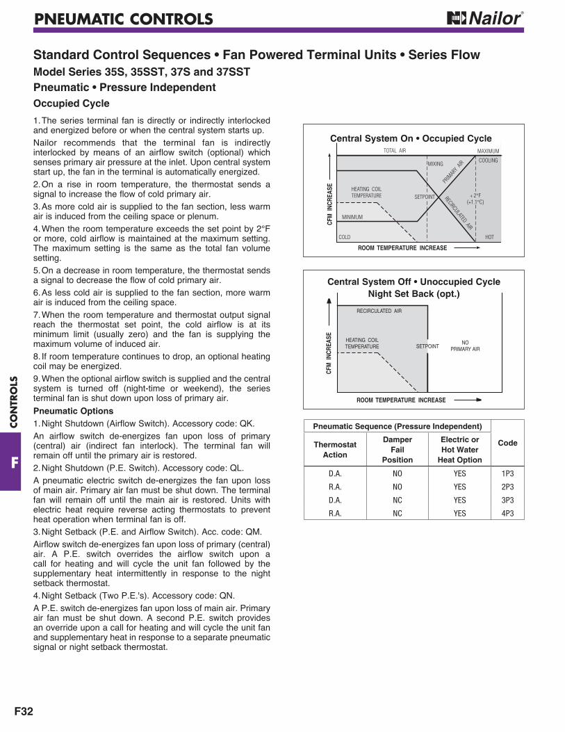
PNEUMATIC CONTROLS
F32
CO
NTR
OLS
F
Standard Control Sequences • Fan Powered Terminal Units • Series FlowModel Series 35S, 35SST, 37S and 37SSTPneumatic • Pressure IndependentOccupied Cycle
1. The series terminal fan is directly or indirectly interlocked and energized before or when the central system starts up.Nailor recommends that the terminal fan is indirectly interlocked by means of an airflow switch (optional) which senses primary air pressure at the inlet. Upon central system start up, the fan in the terminal is automatically energized.2. On a rise in room temperature, the thermostat sends a signal to increase the flow of cold primary air.3. As more cold air is supplied to the fan section, less warm air is induced from the ceiling space or plenum.4. When the room temperature exceeds the set point by 2°F or more, cold airflow is maintained at the maximum setting. The maximum setting is the same as the total fan volume setting.5. On a decrease in room temperature, the thermostat sends a signal to decrease the flow of cold primary air.6. As less cold air is supplied to the fan section, more warm air is induced from the ceiling space.7. When the room temperature and thermostat output signal reach the thermostat set point, the cold airflow is at its minimum limit (usually zero) and the fan is supplying the maximum volume of induced air.8. If room temperature continues to drop, an optional heating coil may be energized.9. When the optional airflow switch is supplied and the central system is turned off (night-time or weekend), the series terminal fan is shut down upon loss of primary air.
Pneumatic Options1. Night Shutdown (Airflow Switch). Accessory code: QK.An airflow switch de-energizes fan upon loss of primary (central) air (indirect fan interlock). The terminal fan will remain off until the primary air is restored.2. Night Shutdown (P.E. Switch). Accessory code: QL.A pneumatic electric switch de-energizes the fan upon loss of main air. Primary air fan must be shut down. The terminal fan will remain off until the main air is restored. Units with electric heat require reverse acting thermostats to prevent heat operation when terminal fan is off.3. Night Setback (P.E. and Airflow Switch). Acc. code: QM.Airflow switch de-energizes fan upon loss of primary (central) air. A P.E. switch overrides the airflow switch upon a call for heating and will cycle the unit fan followed by the supplementary heat intermittently in response to the night setback thermostat.4. Night Setback (Two P.E.'s). Accessory code: QN.A P.E. switch de-energizes fan upon loss of main air. Primary air fan must be shut down. A second P.E. switch provides an override upon a call for heating and will cycle the unit fan and supplementary heat in response to a separate pneumatic signal or night setback thermostat.
TOTAL AIR MAXIMUM
MINIMUM
COLD HOT
PRIM
ARY
AIR
ROOM TEMPERATURE INCREASE
SETPOINT
CFM
INC
REAS
E
RECIRCULATED AIR
HEATING COILTEMPERATURE
MIXINGCOOLING
+ 2°F(+1.1°C)
SETPOINT
ROOM TEMPERATURE INCREASE
CFM
INC
REAS
E
RECIRCULATED AIR
HEATING COILTEMPERATURE
NOPRIMARY AIR
Central System On • Occupied Cycle
Central System Off • Unoccupied Cycle Night Set Back (opt.)
Pneumatic Sequence (Pressure Independent)
CodeThermostat Action
Damper Fail
Position
Electric or Hot Water
Heat Option
D.A. NO YES 1P3
R.A. NO YES 2P3
D.A. NC YES 3P3
R.A. NC YES 4P3

SUGGESTED SPECIFICATIONS
G24
G
SUG
GES
TED
SPEC
IFIC
ATI
ON
S
Model 37S • Series Flow (Constant or (continued)
OPTIONS"STEALTHTM"(Substitute the following paragraphs:)1. Furnish and install series flow (constant or variable volume) fan powered terminal units of the sizes and capacities as indicated on the drawings. Units shall be pressure independent with (digital electronic, analog electronic, pneumatic) controls. Units shall be manufactured by Nailor Industries Inc. Model 37SST "StealthTM".4. Unit maximum radiated sound power levels at 1.0" w.g. (249 Pa) inlet pressure and 0.25" w.g. (63 Pa) discharge static pressure shall not exceed the values in Tables 4 and 5 at the specified airflow. No credit or reduction shall in any way be considered for room, plenum, ceiling and/or similar item effects.
Table 4. Maximum Radiated Sound Power Levels Full Cooling (Fan on and 100% primary air)
Table 5. Maximum Radiated Sound Power Levels Full Heating (Fan only)15. Unit maximum discharge sound power levels at 1.0" w.g. (249 Pa) inlet pressure and 0.25" w.g. (63 Pa) discharge static pressure shall not exceed the values in Table 6 at the specified airflow. No credit or reduction shall in any way be considered for room, downstream duct, elbows and/or similar item effects.
Table 6. Maximum Discharge Sound Power Levels Full cooling (Fan on and 100% primary air)
Electric Heat (Substitute the following paragraphs:)1. Furnish and install series flow (constant or variable volume) fan powered terminal units with integral electric heat of the sizes and capacities as indicated on the drawings. Units shall be pressure independent with (pneumatic, analog electronic, digital electronic) controls. Units shall be manufactured by Nailor Industries Inc. Model 37SE or 37SEST "StealthTM" (select one).12. An electric heater shall be factory mounted and pre-wired as an integral package with the fan powered terminal unit. Heaters shall be sized as shown on the drawings. The entire assembly including the electric heater shall be ETL listed (cETL in Canada) for zero clearance and so labeled and shall meet all requirements of the latest National Electrical Code (Canadian Electrical Code, CSA Standard C22.1). The
unit with the heater mounted shall be listed and rated to be turned over for either left or right hand configuration. The unit shall have a single point electrical (and pneumatic) connection. Heater casing and panel shall be a minimum of 20 gauge galvanized steel. Each heater shall be complete with primary disc type automatic high limit, contactors as required, ground terminal, fan relay for interlocking the heater and fan and high grade nickel chrome alloy resistance wire. Element wires shall be suspended in insulators designed to expose the entire face area of the wire thereby eliminating hot spots. Each heater shall be supplied with factory supplied and pre-wired branch circuit fusing as required by NEC and UL. Circuiting and fusing shall also be in accordance with the circuiting requirements as shown on the plans. Additional accessories shall include (control transformer, circuit fusing, disconnect switch, electric step controller, pneumatic electric switches) for staging the heater. (Additional performance requirements that you might want to include can be found in the electric heater section). The electric heater shall be located on the discharge side of the fan so as not to add heat to the motor and shorten its expected lifetime.
Heater voltage and stages to be as follows: 0 to 5.0 kW ..................................... 277V/1 phase, 1 Step5.1 kW and up ................................ 480V/3 phase, 1 Step
Hot Water Heating Coils(Substitute the following paragraphs:)1. Furnish and install series flow (constant or variable volume) fan powered terminal units with integral hot water coils of the sizes and capacities as indicated on the drawings. Units shall be pressure independent with (digital electronic, analog electronic, pneumatic) controls. Units shall be manufactured by Nailor Industries Inc. Model 37SW or 37SWST "StealthTM" (select one).12. A hot water coil shall be factory mounted as an integral package with the fan powered terminal unit. Hot water coils shall be sized as shown on the drawings. The entire assembly including the hot water coil shall be ETL listed (cETL in Canada) for zero clearance and so labeled and shall meet all requirements of the latest National Electrical Code. The unit shall have a single point electrical (and pneumatic) connection. Water coil casing and panels shall be a minimum of 20 ga. (1.00) galvanized steel. Access panels shall be supplied on the top and bottom of the unit for easy access to the coil for inspection and cleaning. All copper, including the headers and return bends, shall be encased to eliminate heat loss during heating sequence and heat gain during cooling sequence. Coils shall be 1, 2 or 3 row as required and heating capacities shall be as shown on the plans. Coils shall have aluminum plate fins spaced 10 per inch and bonded to 1/2" (13) O.D. copper tubes. Copper connections shall be sweat. All coils shall be tested at a minimum of 300 psi (2.1 MPa) under water to produce a guaranteed working pressure of 250 psi (1.7 MPa). Controls and valves for the hot water coils shall be field mounted. Heating coils shall be located on the discharge side of the fan so as not to add heat to the motor and shorten its expected lifetime.
EZvav Digital Controls 1.1 ASC VAV BACnet CONTROLLERS
A. Digital VAV Controllers shall be responsible for monitoring and controlling directly connected VAV Terminals as required. Controllers shall include fully adjustable analog outputs and digital outputs as required utilizing a proportional plus integral control loop to control damper, electric heat and hot water coils for the purpose of maintaining
B. The VAV controller shall be available with integrated applications (based on model) for Single Duct, Dual Duct, and Fan Powered terminal units, including any of the following as required by the control sequence. For Single/Dual Duct terminals: Cooling Only, Cooling/Heating with Changeover and Morning Warm up. For Fan Powered terminals: Cooling with Reheat/Supplementary Heat, Heating coil
Fan Powered Terminal Units • 37S Series
UnitSize
Airflow Sound Power Octave Band Center Frequency (Hz.)
cfm l/s 2 3 4 5 6 7125 250 500 1000 2000 4000
1 300 142 58 54 47 42 38 332 700 330 65 60 54 52 49 463 900 425 67 60 54 50 43 404 1450 684 70 62 56 51 48 46
UnitSize
Airflow Sound Power Octave Band Center Frequency (Hz.)
cfm l/s 2 3 4 5 6 7125 250 500 1000 2000 4000
1 300 142 55 51 44 38 33 262 700 330 62 55 52 48 39 333 900 425 64 58 55 53 41 344 1450 684 67 58 53 49 43 36
UnitSize
Airflow Sound Power Octave Band Center Frequency (Hz.)
cfm l/s 2 3 4 5 6 7125 250 500 1000 2000 4000
1 300 142 66 62 54 46 41 362 700 330 66 62 59 55 51 463 900 425 77 72 67 66 62 594 1450 684 75 71 70 69 66 63

SUGGESTED SPECIFICATIONS
G25
SUG
GESTED
SPEC
IFICA
TION
S
G
Fan Powered Terminal Units
37S Series OPTIONS (continued)
Sensor, including communication parameters (instance, MAC, baud)
based software. VAV controllers shall not require the use of a personal computer and PC based software and/or any interface modules.
D.The VAV controller shall be capable of being balanced from the
E.The controller shall have integrated MS/TP communications. The communication port shall have network protection bulbs and integrated end-of-line (EOL) terminations.
F.The controller shall have an integrated actuator rated at 40 in-lbs. Connection to the damper shall be with a v-bolt clamp, accepting 3/8" to 5/8" damper shaft sizes. The actuator shall travel 0 to 95 degrees with adjustable end stops at 45 and 60 degrees of rotation. The actuator shall have an integrated gear disengagement mechanism.
G.The controller shall have an integrated transducer pressure sensor for airflow measurement. The sensor shall have a range or 0-2"wc, consuming and accurate to 4.5% of reading or 0.0008"wc, whichever is greater.
H.The controller shall have a Dedicated Room Sensor port for direct interface to a Digital Display Room Sensor or Discrete Room Sensor. The controller shall have the ability of detecting if a sensor has been connected to the port and identify its type, either digital display or discrete. Sensors shall be hot-swappable without powering down the controller. Sensor information via the ports shall not consume any of the devices terminated input capacity.
I.The controller shall have screw terminal blocks that can accommodate wire sizes 14-22 AWG. Terminals shall be color coded: black terminals for power, green terminals for input and outputs, and grey terminals for twisted-shielded-pair communication.
J. The power supply for the controller shall be 24 volts AC (-15%, +20%) power. Voltage below the operating range of the system shall be considered an outage.
1.2 DIGITAL ROOM SENSOR
A. The Digital Display Room Sensor (thermostat) shall provide space condition measurements and indications, including temperature and local motion/occupancy (optional), and user setpoint adjustments.
B. The Digital Room Sensor shall connect directly to the controller and shall not utilize any of the hardware I/O points of the controller. The Digital Display Room Sensor shall be able to be located up to 75' from the controller.
C. The Digital Display Room Sensor shall provide a Temporary
for connection to the BACnet MS/TP communication trunk to which the devices connected. The Digital Display Room Sensor, the connected controller, and all other devices on the BACnet network shall be accessible through the temporary communication jack. Microprocessor based sensors whose port only allows communication with the controller to which it is connected shall not be acceptable.
D. The Digital Display Room Sensor shall have an integrated sensor for temperature measurement as standard and a second integrated sensor for motion/occupancy (optional).
E. User/Occupant setpoints may be adjusted via the Digital Display Room Sensor.
for all control sequences allowing access to communication and application parameters.
G. The Digital Display Room Sensor shall have two levels of password protection: One level to protect user setpoint adjustment, and one level
4 digits in length.
Model 35N • Parallel Flow (Variable Volume)1. Furnish and install variable volume parallel fan powered terminal units of the sizes and capacities as indicated on the drawings. Units shall be pressure independent with (digital, analog electronic, pneumatic) controls. Units shall be manufactured by Nailor Industries Inc. Model 35N.2. The entire terminal unit shall be designed and built as a single unit. The units shall be provided with a primary variable air volume damper that controls the air quantity in response to a (thermostat or digital controller/zone sensor). The units shall also include a fan that sequences on and off in response to the (thermostat or digital controller/zone sensor). The space limitations shall be reviewed carefully to ensure that all units will fit into the space allowed.3. Unit casings shall be 20 ga. (1.00) galvanized steel. Unit shall be fully lined with fiberglass insulation which shall be at least 3/4" (19) thick dual density insulation complying with NFPA 90 for fire and smoke resistivity and UL 181 for erosion. Any cut edges of insulation shall be coated with NFPA 90 approved sealant. 4. The terminal casing shall have full size bottom access panels for easy access to motor and blower assembly and for maintenance and replacement of parts without disturbing duct connections. Access panels shall be attached to casing with (screws, 1/4 turn fasteners). 5. Units shall have round inlets for the primary air connections and shall have a minimum 6" (152) deep inlet duct collar for field connection. Models with no heat or electric heat shall have rectangular outlets suitable for flanged duct connections. Models with hot water coils shall have a discharge opening with slip and drive connection. Casing shall have mounting area for hanging by sheet metal straps from a concrete slab.6. The damper shall be round and of laminated 2 x 20 ga. (1.00) galvanized steel construction with a peripheral gasket and a solid steel 1/2" (13) diameter shaft, pivoted in self-lubricating bronze oilite bearings. Damper leakage shall not exceed 2% of the terminal rated airflow at 3" w.g. (750 Pa) inlet static pressure.7. Entire terminal unit shall be factory assembled with (digital, analog electronic, pneumatic) controls. All components including all controls except the room (thermostat or zone sensor) and (pneumatic piping, field wiring) shall be factory installed and mounted with the unit.8. Provide a (digital, analog electronic, pneumatic) flow control device that will limit the maximum and minimum airflow to that scheduled on the drawings. Control of the terminal unit shall be pressure independent.9. The sequence of operation should be described here, if not part of the temperature controls specifications.10. Blower casings shall be constructed of heavy gauge coated steel. Blower wheel shall be forward curved centrifugal type, dynamically balanced and driven by direct drive, single speed split capacitor motors. Motors shall be suitable for 120 or 208 or 240 or 277 volt single phase power. Motors shall have built-in overload protection, bearings capable of low rpm oiling, permanently oiled bearings and a built-in, anti-backward rotation device. Fan assembly shall be mounted so as to isolate the casing from the motor and blower vibration at no less than four points. Isolation shall be supplied at the motor and at the blower mounting points. A gasketed backdraft damper shall be included on the fan discharge to preclude primary air leakage back into the plenum space.11. A solid state SCR fan speed controller sized and designed for the specific blower motor combination shall be provided to allow infinitely adjustable fan speed from the minimum voltage stop to the line voltage signal to the motor. A minimum voltage stop shall be employed to ensure that fan cannot run in stall mode.12. Units shall incorporate a single point electrical (and pneumatic) connection for the entire unit. All electrical components shall be ETL listed or recognized and installed in accordance with the National Electrical Code. All electrical components shall be mounted in a control box. The entire assembly shall be ETL listed and labeled to meet UL 1995 and CSA C22.2 No. 236.


![[XLS]FM Terms and Abbreviations Standard - Central … and... · Web viewAbbreviations Factory Factory mutual Fahrenheit Fan coil unit Fan powered terminal Far face Far side Fascia](https://img.pdfslide.us/doc/110x75/5afd87a07f8b9aa34d8d9f13/xlsfm-terms-and-abbreviations-standard-central-andweb-viewabbreviations.jpg)