Embed Size (px)
Citation preview

Installation Instructions
Falcon Electro-mechanical
Swing Operator Models: 8230 & 8240
2720 Tobey Drive Indianapolis, IN 46219 Phone: 1-800-526-2400 FAX: 800-248-1460
7401XX-00(1) © 2008 Ingersoll-Rand Company Limited
Page 2 of 14
General 2 Replacement Parts and System Components 2 1. Pre-Installation Site and Product Check 4 2. Operator Installation 5 3. Wiring 9 4. Arm and Cover Installation 10 5. Operational Check 12 6. Operator Adjustment 15 7. Release for Service 17 8. Falcon Software 18
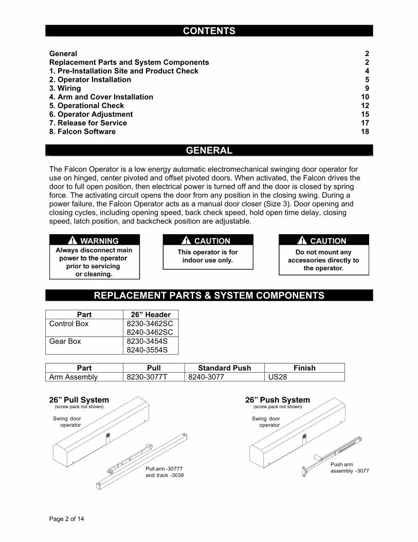
GENERAL The Falcon Operator is a low energy automatic electromechanical swinging door operator for use on hinged, center pivoted and offset pivoted doors. When activated, the Falcon drives the door to full open position, then electrical power is turned off and the door is closed by spring force. The activating circuit opens the door from any position in the closing swing. During a power failure, the Falcon Operator acts as a manual door closer (Size 3). Door opening and closing cycles, including opening speed, back check speed, hold open time delay, closing speed, latch position, and backcheck position are adjustable.
Part 26” Header
Control Box 8230-3462SC 8240-3462SC
Gear Box 8230-3454S 8240-3554S
Part Pull Standard Push Finish
Arm Assembly 8230-3077T 8240-3077 US28
CONTENTS
REPLACEMENT PARTS & SYSTEM COMPONENTS
26” Pull System(screw pack not shown)
26” Push System(screw pack not shown)
Page 3 of 14
1.1 Check that the Product Model is correct for the required application.
1.2 Check that all parts listed on the Bill of Material are in the shipping container.
1.3 Check the architectural drawings and final approved shop drawings for the position of frame and structural openings.
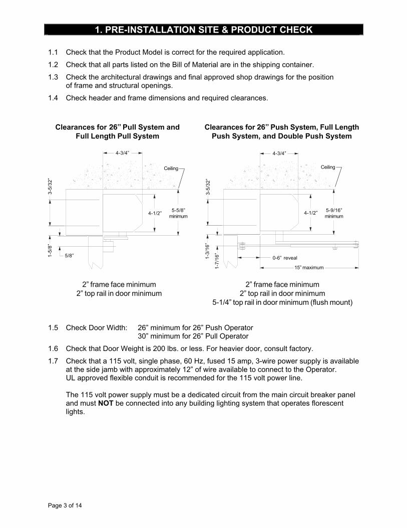
1.4 Check header and frame dimensions and required clearances.
26” 26”
1.5 Check Door Width: 26” minimum for 26” Push Operator
30” minimum for 26” Pull Operator
1.6 Check that Door Weight is 200 lbs. or less. For heavier door, consult factory.
1.7 Check that a 115 volt, single phase, 60 Hz, fused 15 amp, 3-wire power supply is available at the side jamb with approximately 12” of wire available to connect to the Operator. UL approved flexible conduit is recommended for the 115 volt power line. The 115 volt power supply must be a dedicated circuit from the main circuit breaker panel and must NOT be connected into any building lighting system that operates florescent lights.
1. PRE-INSTALLATION SITE & PRODUCT CHECK
Page 4 of 14
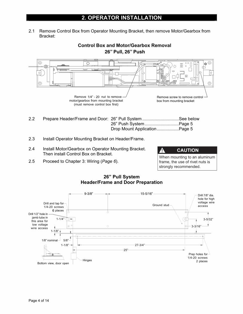
2.1 Remove Control Box from Operator Mounting Bracket, then remove Motor/Gearbox from Bracket:
1/4” - 20
26” Pull, 26” Push
Remove screw to remove controlbox from mounting bracket
2.2 Prepare Header/Frame and Door: 26” Pull System ..............................See below 26” Push System............................Page 5 Drop Mount Application ..................Page 5 2.3 Install Operator Mounting Bracket on Header/Frame.
2.4 Install Motor/Gearbox on Operator Mounting Bracket.
Then install Control Box on Bracket.
2.5 Proceed to Chapter 3: Wiring (Page 6).
26” Pull System Header/Frame and Door Preparation
9-3/8” 15-5/16”
6
2. OPERATOR INSTALLATION
CAUTIONWhen mounting to an aluminum frame, the use of rivet nuts is strongly recommended.
Page 5 of 14
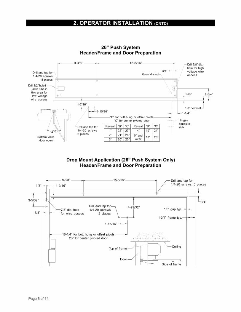
26” Push System Header/Frame and Door Preparation
9-3/8” 15-5/16”
Drop Mount Application (26” Push System Only) Header/Frame and Door Preparation
9-3/8” 15-5/16”
2. OPERATOR INSTALLATION (CNTD)
Page 6 of 14
TION 3.1 Refer to the appropriate wiring diagram for the Control Box (Page 14) or the diagram supplied for custom applications. Connect the following cables:
! Ground Cable (Ground the Operator properly with the earth from main supply)
! Hall Effect Cable (Do not wrap the Hall Effect Cable around the Motor Power Cable)
! Motor Power Cable (Do not wrap the Motor Power Cable around the Hall Effect Cable)
! Control Box Power Cable
3.2 Connect Activate and lock accessories, as needed. Refer to the accessory instructions for any accessories used. Do not connect any remote activating device to the door unless it is located within line of sight of the door. 3.3 When wiring is complete, proceed to Chapter 4: Arm and Cover Installation (Page 7)
3. WIRING
CAUTION
• Make sure all wires are properly dressed and secured to prevent interference
• Route all wiring away from moving parts, sharp edges, and heat sources
• Use copper conductors only
• Do not modify the factory wiring or connect into existing electrical circuits or devices
Page 7 of 14
WARNING
Keep hands, clothing, wires, tools, etc., AWAY FROM Operator Motor
when the Operator Motor is turned on
4.1 Make sure the Operator Powers is not connected.
4.2 Install a jumper across the control box Main Act and Main Act.
4.3 Connect power.
The operator motor will activate and drive to the Full Open position.
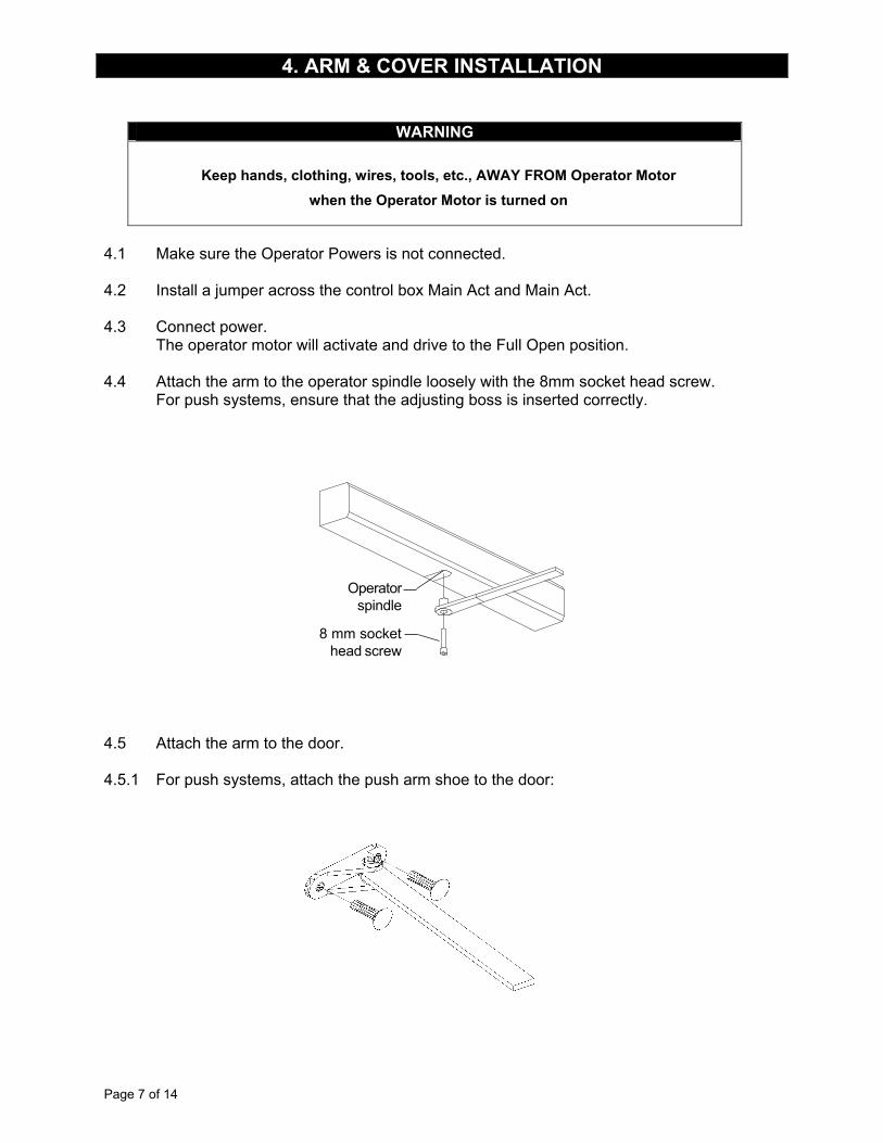
4.4 Attach the arm to the operator spindle loosely with the 8mm socket head screw. For push systems, ensure that the adjusting boss is inserted correctly.
Operatorspindle
8 mm sockethead screw
4.5 Attach the arm to the door. 4.5.1 For push systems, attach the push arm shoe to the door:
4. ARM & COVER INSTALLATION
Page 8 of 14
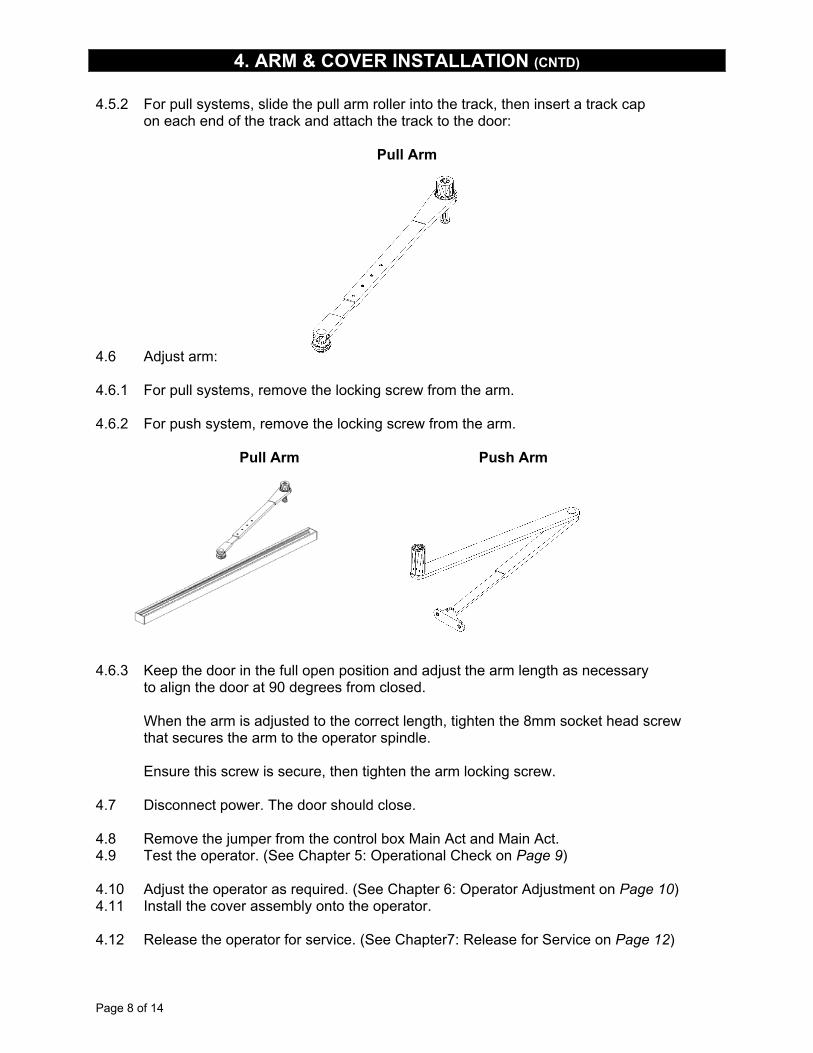
4.5.2 For pull systems, slide the pull arm roller into the track, then insert a track cap on each end of the track and attach the track to the door:
Pull Arm
4.6 Adjust arm: 4.6.1 For pull systems, remove the locking screw from the arm. 4.6.2 For push system, remove the locking screw from the arm. Pull Arm Push Arm
4.6.3 Keep the door in the full open position and adjust the arm length as necessary to align the door at 90 degrees from closed. When the arm is adjusted to the correct length, tighten the 8mm socket head screw that secures the arm to the operator spindle. Ensure this screw is secure, then tighten the arm locking screw. 4.7 Disconnect power. The door should close. 4.8 Remove the jumper from the control box Main Act and Main Act. 4.9 Test the operator. (See Chapter 5: Operational Check on Page 9) 4.10 Adjust the operator as required. (See Chapter 6: Operator Adjustment on Page 10) 4.11 Install the cover assembly onto the operator. 4.12 Release the operator for service. (See Chapter7: Release for Service on Page 12)
4. ARM & COVER INSTALLATION (CNTD)
Page 9 of 14
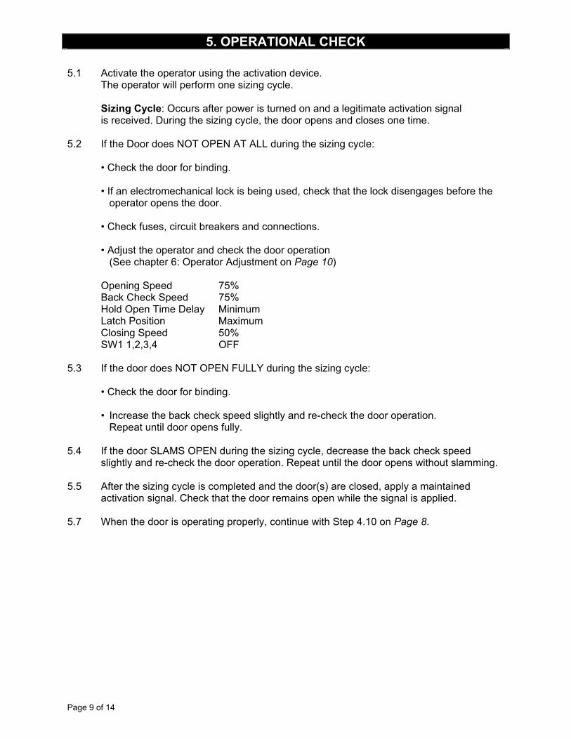
5.1 Activate the operator using the activation device. The operator will perform one sizing cycle. Sizing Cycle: Occurs after power is turned on and a legitimate activation signal is received. During the sizing cycle, the door opens and closes one time. 5.2 If the Door does NOT OPEN AT ALL during the sizing cycle: • Check the door for binding. • If an electromechanical lock is being used, check that the lock disengages before the operator opens the door. • Check fuses, circuit breakers and connections. • Adjust the operator and check the door operation (See chapter 6: Operator Adjustment on Page 10) Opening Speed 75% Back Check Speed 75% Hold Open Time Delay Minimum Latch Position Maximum Closing Speed 50% SW1 1,2,3,4 OFF 5.3 If the door does NOT OPEN FULLY during the sizing cycle: • Check the door for binding. • Increase the back check speed slightly and re-check the door operation. Repeat until door opens fully. 5.4 If the door SLAMS OPEN during the sizing cycle, decrease the back check speed slightly and re-check the door operation. Repeat until the door opens without slamming. 5.5 After the sizing cycle is completed and the door(s) are closed, apply a maintained activation signal. Check that the door remains open while the signal is applied. 5.7 When the door is operating properly, continue with Step 4.10 on Page 8.
5. OPERATIONAL CHECK
Page 10 of 14
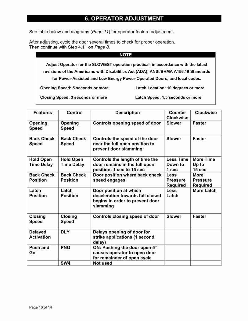
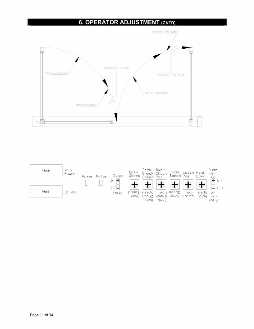
See table below and diagrams (Page 11) for operator feature adjustment. After adjusting, cycle the door several times to check for proper operation. Then continue with Step 4.11 on Page 8.
NOTE
Adjust Operator for the SLOWEST operation practical, in accordance with the latest
revisions of the Americans with Disabilities Act (ADA); ANSI/BHMA A156.19 Standards
for Power-Assisted and Low Energy Power-Operated Doors; and local codes.
Opening Speed: 5 seconds or more Latch Location: 10 degrees or more
Closing Speed: 3 seconds or more Latch Speed: 1.5 seconds or more
Features Control Description Counter Clockwise
Clockwise
Opening Speed
Opening Speed
Controls opening speed of door Slower Faster
Back Check Speed
Back Check Speed
Controls the speed of the door near the full open position to prevent door slamming
Slower Faster
Hold Open Time Delay
Hold Open Time Delay
Controls the length of time the door remains in the full open position: 1 sec to 15 sec
Less Time Down to 1 sec
More Time Up to 15 sec
Back Check Position
Back Check Position
Door position where back check speed engages
Less Pressure Required
More Pressure Required
Latch Position
Latch Position
Door position at which deceleration towards full closed begins in order to prevent door slamming
Less Latch
More Latch
Closing Speed
Closing Speed
Controls closing speed of door Slower Faster
Delayed Activation
DLY
Delays opening of door for strike applications (1 second delay)
Push and Go
PNG
ON: Pushing the door open 5° causes operator to open door for remainder of open cycle
SW4 Not used
6. OPERATOR ADJUSTMENT
Page 11 of 14
OpenOpenSpeedSpeed
Open OpenSpeed Speed
BackBackCheckCheckSpeedSpeed
Back BackCheck CheckSpeed Speed
Back BackCheck CheckPos Pos
BackBackCheckCheckPosPos
CloseCloseSpeedSpeed
Close CloseSpeed Speed
LatchLatchPosPos
Latch LatchPos Pos
Hold HoldOpen Open
HoldHoldOpenOpen
PushPush-n--n- Go Go
Push Push-n- -n- Go Go
DelayDelay
Delay Delay
OnOn
OffOff
OnOn
OffOff
MainMainPowerPower
12 VAC12 VAC
PowerPower MotorMotor
Fuse
Fuse
6. OPERATOR ADJUSTMENT (CNTD)
Page 12 of 14
7.1 Remove all tools, installation equipment and debris from the vicinity of the door. 7.2 MANDATORY: Install all Safety, Traffic Control and Instruction Labels onto the door, as required. Failure to do this will leave the INSTALLER LIABLE for any accidents that occur. 7.3 Give verbal instruction on how to properly operate the door to the owner or person in charge. 7.4 Give verbal instruction to the owner or person in charge on periodic inspection of the door for the following: • Occasional damage • Developing problems • Minor preventative maintenance 7.5 Provide the owner or person in charge with a contact name and phone number to call for future service and maintenance.
IMPORTANT
Be sure to install all Safety, Traffic Control and Instruction Labels
onto the door, as required
7. RELEASE FOR SERVICE
Page 13 of 14
8.1 Operation: 8.1.1 Sizing From start-up (Sizing), the door will activate via: • 1-Way Input (Main Act and Main Act). The first motion of the door will be towards the Door Open position. The speed during Sizing is automatic and cannot be set from a potentiometer. The door drives to full open and the system sets the open counter to full open. The door closes at Closing Speed. The system sets the closed counter to Full Closed when the latch goes up at the Closed position. The system calculates all other parameters required for normal operation based on the two values of Full Open and Full Closed. 8.1.2 Standard Operation Upon a legitimate activation signal, the door accelerates to opening speed while monitoring the current load on the drive output. If the current exceeds the specified level, the door will stop and close. The door travels at it’s set speed (based on the potentiometer setting) until it reaches the Back Check position, where it will decelerate to the Back Check Speed. The door will stop at the Hold Open position and remain there until an activation or the Hold Open Timer is cleared. The door then closes at its Closing Speed (based on the potentiometer setting) up to the latched position. If the Closing Speed is decreased by driving the motor in the open direction (a fixed setting), power is added to allow the spring to continue closing the door to the Full Closed position.
8. FALCON SOFTWARE
Page 14 of 14
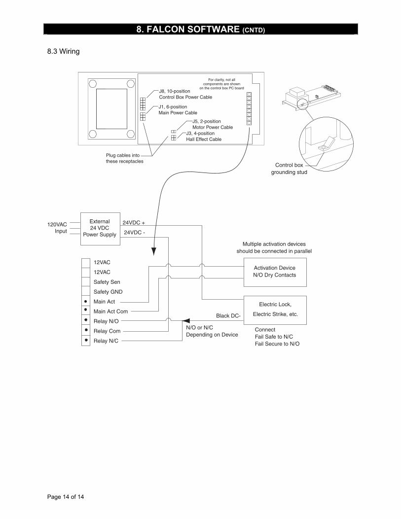
8.3 Wiring
24VDC +
24VDC -
Electric Lock,
Electric Strike, etc.
N/O or N/CDepending on Device
Black DC-
Activation DeviceN/O Dry Contacts
Multiple activation devicesshould be connected in parallel
Control boxgrounding stud
For clarity, not allcomponents are shown
on the control box PC boardJ8, 10-positionControl Box Power Cable
J1, 6-positionMain Power Cable
J5, 2-positionMotor Power Cable
J3, 4-positionHall Effect Cable
Plug cables intothese receptacles
External24 VDC
Power Supply
12VAC
12VAC
Safety Sen
Safety GND
Main Act
Main Act Com
Relay N/O
Relay Com
Relay N/C
120VACInput
ConnectFail Safe to N/CFail Secure to N/O
8. FALCON SOFTWARE (CNTD)