Embed Size (px)
Citation preview

FailuresinDry‐TypeTransformersforOffshore
Applications
Derek R Foster
10/15/2013
Copyright © Magnetics Design LLC 2013. All Rights Reserved.
Transformer / Inductor Specialists
Page 1 of 12
Failures in Dry-Type Transformers
for Offshore Applications
Abstract: this article focuses on failures involving only dry type transformers for offshore applications, from various perspectives: it addresses the most common causes of failures, the modes of failure, and recommendations for specification engineers and end users to reduce the possibility of failures, which will include the specification, operation and maintenance of dry type transformers , as well as procedures needed to be performed after a failure to minimize the disruption resulting from the failure.
Index Terms: offshore applications, dry-type transformers, cast coil, cast resin transformers, VPI transformer
Introduction
Compared with industrial and commercial applications, consequences of offshore transformer failures are much more serious, and are almost always associated, obviously, with additional costs, such as the cost of lost production and transformer replacement costs. Additionally, failures of transformers in offshore applications usually attract more serious safety issues, such as the possibility of fire, explosion, smoke and toxic fume emission.
Due to concerns regarding leaks from liquid filled transformers and the need to contain the leaking liquid, which may lead to a fire - a major concern for offshore applications - dry type transformers, either VPI (Vacuum Pressure Impregnated) or cast coil (cast resin) are the preferred option for offshore applications.
This article will examine the possible causes of failure, describe the modes of failure and provide recommendations to specifiers and end users, for reducing the occurrence of failures.
Causes of failure Below are listed a selection of common causes of failure specific to offshore and marine applications:
1. Environmental – effects of salt-laden atmosphere, moisture, chemical contamination
2. Vibration 3. Poor ventilation of transformer room or enclosure

Page 2 of 12
We will now consider the above in more detail.
Environmental.
Salt - Offshore equipment obviously spends its life operating in a salt laden atmosphere. This can cause corrosion of the copper or aluminum used for the conductors of the winding and the terminals, and also of the silicon steel core and the carbon steel used for the clamping structure.
Moisture - Moisture is the enemy of any electrical equipment, and the effects of moisture are obviously a much greater threat in offshore applications. Moisture reduces the dielectric properties of the insulation, which is especially problematic for the transformer coils. Surface moisture can lead to tracking over insulation surfaces, particularly in the case of medium voltage transformers.
Chemical contamination - Many different chemicals are used on drilling rigs and ships and these chemicals can be damaging to transformer insulation and conductors. For example, exhaust gases from engine driven generators may enter the transformer enclosure, where they can leave carbon deposits on coils which will lead to tracking and eventual damage to the transformer insulation system.
Transformers located outdoors or even in ventilated rooms, which draw cooling air from outside are especially vulnerable to the environmental effects listed above, as well as other forms of contamination, such as dust, which can result in a surface which is prone to tracking.
The results of salt laden air being drawn into the transformer enclosure

Page 3 of 12
Vibration
Since there is inherent vibration in drilling rigs and ships, precautions must be taken to prevent the vibration from causing damage to the transformer. The vibration can be of low frequency and can adversely affect both electrical and mechanical connnections. Loose electrical connections can lead to overheating or failure of these connections and possibly also of the transformer. Loose clamping bolts can result in the core laminations becoming loose and in coil displacement , either of which can result in mechanical damage to the structure of the transformer, and cause the transformer to become noisy and eventually lead to a failure.
Poor ventilation
Space is at a premium on drilling rigs and ships, so transformer rooms are often very small. This can lead to poor ventilation which can lead to overheating of the transformer, causing damage and loss of life to the insulation system. Transformer rooms need to be provided with sufficient air at the correct ambient temperature. This requirement is aggravated by the need to exclude the salt laden atmosphere from the transformer room, but if only air from outside is used, it is inevitable that this air will contain substances which are potentially damaging to transformers.
Other causes of failure are also possible but are not specific to offshore and marine applications, such as overloading, incorrect installation, manufacturing or material defects.
Modes of failure
Modes of failure usually fall into one of more of the following categories:
1. Insulation system failure in coils a. Sheet insulation – layer to layer ,turn to turn or winding to winding. b. Resin system
2. Conductor failure
a. Damage due to arcing following insulation failure b. Corrosion c. Heat damage d. Mechanical failure of conductors due to vibration
3. Mechanical damage

Page 4 of 12
Any of the failure modes above can result from the causes of failure listed earlier. Let us now examine each of these failure modes in more detail.
Insulation system failure – The construction and insulation of the coils may be regarded as the most critical item in a transformer, failure of any part of the insulation system will result in damage or catastrophic failure of the transformer. Insulation takes several forms:
Insulation system failure
Conductor failure - failure of electrical conductors, inside the coils is usually the result of a failure of the insulation system, which permits arcing between the turns or layers of a transformer winding, or even between windings. Less common is a failure due to overheating of the conductors resulting from an overload condition. Electrical conductors external to the coil can also fail for the same reasons as failure inside the coil, but an additional risk is failure due to connection problems, i.e. local heating at a bolted busbar joint, or a crimped connection. This type of failure can be the result of vibration, so it is essential that precautions are taken to reduce the possibility of vibration being transmitted to electrical connections. The necessary precautions will be discussed later in “How to reduce the possibility of failure”.
Mechanical damage - We have already mentioned damage to electrical conductors caused by vibration, but vibration can also result in failure of mechanical components such as the supports and clamping structure of the transformer.
1. Turn-to-turn. 2. Layer-to-layer. 3. Section-to-section. 4. Winding-to-winding. 5. Winding to ground.

Page 5 of 12
How to reduce the possibility of failure:
The aforesaid causes may contribute to failures separately or in combination with one another, and in many cases it is very difficult to determine which one is the direct cause of the failure. There are several precautions transformer users can take to reduce the possibility of failures, for example, provide a better environment for the transformer, such as an air-conditioned room, and share as much information as possible with the transformer manufacturer during preparation of the specification. Below are some specific recommendations which transformer users should consider, in order to reduce the possibility of failure for offshore applications:
Specify most suitable transformer, when all factors have been considered
1. Specify copper as the coil conductor material. Copper is capable of carrying a larger current per square inch of cross-section than aluminum, and it can dissipate heat more effectively. Transformers wound with copper have smaller coils and cores than transformers wound with aluminium for an equivalent transformer kVA rating and temperature rise, since the volume of copper required is less than the required volume of aluminum, and a smaller core is therefore required to accommodate the smaller coils. This gives transformers with copper windings two big advantages in offshore applications: they require less ventilation since the load losses generated in copper windings and the no-load losses generated in the core are considerably less than those in transformers with aluminum windings; they save space since the transformer is physically smaller and space is always a premium for offshore applications. Furthermore, the cost and weight saving of the coils achieved by the aluminum winding is somewhat offset by additional costs for core steel and insulation.
Copper is less susceptible to corrosion than aluminum. In fact, aluminum is not permitted by some certifying authorities for offshore applications, unless it is copper coated. Copper has a high thermal conductivity, so is poor at producing sparks, which can obviously be of benefit in the event of an electrical failure.
2. Specify cast coil insulation system
First, let us briefly introduce the differences between VPI transformers and Cast Coil transformers.

Page 6 of 12
For dry-type transformers, there are two basic choices for construction of the transformer: 1) Vacuum Pressure Impregnated (VPI) - Polyester resin or epoxy resin
technology of VPI, These transformers are generally referred to as open wound dry type transformers and employ the use of sheet insulation material, such as Nomex. Turn-to-turn insulation is often a polyester coating on the wire used for the winding or a tape fabricated from sheet material such as Nomex. The coils, or complete transformer, are finally dipped or vacuum pressure impregnated in an epoxy or polyester resin.
2) Cast coil (or cast resin) The winding method for cast coils is basically the same as that for VPI transformers, the difference being that the coils are placed in a mold after winding and resin is introduced under vacuum, after which the coil is placed in an oven for several hours for the resin to cure. The mold is then removed, leaving a coil with a smooth and hard resin surface which is thicker than the resin on a VPI coil. Two different technologies are used in construction of cast coil transformers, these are referred to as the “filled resin system” and “unfilled resin system”. Basically, the difference is that the “filled resin” system uses a combination of resin and quartz powder, while the “unfilled resin system” uses only pure resin.
VPI Transformer Cast Coil transformer

Page 7 of 12
Advantages of Cast Coil construction: 1) Impervious to moisture - since the casting process results in a completely
encapsulated and sealed winding, this renders the winding impervious to moisture, unlike a VPI transformer, where harsh environments and overloads can cause the thin coating of impregnating resin to deteriorate or crack, allowing moisture to enter the insulation system.
2) Mechanically stronger - the construction and materials of a cast coil transformer result in greater mechanical strength and resistance to the effects of long term vibration, due to the glass-fiber reinforcement used in the coil which in combination with the epoxy resin which provides a coil of very solid construction. In addition, the coil support blocks of most cast coil transformers are provided with shock absorbing pads or springs which effectively isolate the coils from the clamping structure, to reduce the possibility of vibration being transmitted into the coil, a feature which is rarely found on VPI transformers.
These construction features also result in increased short-circuit withstand capability compared with that of a VPI transformer.
Showing vibration damping pads under transformer (1), vibration pads under coil (2) and anti-tilt brackets (3)
3) Easy to clean - vacuum pressure impregnated coils tend to have a rough surface, and are often taped with a final layer of glass woven tape with an overlap which attracts dust very easily and can be difficult to clean. Blowing with an air line just drives the dust deeper into the insulation, so a vacuum cleaner should be used. This is much less of a problem with cast coil

Page 8 of 12
transformers whose coils have a smooth surface and may be easily wiped clean with a dry cloth to remove any dust or dirt which can produce a tracking path.
4) Partial discharge - in open wound, medium voltage transformers, partial discharge, resulting from small air voids in the windings, can damage the insulation system, due to electrical discharges in the voids which eats away the insulation and can result in failure of the transformer in a matter of weeks or months. With the complete resin impregnation of all parts of the coil, cast coil transformers are much less vulnerable to partial discharge.
A partial discharge test performed on the coils after manufacture will confirm that the level of partial discharge is less than that permitted by the IEEE Standard. However, while current standards permit a partial discharge level of 50pC in dry-type transformers, test values in cast coil transformers are typically in the 2-3pC range. For cast coil transformers, the risk of air voids in the winding still exists, but since for these transformers the partial discharge test is a routine test, the presence of voids will be detected at the factory, and in the event that the level of partial discharge is unacceptable, the coil will be replaced. For VPI transformers, the partial discharge test is a design test which will only be performed when requested by the customer.
Cast coil transformers, are typically a little larger and heavier than a VPI transformer of the same power rating and hence, more expensive - generally 20 to 25% higher in manufacturing cost than VPI transformers - but operate at lower temperature, which results in reduced load losses, and therefore reduced operating costs. So it is important to consider total cost of ownership, i.e. first cost, plus operating cost over the predicted lifetime of the transformer.
Coils using the unfilled resin system have the advantage that they are less prone to cracking of the resin, which has been known in coils using the filled resin system, especially when the resin and quartz powder have not been mixed properly.
3. Specify high quality core material
The use of a low loss grade of silicon steel, such as grade M3, together with “step lap” construction for the core, result in reduced no-load losses and reduced

Page 9 of 12
core weight. The reduced no-load losses in turn reduce the quantity of heat generated.
4. Specify appropriate enclosure Specify the correct degree of enclosure protection, at least NEMA 3R. The use of fans will assist ventilation, to ensure that the transformer does not overheat during periods of short term overload, causing damage and loss of life to the insulation system.
5. Specify some accessories - vibration dampers, heaters, fans, filters, Specify vibration damping, which will usually be in the form of rubber or cork pads. Determine if such pads are sufficient and suitable for the application, the use of spring dampers may be necessary in applications where vibration is a problem. Ventilation fans can provide at least a 33% increase in kVA rating of a transformer and as stated earlier this can provide an overload capability.
Transformers which are continuously energized, even with no load connected, generate heat in the silicon steel core, and this is usually sufficient to prevent the build-up of moisture. However, heaters installed inside the transformer enclosure will provide heat at times when the transformer is de-energized. In very dusty environments, the use of filters on enclosure ventilation grilles should be considered.
6. Specify Mechanically Strong construction, to withstand vibration and tilt requirement Transformers for offshore applications are subject to the requirements of certification bodies such as ABS, DNV, Lloyds etc. whose standards generally require the transformers to be suitable for use at a tilt angle of 22.5 degrees. This often requires the use of additional support bracing for the transformer, especially for larger transformers.

Page 10 of 12
Operation of transformers
It is essential to operate the transformer at all times within its nameplate ratings and to provide sufficient flow of cooling air to maintain the ambient temperature at the maximum permitted value – usually 45 or 50 deg.C
Regular maintenance
Read the manufacturers manual together with IEEE Standard C57.94, Recommended Practice for Installation, Application, Operation, and Maintenance of Dry-Type Distribution and Power Transformers, for recommendations regarding maintenance. Keeping the transformer coils clean is of utmost importance. Dust, dirt and other forms of contamination result in a reduction in the dielectric strength of the transformer, and may lead to tracking or arcing. Dust should preferably be removed with the use of a vacuum cleaner, to suck the dust out, instead of blowing, which can drive the dust into the insulation of the coils, instead of removing it. All nuts and bolts should be regularly checked for tightness, and if tightening is required, the manufacturers’ recommendations regarding torque values should be observed. This is particularly important for bolted electrical connections, to prevent overheating of the connections.
The period of time between maintenance procedures will vary, depending upon site conditions. Generally, every twelve months is usually sufficient, but it is recommended that the transformer be inspected every three months during the first year of operation, in order to determine the appropriate interval between maintenance procedures.
Reduce the possibility of contamination into the transformer
When transformers are installed in ventilated enclosures, the ventilation grilles should be kept free of dust and other obstructions. If filters are used, they should be cleaned or replaced at regular intervals and when filters are installed after the transformer has been placed in service, the manufacturer should be consulted for recommendations regarding cooling, since the filters reduce air flow through the enclosure.
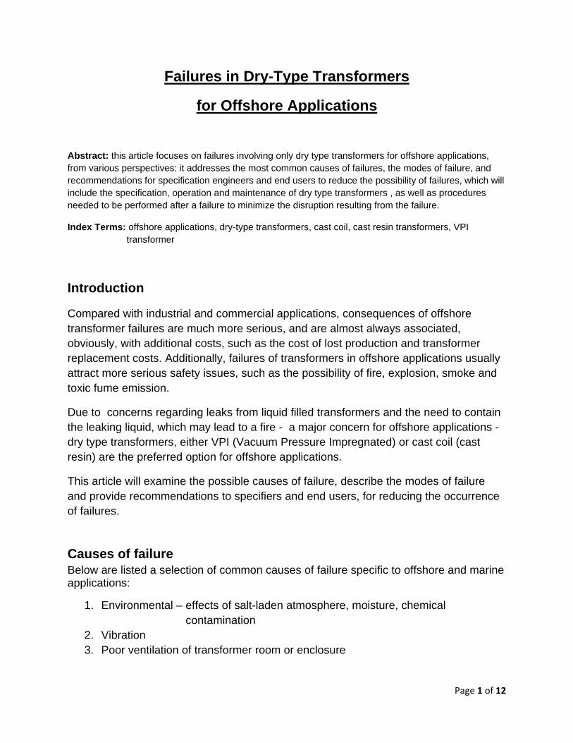
The transformer should be protected from exhaust gases being emitted by other equipment, such as engine driven generators. These gases should not be allowed to enter the enclosure. The coil surfaces can quickly be contaminated by carbon deposits, which will lead to tracking or arcing.
Page 11 of 12
The effect of generator exhaust gases entering the transformer enclosure from the deck below
If the transformer is out of service at any time, heaters inside the enclosure should be energized to prevent the build-up of moisture on the coils.
After a failure
The failure of a transformer should automatically trigger the protective devices which will disconnect power from the transformer. If there is a fire resulting from the failure, this will usually stop within a few minutes of power being removed, since the materials used in the construction of the transformer are generally self-extinguishing.
There is often more than one transformer in a transformer room, so any other transformers nearby should be inspected for damage, either secondary fire damage or the presence of powder used to extinguish any fire in the failed transformer. This powder should be removed with a vacuum cleaner, not blown with an air line.
The failed transformer should be inspected and the cause of failure determined in order to avoid further failures after repair or replacement of the failed transformer.
Before re-energizing any other transformers on the same power supply, it is recommended that these transformers be subjected to basic tests, as detailed in IEEE Standard C57.94, Recommended Practice for Installation, Application, Operation, and Maintenance of Dry-Type Distribution and Power Transformers.

Page 12 of 12
Conclusions
As stated earlier, dry-type transformers are the preferred option for offshore and marine applications, but there are several factors to take into account during the specification process to ensure that the most suitable transformer has been selected. Careful specification and regular inspections will much reduce the likelihood of failure, which can be disruptive and very costly.
About the Author: Derek Foster was born and educated in England. He entered the transformer industry in 1974 and has extensive experience in the design, manufacture and application of specialty transformers and inductors in Europe, US and China. Derek Foster is currently Chairman of the working group for ANSI/IEEE Standard C57.12.91, IEEE Standard Test Code for Dry-Type Distribution and Power Transformers. Derek Foster is the president of Magnetics Design LLC. This article only represent the writer’s own opinion, and use of this article is wholly voluntary. The writer disclaims liability for any personal injury, property or other damage, of any nature whatsoever, whether special, indirect, consequential, or compensatory, directly or indirectly resulting from the publication, use of, or reliance upon this article.
All Rights Reserved. Any unauthorized reprint or use of this material is prohibited. No part of this article may be reproduced or transmitted in any form or by any means, electronic or mechanical, including photocopying, recording, or by any information storage and retrieval system without express written permission from the author.
www.magneticsdesigns.com