Embed Size (px)
Citation preview
LTE Radio Access, Rel. RL40, Operating Documentation, Issue 01
Fault Management
DN0944028
Issue 03Approval Date 2011-04-15
Confidential
Nokia Siemens Networks is continually striving to reduce the adverse environmental effects of its products and services. We would like to encourage you as our customers and users to join us in working towards a cleaner, safer environment. Please recycle product packaging and follow the recommendations for power use and proper disposal of our products and their compo-nents.
If you should have questions regarding our Environmental Policy or any of the environmental services we offer, please contact us at Nokia Siemens Networks for any additional information.
2 DN0944028
Fault Management
Id:0900d80580966ea6Confidential
The information in this document is subject to change without notice and describes only the product defined in the introduction of this documentation. This documentation is intended for the use of Nokia Siemens Networks customers only for the purposes of the agreement under which the document is submitted, and no part of it may be used, reproduced, modified or transmitted in any form or means without the prior written permission of Nokia Siemens Networks. The documentation has been prepared to be used by professional and properly trained personnel, and the customer assumes full responsibility when using it. Nokia Siemens Networks welcomes customer comments as part of the process of continuous development and improvement of the documentation.
The information or statements given in this documentation concerning the suitability, capacity, or performance of the mentioned hardware or software products are given "as is" and all liability arising in connection with such hardware or software products shall be defined conclusively and finally in a separate agreement between Nokia Siemens Networks and the customer. However, Nokia Siemens Networks has made all reasonable efforts to ensure that the instructions contained in the document are adequate and free of material errors and omissions. Nokia Siemens Networks will, if deemed necessary by Nokia Siemens Networks, explain issues which may not be covered by the document.
Nokia Siemens Networks will correct errors in this documentation as soon as possible. IN NO EVENT WILL Nokia Siemens Networks BE LIABLE FOR ERRORS IN THIS DOCUMENTA-TION OR FOR ANY DAMAGES, INCLUDING BUT NOT LIMITED TO SPECIAL, DIRECT, INDI-RECT, INCIDENTAL OR CONSEQUENTIAL OR ANY LOSSES, SUCH AS BUT NOT LIMITED TO LOSS OF PROFIT, REVENUE, BUSINESS INTERRUPTION, BUSINESS OPPORTUNITY OR DATA,THAT MAY ARISE FROM THE USE OF THIS DOCUMENT OR THE INFORMATION IN IT.
This documentation and the product it describes are considered protected by copyrights and other intellectual property rights according to the applicable laws.
The wave logo is a trademark of Nokia Siemens Networks Oy. Nokia is a registered trademark of Nokia Corporation. Siemens is a registered trademark of Siemens AG.
Other product names mentioned in this document may be trademarks of their respective owners, and they are mentioned for identification purposes only.
Copyright © Nokia Siemens Networks 2011. All rights reserved
f Important Notice on Product SafetyThis product may present safety risks due to laser, electricity, heat, and other sources of danger.
Only trained and qualified personnel may install, operate, maintain or otherwise handle this product and only after having carefully read the safety information applicable to this product.
The safety information is provided in the Safety Information section in the “Legal, Safety and Environmental Information” part of this document or documentation set.
The same text in German:
f Wichtiger Hinweis zur Produktsicherheit Von diesem Produkt können Gefahren durch Laser, Elektrizität, Hitzeentwicklung oder andere Gefahrenquellen ausgehen.
Installation, Betrieb, Wartung und sonstige Handhabung des Produktes darf nur durch geschultes und qualifiziertes Personal unter Beachtung der anwendbaren Sicherheits-anforderungen erfolgen.
Die Sicherheitsanforderungen finden Sie unter „Sicherheitshinweise“ im Teil „Legal, Safety and Environmental Information“ dieses Dokuments oder dieses Dokumentations-satzes.
DN0944028 3
Fault Management
Id:0900d80580966ea6Confidential
Table of contentsThis document has 19 pages.
Summary of changes . . . . . . . . . . . . . . . . . . . . . . . . . . . . . . . . . . . . . . . . 6
1 Introduction to fault management . . . . . . . . . . . . . . . . . . . . . . . . . . . . . . 7
2 Fault management features . . . . . . . . . . . . . . . . . . . . . . . . . . . . . . . . . . . 82.1 Functional overview of LTE656: Fault Management . . . . . . . . . . . . . . . . 82.2 Functional overview of LTE447: SW support for RF sharing GSM-LTE . 82.3 Functional overview of LTE424: Automatic interface alarm correlation . . 8
3 Architecture of fault management . . . . . . . . . . . . . . . . . . . . . . . . . . . . . . 93.1 User . . . . . . . . . . . . . . . . . . . . . . . . . . . . . . . . . . . . . . . . . . . . . . . . . . . . . 93.2 NetAct . . . . . . . . . . . . . . . . . . . . . . . . . . . . . . . . . . . . . . . . . . . . . . . . . . . 93.3 eNB . . . . . . . . . . . . . . . . . . . . . . . . . . . . . . . . . . . . . . . . . . . . . . . . . . . . 103.4 BTS Site Manager . . . . . . . . . . . . . . . . . . . . . . . . . . . . . . . . . . . . . . . . . 103.5 iOMS . . . . . . . . . . . . . . . . . . . . . . . . . . . . . . . . . . . . . . . . . . . . . . . . . . . 10
4 Functional description for fault management . . . . . . . . . . . . . . . . . . . . . 114.1 Fault management principles. . . . . . . . . . . . . . . . . . . . . . . . . . . . . . . . . 114.1.1 NetAct . . . . . . . . . . . . . . . . . . . . . . . . . . . . . . . . . . . . . . . . . . . . . . . . . . 114.1.2 eNB . . . . . . . . . . . . . . . . . . . . . . . . . . . . . . . . . . . . . . . . . . . . . . . . . . . . 124.1.2.1 Critical alarms . . . . . . . . . . . . . . . . . . . . . . . . . . . . . . . . . . . . . . . . . . . . 124.1.2.2 Clearing alarms . . . . . . . . . . . . . . . . . . . . . . . . . . . . . . . . . . . . . . . . . . . 124.1.2.3 Alarms per fault . . . . . . . . . . . . . . . . . . . . . . . . . . . . . . . . . . . . . . . . . . . 134.1.2.4 Alarm management . . . . . . . . . . . . . . . . . . . . . . . . . . . . . . . . . . . . . . . . 134.2 Suppress (block) toggling fault. . . . . . . . . . . . . . . . . . . . . . . . . . . . . . . . 134.2.1 Suppress (block) toggling fault functionality. . . . . . . . . . . . . . . . . . . . . . 134.2.2 User interface . . . . . . . . . . . . . . . . . . . . . . . . . . . . . . . . . . . . . . . . . . . . 144.3 Fault management related to LTE 447: SW support for RF sharing GSM -
LTE . . . . . . . . . . . . . . . . . . . . . . . . . . . . . . . . . . . . . . . . . . . . . . . . . . . . 164.3.1 RF sharing configurations . . . . . . . . . . . . . . . . . . . . . . . . . . . . . . . . . . . 16
5 Management data for fault management . . . . . . . . . . . . . . . . . . . . . . . . 175.1 Alarms . . . . . . . . . . . . . . . . . . . . . . . . . . . . . . . . . . . . . . . . . . . . . . . . . . 175.2 Measurements and counters . . . . . . . . . . . . . . . . . . . . . . . . . . . . . . . . . 175.3 Key performance indicators . . . . . . . . . . . . . . . . . . . . . . . . . . . . . . . . . . 175.4 Parameters . . . . . . . . . . . . . . . . . . . . . . . . . . . . . . . . . . . . . . . . . . . . . . 17
6 Operating tasks related to fault management . . . . . . . . . . . . . . . . . . . . 186.1 Alarm monitoring with BTSSM . . . . . . . . . . . . . . . . . . . . . . . . . . . . . . . . 186.2 Alarm monitoring with NetAct. . . . . . . . . . . . . . . . . . . . . . . . . . . . . . . . . 18
4 DN0944028
Fault Management
Id:0900d80580966ea6Confidential
List of figuresFigure 1 LTE alarm system architecture . . . . . . . . . . . . . . . . . . . . . . . . . . . . . . . . . 9Figure 2 Suppress (block) toggling faults . . . . . . . . . . . . . . . . . . . . . . . . . . . . . . . 14Figure 3 Block Toggling Fault Feature in the Fault View . . . . . . . . . . . . . . . . . . . 14Figure 4 Block Toggling Fault Dialog . . . . . . . . . . . . . . . . . . . . . . . . . . . . . . . . . . 15Figure 5 Filter definitions (example) . . . . . . . . . . . . . . . . . . . . . . . . . . . . . . . . . . . 16
DN0944028 5
Fault Management
Id:0900d80580966ea6Confidential
List of tablesTable 1 Fault management features . . . . . . . . . . . . . . . . . . . . . . . . . . . . . . . . . . 8Table 2 Alarms related to LTE656: LTE Fault Management . . . . . . . . . . . . . . . 17Table 3 Parameters related to LTE656: LTE Fault Management . . . . . . . . . . . 17
6 DN0944028
Fault Management
Id:0900d805808c8ccaConfidential
Summary of changes
Summary of changesChanges between document issues are cumulative. Therefore, the latest document issue contains all changes made to previous issues.
Changes between issues 02 (2010-12-15, RL20) and 03 (2011-04-18, RL30) 2 Fault management features
• LTE424: Automatic interface alarm correlation added
4 Functional description for fault management
• section Automatic interface alarm correlation added
Changes between issues 01B (2010-05-31, RL10) and 02 (2010-12-15, RL20)2 Fault management features
• LTE 447: SW support for RF sharing GSM - LTE added
4 Functional description for fault management
• section Fault management related to LTE 447: SW support for RF sharing GSM - LTE added
6 Operating tasks related to fault management
• section Alarm Monitoring with NetAct added
Information on alarms, counters, KPIs, and parameters moved to section 5 Management data for fault management.
Changes between issues 01A (2010-02-28) and 01B (2010-05-31)4 Functional description for fault management
• section Suppress (block) toggling fault added • section User interface added
5 Management data for fault management
• table Parameters related to LTE656: LTE Fault Management added
DN0944028 7
Fault Management Introduction to fault management
Id:0900d80580966e96Confidential
1 Introduction to fault managementThe Fault Management (FM) functionality allows fault monitoring in the LTE RAN network. Faults are presented as alarm notifications that have certain basic character-istics in each network element for identifying and correcting the fault. Each network element keeps track of its own alarm situation and provides interfaces for viewing the alarms or managing the network element alarm system. These interfaces are provided to both local users via local user interfaces and to NetAct.
Each network element type in the LTE RAN system has its own set of alarms that it can generate. Each alarm is documented separately. In this way the user gets the following information about an alarm:
• the meaning of the alarm • description of the additional information related to the alarm • instructions on how to analyze and correct the fault, if the fault correction requires
user actions.
For details on alarms, see Flexi Multiradio BTS LTE Faults, Flexi Multiradio BTS LTE Alarms, and LTE iOMS Alarms and Troubleshooting.
The main functions in the FM area on the system-level are:
• alarm events • alarm upload
Alarm events are used to keep the network management system up-to-date about the alarm situation in the lower-level network elements. These events are sent from the network elements as they appear and the events are buffered to prevent the alarm loss in an alarm event reporting congestion or a short network break situation. Alarm upload functionality provides a solution for synchronizing the alarm situation between the systems (if necessary).
NetAct monitors the alarm flow from the eNB by using the heartbeat alarms, generated by the eNB with defined intervals. This heartbeat interval can be modified if needed.
Alarm events are collected in the alarm history which is available for troubleshooting and network analyzing purposes. NetAct collects the RAN-level alarm history and the eNB provides local user interfaces for the network element-specific alarm history data. For further information on different alarm history viewing tools, see the product documenta-tion of relevant network elements.
8 DN0944028
Fault Management
Id:0900d8058086d173Confidential
Fault management features
2 Fault management featuresTable 1 shows features related to the fault management area.
2.1 Functional overview of LTE656: Fault ManagementAlarms are reported to the management systems, including the cause of the service loss. The alarms themselves are supplemented with the alarm manual pages to describe the conditions in more details. The fault detection also leads (if needed) to automatic recovery actions. The eNB alarm system gathers alarm reports from the appli-cation software in the eNB and reports them to the NetAct. NetAct graphical user inter-face provides a view of active alarms and relevant reports as an alarm history and it allows the operator to modify the alarm parameters. Alarm monitoring is also possible with the BTS Site Manager.
2.2 Functional overview of LTE447: SW support for RF sharing GSM-LTEFlexi Multiradio RF Module operates in concurrent GSM and LTE mode. This means that one Flexi Multiradio RF Module transmits both GSM/EDGE RF carrier(s) and LTE RF carrier signals at the same 3GPP frequency band. Flexi EDGE System Module operates in GSM/EDGE SW mode and Flexi Multimode System Module in LTE SW mode. Both are connected to the one and same Flexi Multiradio RF Module.
This feature includes the necessary adaptations in O&M (including fault management) to be considered for support of the concurrent mode for GSM / LTE with RF sharing.
2.3 Functional overview of LTE424: Automatic interface alarm correlationThis feature minimizes the number of alarms reported in NetAct. In case of problems with central interfaces (X2, S1), the operator receives a dedicated correlated alarm instead of many uncorrelated alarms. For more information, see LTE424: Automatic interface alarm correlation.
Feature Release
LTE656: Fault management RL10
LTE447: SW support for RF sharing GSM-LTE RL20
LTE424: Automatic interface alarm correlation RL30
Table 1 Fault management features

DN0944028 9
Fault Management Architecture of fault management
Id:0900d8058083cc3aConfidential
3 Architecture of fault management
Figure 1 LTE alarm system architecture
3.1 UserThe fault management functionality itself does not require user actions, because it is always active in the background, and the alarms are presented to the user when they occur. The user can, however, trigger the alarm upload from a certain network element, if it is suspected that the alarm situation is not up-to-date.
3.2 NetActNetAct tools provide a real-time view of network alarms. Alarms are forwarded from the eNB to the NetAct, so the user has continuous access to the most recent alarm situation in the LTE RAN network. The user can trigger the alarm upload from the network element manually if needed, by using NetAct tools.
10 DN0944028
Fault Management
Id:0900d8058083cc3aConfidential
Architecture of fault management
3.3 eNBThe eNB alarm system collects the alarms from the eNB and its transport module. The alarms are buffered in the eNB and sent to the NetAct alarm system or mediator one by one via the eNB O&M interface. The alarm upload is started on the eNB request when needed.The eNB local UI provides a view to active alarms of a single eNB.
3.4 BTS Site ManagerWith the BTS Site Manager, the alarms can be managed and viewed locally for a single eNB.
3.5 iOMSThe iOMS acts as a mediator between eNBs and NetAct. It receives the data from several eNBs and forwards them to NetAct. It also provides storage for the FM data.

DN0944028 11
Fault Management Functional description for fault management
Id:0900d80580966e98Confidential
4 Functional description for fault management
4.1 Fault management principlesThe fault management system helps the operator to monitor the network. A decrease in the service-level is reported to the operator (including the cause of the service loss). With the network monitoring tools, the user gets the information to start recovery actions.
The complete functionality of the eNB is supervised via alarms. The eNB detects faults, localizes them, generates Failure Event Reports (FER) and sends them to NetAct. Also via the BTS Site Manager the alarms can be managed locally for a single eNB. The alarm is generated immediately when a fault situation occurs (including the cause of the service loss). The alarms themselves are supplemented with the alarm manual pages to describe the conditions in more details.
4.1.1 NetActNetAct provides a graphical user interface to view the active alarms with the related reports as well as the alarm history. The operator to modify alarm parameters, for example, the alarm severity.
The report gives details on how the fault affects the services of logical objects in the network and, if available, the physical unit that caused the service loss. The report contains also the alarm number, which is an entry to the alarm reference manual, and an alarm text which explains briefly the fault and gives information on the severity level and time.
The alarm is generated immediately when a fault situation occurs. NetAct updates the alarm situation automatically. The alarm information provided via the NetAct northbound interface is assembled according to ITU X.733 and 3GPP TS 32.111 and comprises:
• the alarm type (for example communications alarm, resource shortage, equipment alarm, quality of service alarm, and so on)
• the emitting object • the severity (critical, major, minor) • probable cause • specific problem • notification ID • alarm time • additional text
This information is valuable for the operator in that it is easier to track down the source of the alarm and eliminate the trouble. To cope with the strong demand of the operators, that alarms contain information about the necessary maintenance measures resulting from the alarm, or that this maintenance information can be retrieved offline (for example, by means of the probable cause). Then the eNB provides maintenance infor-mation wherever possible. Within the eNB (and NetAct as well), it is possible to filter alarms based on criteria's like alarm Type, emitting object, and perceived Severity. Filtered alarms are not forwarded towards the NetAct monitoring system.
Automatic interface alarm correlationWith the introduction of LTE424: Automatic interface alarm correlation, the number of alarms reported in NetAct can be reduced. Alarms caused by problems with S1/X2 inter-
12 DN0944028
Fault Management
Id:0900d80580966e98Confidential
Functional description for fault management
faces, GTPU/SCTP path failure, or SCTP endpoint failure are correlated and only a ded-icated interface-specific alarm is raised. The Flexi Multiradio BTS provides the correlation information in the alarm message. The user can check all the correlated alarms in the NetAct alarm correlator view.
4.1.2 eNBThe eNB is able to identify each generated alarm which is also filtered by the toggling alarm suppression.
It has a mechanism to keep track of the state of detected individual faults. It knows the active alarm situation and which are the current faults and related alarms. The severity level classifies the alarms according to their priorities and effects on services. The assignments of severity levels within the eNB are fixed and cannot be modified from NetAct or the BTS Site Manager.
After the eNB reset and the connection establishment between the eNB and the BTSSM, an automatic alarm upload is initiated to ensure that the alarm situation in the BTSSM is up-to-date. The local alarm GUI data is updated in real-time (every time when a new alarm occurs). After a connection interruption between the eNB and the Site Manager, the eNB requests an alarm upload if the alarm situation in the eNB has changed during the connection interruption.
It is possible to define external alarms in the eNB.
4.1.2.1 Critical alarmsCritical alarms require immediate actions from the maintenance personnel; all other alarms require actions during working hours. Handling of the alarms is carried out at dif-ferent levels of the alarm system to simplify the pre-processing of the fault observations and to reduce the load on the whole alarm system.
Alarms with severity warning are not treated as permanent faults. Hence, these alarms are not stored as active alarms in the eNB and are also not aligned to the NetAct when an alarm alignment is requested by the management system.
The eNB maintains the currently active alarms. It will send these alarms to NetAct on request, independently of autonomous alarm reporting. (The definition of active alarm: an alarm event reported for a faulty condition with the severity minor, major or critical, which has not been already cleared by the eNB).
One and the same alarm is not generated or sent more than once before it is cleared.
4.1.2.2 Clearing alarmsAs soon as a fault condition is not active any more, the eNB sends a clearing alarm noti-fication. Exceptions for automatic alarm clearing are the security alarms. This kind of alarms need to be cleared by the operator personnel also if the fault condition doesn't exist any longer. The emitted alarm clearing notification unambiguously identifies the corresponding original alarm(s). After the eNB restart, the alarm situation is verified and only active alarms are reported, all others are automatically cleared.

DN0944028 13
Fault Management Functional description for fault management
Id:0900d80580966e98Confidential
4.1.2.3 Alarms per faultGeneration of more than one alarm per fault, that is, the generation of induced alarms, is avoided. However, exceptions may appear in the in the following two cases:
a) Alarming of key services with high importance for the operatorb) The primary fault is outside the scope of the NE and the current NE has no knowl-
edge about it.
An example of a key service is a cell that - as a consequence of some board failures - goes out of service. An alarm is generated for the board failure, and induced alarms are generated for the affected cells. Each alarm has a unique notification identifier. The sup-pression of toggling alarms is supported. The configurable toggling conditions can be browsed, added and modified via BTSSM or NetAct
4.1.2.4 Alarm managementAlarms for both transport modules and antenna lines are supported:
• The transport module alarms are collected in the eNB alarm system and reported to the management system as radio eNB alarms. The transport module alarms are also included in the eNB alarm upload.
• The antenna line fault management is supported by including VSWR alarming.
4.2 Suppress (block) toggling fault
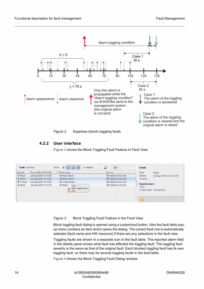
4.2.1 Suppress (block) toggling fault functionalityIn order to reduce the amount of alarms in the BTS to the really important ones and in order to prevent the system from alarms which fill the alarm buffers but do not provide further important information, alarms which are raised and cleared in a short period of time and which do not give further information for fault analysis and fault localization are suppressed by means of a special algorithm. This algorithm detects toggling alarms as such and suppress the toggling alarm notifications after a specified time. If the same alarm is raised by the same MO "x" times within "y" seconds, the system enters the alarm toggling condition for this alarm in this related MO. During the alarm toggling con-dition, the single alarm clearance messages and alarm notifications are suppressed. The alarm toggling condition can be left in two different cases:
Case 1: If the alarm is not present for "z" seconds after the alarm toggling condition is left, an alarm clearance message, which indicates the end of the alarm toggling condi-tion, is sent.
Case 2: If the alarm in question becomes a stable state for the duration of "z" seconds, then the alarm toggling condition is left (see also case 1) and the concerning alarm message of the single alarm is sent to the management system.
Figure 2 shows the suppress (block) toggling faults.
14 DN0944028
Fault Management
Id:0900d80580966e98Confidential
Functional description for fault management
Figure 2 Suppress (block) toggling faults
4.2.2 User interfaceFigure 3 shows the Block Toggling Fault Feature in Fault View
Figure 3 Block Toggling Fault Feature in the Fault View
Block toggling fault dialog is opened using a customized button. Also the fault table pop-up menu contains an item which opens the dialog. The correct fault row is automatically selected (fault name and HW resource) if there are any selections in the fault view.
Toggling faults are shown in a separate icon in the fault table. The reported alarm field in the details panel shows what fault has affected the toggling fault. The toggling fault severity is the same as that of the original fault. Each blocked toggling fault has its own toggling fault, so there may be several toggling faults in the fault table.
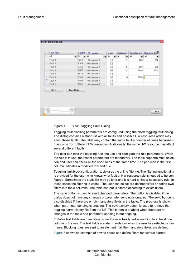
Figure 4 shows the Block Toggling Fault Dialog window
DN0944028 15
Fault Management Functional description for fault management
Id:0900d80580966e98Confidential
Figure 4 Block Toggling Fault Dialog
Toggling fault blocking parameters are configured using the block toggling fault dialog. The dialog contains a static list with all faults and possible HW resources which may affect those faults. The table may contain the same fault a number of times because it may come from different HW resources. Additionally, the same HW resource may affect several different faults.
The user can take the blocking rule into use and configure the rule parameters. When the rule is in use, the rest of parameters are mandatory. The table supports multi-selec-tion and user can check all the used rules at the same time. The pen icon in the first column indicates a modified row and rule.
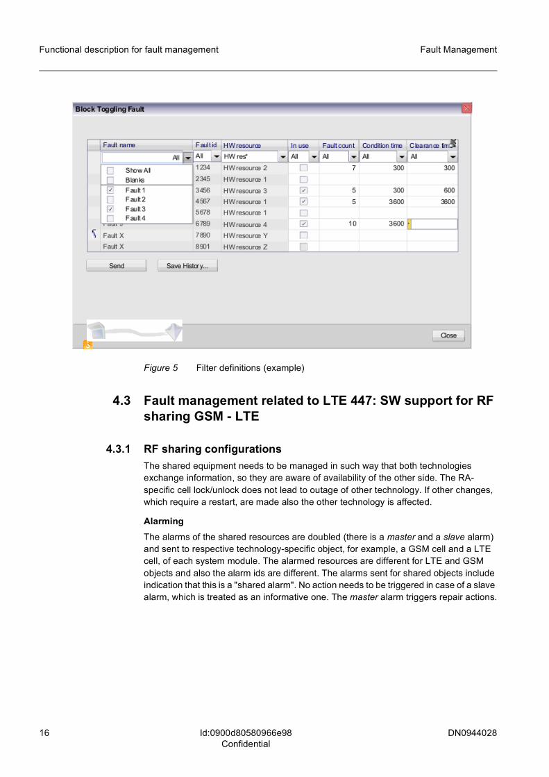
Toggling fault block configuration table uses the online filtering. The filtering functionality is provided for the user, who knows what fault or HW resource rule is needed to be con-figured. Sometimes the static list may be long and it is hard to find a necessary rule. In those cases the filtering is useful. The user can select pre-defined filters or define own filters into table columns. The table content is filtered according to exists filters.
The send button is used to send changed parameters. The button is disabled if the dialog does not have any changes or parameter sending is ongoing. The send button is also disabled if there are empty mandatory fields in the table. The progress is shown when parameter sending is ongoing. The save history button is used to retrieve the toggling alarm history file from the NE. This button is enabled when there are no changes in the table and parameter sending is not ongoing.
Editable text fields are mandatory when the user has typed something to at least one column in the row. The text fields are also mandatory when the user has selected a row in use. Blocking rules are sent to an element if all the mandatory fields are defined.
Figure 5 shows an example of how to check and define filters for several alarms.
16 DN0944028
Fault Management
Id:0900d80580966e98Confidential
Functional description for fault management
Figure 5 Filter definitions (example)
4.3 Fault management related to LTE 447: SW support for RF sharing GSM - LTE
4.3.1 RF sharing configurations The shared equipment needs to be managed in such way that both technologies exchange information, so they are aware of availability of the other side. The RA- specific cell lock/unlock does not lead to outage of other technology. If other changes, which require a restart, are made also the other technology is affected.
AlarmingThe alarms of the shared resources are doubled (there is a master and a slave alarm) and sent to respective technology-specific object, for example, a GSM cell and a LTE cell, of each system module. The alarmed resources are different for LTE and GSM objects and also the alarm ids are different. The alarms sent for shared objects include indication that this is a "shared alarm". No action needs to be triggered in case of a slave alarm, which is treated as an informative one. The master alarm triggers repair actions.
DN0944028 17
Fault Management Management data for fault management
Id:0900d80580966e9aConfidential
5 Management data for fault managementThis section lists the management data related to the fault management area.
5.1 AlarmsTable 2 shows alarms related to LTE656: LTE Fault Management.
For information on alarms related to LTE424: Automatic interface alarm correlation, see LTE424: Automatic interface alarm correlation.
5.2 Measurements and countersThe are no measurements and counters related to fault management.
5.3 Key performance indicatorsThe are no key performance indicators related to fault management.
5.4 ParametersTable 3 shows parameters related to LTE656: LTE Fault Management.
Alarm ID Alarm name
4026 Toggling: <Fault name>
Table 2 Alarms related to LTE656: LTE Fault Management
Full name Abbreviated name Managed object
Toggling alarm suppression list (structure) alToggSuppList BTSSCL
Toggling alarm amount alToggAmount BTSSCL
Toggling clearance time alToggClearence-Time
BTSSCL
Toggling alarm condition time alToggConditonTime BTSSCL
BTS Fault name faultName BTSSCL
Suppression of toggling alarms in use inUse BTSSCL
Table 3 Parameters related to LTE656: LTE Fault Management
18 DN0944028
Fault Management
Id:0900d8058086d22eConfidential
Operating tasks related to fault management
6 Operating tasks related to fault management
6.1 Alarm monitoring with BTSSMActors:The operator using BTS Site Manager tools for monitoring BTS.
FrequencySeveral times per day.
PreconditionsThe DCN connection between the BTS and BTSSM is open. The BTS management plane is operational. The connection to BTS is established and the BTSSM is opera-tional.
Description
1. The user starts the BTSSM.2. The alarm situation is aligned between the BTS and the BTSSM.3. The user is able to see the alarm situation of the eNB and that the BTSSM is con-
nected to it with the default filtering criteria. The alarm status is updated from eNB to BTS SM without user actions.
4. The user can sort and select the alarm, view information modules, and view the sorting order in the BTSSM.
5. The user is able to acquire and see the additional alarm information from the alarm manual page.
6. The user is able to view the alarm history (BTSSM) from the connection establish-ment.
7. The BTS SM connection can be released by the user.
6.2 Alarm monitoring with NetActActors:The operator using NetAct tools for monitoring network.
FrequencySeveral times per day.
PreconditionsThe DCN connection between the eNB and NetAct is open. The NE management plane is operational. The connection established to eNB and NetAct is operational.
Description
1. The eNB detects an alarm or cancels an existing alarm and notifies the eNB alarm system. The eNB alarm system stores the alarm.
2. The eNB sends the updated alarm/cancel to the O&M mediator (iOMS) with the Alarm Observation message.
3. The iOMS receives the alarm information and acknowledges the event back to eNB.4. iOMS updates the alarm/cancel information in the database. From the database the
information is updated to iOMS applications.
DN0944028 19
Fault Management Operating tasks related to fault management
Id:0900d8058086d22eConfidential
5. iOMS sends the alarm/cancel information to NetAct with the AlarmEvent message.
6. NetAct receives the alarm/cancel information and updates the FM database.7. NetAct updates the new alarm/cancel information in the NetAct alarm buffer.8. NetAct informs iOMS about the successful transfer.9. NetAct updates the new alarm/cancel information in NetAct applications that use
alarm information. The user is able to receive additional information about alarms from the alarm manual.


