Embed Size (px)
Citation preview

FactoryCAD Tutorial 2
July 10, 2003

Proprietary Rights Notices
This software and related documentation are proprietary to Electronic Data Systems Corporation.
© 2003 Electronic Data Systems Corporation. All Rights Reserved
LIMITATIONS TO U.S. GOVERNMENT RIGHTS. UNPUBLISHED - RIGHTS RESERVED UNDER THE COPYRIGHT LAWS OF THE UNITED STATES. This computer software and related computer software documentation have been developed exclusively at private expense and are provided subject to the following rights: If this computer software and computer software documentation qualify as "commercial items" (as that term is defined in FAR 2.101), their use, duplication or disclosure by the U.S. Government is subject to the protections and restrictions as set forth in the Electronic Data Systems Corporation commercial license for the software and/or documentation, as prescribed in FAR 12.212 and FAR 27.405(b)(2)(i) (for civilian agencies) and in DFARS 227.7202-1(a) and DFARS 227.7202-3(a) (for the Department of Defense), or any successor or similar regulation, as applicable or as amended from time to time. If this computer software and computer documentation do not qualify as "commercial items," then they are "restricted computer software" and are provided with "restrictive rights," and their use, duplication or disclosure by the U.S. Government is subject to the protections and restrictions as set forth in FAR 27.404(b) and FAR 52-227-14 (for civilian agencies), and DFARS 227.7203-5(c) and DFARS 252.227-7014 (for the Department of Defense), or any successor or similar regulation, as applicable or as amended from time to time. Electronic Data Systems Corporation, 5400 Legacy Drive, Plano, Texas 75024-3199.
EDS is a registered trademark of Electronic Data Systems Corporation. All other company names, trademarks or registered trademarks referenced herein belong to their respective holders.
2 FactoryCAD Tutorial 2

FactoryCAD Tutorial 2 This tutorial is intended to fulfill the following functions:
• Introduce FactoryCAD and its capabilities
• Train beginners in representative tasks
• Instruct beginners and users familiar with earlier versions in key features of FactoryCAD
• Provide quick look-up of representative step-by-step procedures or facts about FactoryCAD for casual users
• Elaborate on specific features of FactoryCAD directed toward factory layout design inside AutoCAD.
• Foster continued learning through familiarization with the online documentation.
Proprietary Rights Notices - Smart Factory Objects 3

Contents
Proprietary Rights Notices.............................................................. 2 Overviews ....................................................................................... 5
Smart Factory Objects ..............................................................5 Connectors ................................................................................5 Understanding the interface......................................................6 Getting Help..............................................................................7 Repeating the tutorial................................................................7 Setting up FactoryCAD ............................................................7
Exercises ......................................................................................... 8 Opening the tutorial drawing ....................................................8 Drawing a building grid............................................................8 Adding a machine from the block library...............................10 Adding an electrical line.........................................................11 Adding a disconnect switch ....................................................13 Adding a pit ............................................................................15 Adding a guardrail ..................................................................16 Drawing a floor object ............................................................17 Adding a container..................................................................18 Adding a rack..........................................................................19 Creating a generic tool............................................................21 Adding a safety fence .............................................................23 Adding a mezzanine ...............................................................24 Modifying a mezzanine ..........................................................25
Appendix A — Movie files........................................................... 28 Index ............................................................................................. 30
4 FactoryCAD Tutorial 2

Overviews
The following overviews provide background information about essential elements of FactoryCAD.
Graphical objects, also known as entities, are the visible objects (lines, circles, raster images, and so forth) that make up a drawing. Each graphical object has methods that allow an application to perform most of the AutoCAD editing commands, such as Copy, Erase, Move, Mirror, and so forth. These objects also have methods for setting and retrieving extended data (xdata), highlighting and updating, and retrieving the bounding box of the object. Graphical objects have typical properties such as Layer, Linetype, Color, and Handle. They also have specific properties, depending on their object type, such as, Center, Radius, and Area.
Smart Factory Objects
—ActiveX Automation User’s Guide, AutoCAD help file
The Smart Factory Objects in the Factory programs bring unprecedented ease, accuracy, and speed to factory layout drafting. The Smart Factory Objects enable the user to rapidly draft and edit in 2D while simultaneously creating a sophisticated 3D model. The Smart Factory Objects are custom graphical objects.
Custom graphical objects are visible objects (e.g., conveyors, lift tables, guard rails) that are created and displayed according to information and rules that are added to the base AutoCAD package. Each custom graphical object has methods that allow an application to perform most of the AutoCAD editing commands, such as Copy, Erase, Move, and Mirror.
Custom graphical objects are typically much more complex than simple AutoCAD objects, but they are much smaller than the simple AutoCAD objects that would be required to represent the same visible objects. In addition, custom graphical objects behave according to set characteristics and rules. For example, when you stretch a guard rail, additional posts are automatically added at the specified intervals.
Many of the Smart Factory Objects, or custom objects, developed for use with FactoryCAD and the other Factory programs include “connectors” at strategic points. For example, a hold table on a skid cross aisle transfer conveyor has a connector that can be used to automatically align and position perpendicularly a skid conveyor. When connections are joined, moving one of the connected objects moves all of them as a group.
Connectors
Overviews - Smart Factory Objects 5

Individual connectors can also be anchored so that connected objects cannot be moved until the anchors are removed.
Connectors can be added to custom objects, such as containers, that do not have default connectors.
FactoryCAD commands appear on pull-down menus, on toolbars, and on shortcut (right-click) menus for Smart Factory Objects. Some commands related to Smart Factory Objects appear only on toolbars and shortcut menus.
Understanding the interface
To display FactoryCAD toolbars 1. Start FactoryCAD within an AutoCAD session.
2. On the Detail menu, point to FactoryCAD Toolbars. A flyout menu listing available FactoryCAD toolbars appears.
3. Click the desired toolbar name.
The FactoryCAD tutorial introduces a number of industrial Smart Factory Objects. Generally, the text refers to the commands on the menu, but all the industrial objects are accessible through the industrial objects toolbar.
To display the Industrial_Objects toolbar
On the Detail menu, point to FactoryCAD Toolbars. A sub-menu appears. Select FactoryCAD Industrial Objects. A toolbar with the title Industrial_Objects appears.
Note: AutoCAD saves toolbar positions and configurations. If you do not immediately notice the toolbar, it may have been docked to an edge of the drawing screen, in which case its title is not displayed.
To display Smart Factory Objects shortcut menus 1. While in plan view, hold the cursor cross-hairs over a Smart Factory
Object.
2. Click the right mouse button.
A pop-up menu appears containing a Factory item.
3. Click Factory or hold the cursor over Factory.
A sub-menu containing the Smart Factory Objects commands appears.
6 FactoryCAD Tutorial 2

Many FactoryCAD routines include command-line prompts and options in addition to a dialog box. Be sure to check the command line for information and prompts while executing a FactoryCAD function.
These tutorial procedures take you through a representative sample of FactoryCAD functionality. For more information on how to use any FactoryCAD feature, consult the online Help system.
Getting Help
To open the FactoryCAD online Help system
• On the Factory menu, point to Factory Layout Software Help. A sub-menu appears. Select FactoryCAD Help. The FactoryCAD online Help system appears.
-or-
• In a FactoryCAD dialog box with a help button, click Help. The FactoryCAD online Help system window appears, opened to a topic related to the dialog box.
Backup copies of the files needed for both foot-inch and metric versions of the tutorial are copied to sub-folders of the \BAKTUTOR folder within the program installation folder. To repeat the tutorial with a fresh set of files, copy the appropriate version from …\BAKTUTOR to the …\TUTORIAL folder.
Repeating the tutorial
FactoryCAD runs inside an open session of AutoCAD or Architectural Desktop. FactoryCAD is started by loading the Factory menu, and then selecting FactoryCAD from that menu. See the Factory Programs Guide for more information about installing and starting FactoryCAD.
Setting up FactoryCAD
Overviews - Getting Help 7

Exercises
The tutorial exercises are brief and in some cases build upon one another. You should perform the exercises in the order they are presented.
The first step in the tutorial is to open the drawing FCAD TUTORIAL.dwg. The drawing was copied to the TUTORIAL folder within the main installation folder during installation. The drawing contains a set of 2D walls with some doors.
Opening the tutorial drawing
Note: The walls and doors are simple entities. Because many FactoryCAD users use the wall and door custom objects of Architectural Desktop rather than the FactoryCAD routines for those items, this tutorial does not include creating walls and doors. See the FactoryCAD online Help system for a full discussion of walls and doors.
1. Start AutoCAD and open FCAD TUTORIAL.dwg.
2. Pull down the list of layers and notice that only layer 0 and two locked layers for the walls exist.
3. To start FactoryCAD, on the Factory menu, click FactoryCAD. The FactoryCAD program and its menu load.
Drawing a building grid
To create a building grid
1. On the Arch menu, select Make Column Grid. The Columns dialog box appears.
8 FactoryCAD Tutorial 2

2. In Default Column Spacing, type 25'.
3. In Default Row Spacing, type 25'.
4. Click Pick Corners. The dialog box temporarily disappears and the command prompt displays
Specify first point:
Note: The exterior walls have been drawn so that grid spacing of 25' fits evenly inside the building. If in Steps 5 and 6 you accidentally select an outside corner, rather than an inside corner, simply cancel the command and start over.
5. Click the inside lower left corner of the building. The command prompt displays
Specify second point:
6. Click the inside upper right corner of the building. If the spacing was set to other than 25' x 25', a message that grid spacing is uneven appears.
7. (If an uneven spacing message appears) Click OK to close the message. The Columns dialog box appears again, and the grid coordinates you just selected appear in Start Corner and Opposite Corner.
8. Click OK. FactoryCAD draws the building grid.
Pull down the list of layers and notice that FactoryCAD automatically created new layers:
S-COL for the columns S-GRD for the grid S-GRD-T for the text labels
As you go on with the tutorial, you do not to need to change the grid, so click the padlock icons in the layer list now to lock S-COL, S-GRD, and S-GRD-T layers.
Note: If the layers were not created, FactoryCAD layer control is set to off. To turn on layer control, on the Layer menu point to Layer Options and then click FactoryCAD Layer Control. At the command line type on and then press Enter. At the prompt for phased layout layer control, type off and then press Enter.
Exercises - Drawing a building grid 9

FactoryCAD’s block manager enables easy, organized storage and retrieval of blocks. You can use the block manager now to get a machine for your tutorial layout drawing.
Adding a machine from the block
library
To insert a machine from the block library 1. On the Block menu, select Block Manager. The Block Selection and
Insertion dialog box appears.
Note: When FactoryCAD is first installed, the library is automatically set to …\TUTORIAL\TUTOR3. If that library is not already selected, use Chlib to change to the TUTOR3 library. For complete information on using the Block Manager, click Help in the Block Selection and Insertion dialog box to open the online Help system.
2. Click the MACHINE1 icon. The icon highlights and its description appears in the Desc field.
10 FactoryCAD Tutorial 2

3. Click OK. The dialog box closes and the command prompt displays
Insertion point:
4. Select a point in the lower right corner of the factory. After you select a point, an attribute dialog box appears.
5. In Asset Number type a three- or four-digit number, and then click OK.
If you zoom up to the machine, you’ll see that the asset number you entered appears on the machine, along with the machine description and type.
Tip: At this point you can pull down the list of layers and see that FactoryCAD has automatically created three new layers: MACH_DESC, MACH_NUM, and MACH_TYPE. The machine’s text description, number, and type are on the respective layers. Thus, the text visibility can be controlled by freezing or thawing the corresponding layer.
FactoryCAD’s layers dialog box displays a list of standard layers and provides an easy means of adhering to drawing layer standards for items such as electrical utility lines. The dialog box can be displayed by selecting Set Layer Dialog from the Layer menu. You can also display the list just before running the respective command by selecting Line, Polyline, Dynamic Text, or Multiline Text from the El/Me, Arch, Ind, or Conv menus.
Adding an electrical line
To draw an electrical line on a standard layer 1. If you are not already zoomed to the lower right corner of the building,
zoom in now.
2. On the El/Me menu, select Polyline. The List of Layers dialog box appears. The Electrical/Mechanical category is already selected.
Exercises - Adding an electrical line 11

3. In the Layer Description list, select Power, and then click OK.
When you click OK, the current layer is set to E-pwr and the command prompt displays the first prompt for the AutoCAD pline command:
From point:
4. Select points to draw an electrical line from the machine to a location near building column J0.
You can easily label electrical and mechanical utility lines by selecting a label from a standard list.
To label an electrical line 1. On the El/Me menu, select Electrical Lines. The Electrical Lines dialog
box appears.
2. In the Categories list, click Power. A list of predefined electrical lines appears.
3. Click 240VAC. The 240VAC line highlights.
12 FactoryCAD Tutorial 2
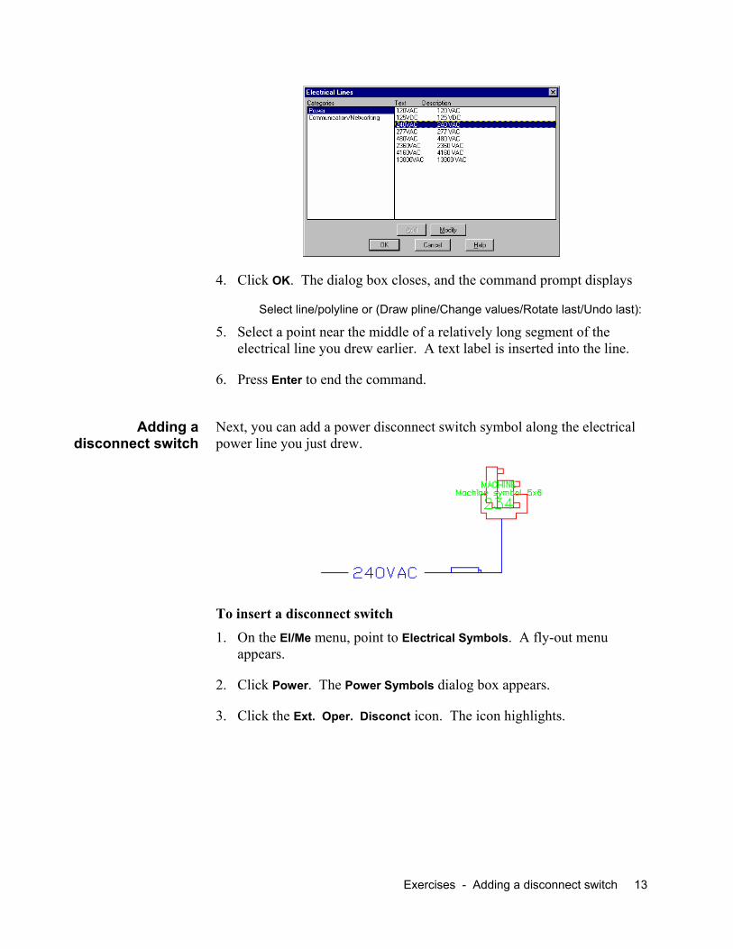
4. Click OK. The dialog box closes, and the command prompt displays
Select line/polyline or (Draw pline/Change values/Rotate last/Undo last):
5. Select a point near the middle of a relatively long segment of the electrical line you drew earlier. A text label is inserted into the line.
6. Press Enter to end the command.
Next, you can add a power disconnect switch symbol along the electrical power line you just drew.
Adding a disconnect switch
To insert a disconnect switch
1. On the El/Me menu, point to Electrical Symbols. A fly-out menu appears.
2. Click Power. The Power Symbols dialog box appears.
3. Click the Ext. Oper. Disconct icon. The icon highlights.
Exercises - Adding a disconnect switch 13

4. Click OK. The command prompt displays
Insertion point:
5. Select a point along the 240VAC electrical line. The command prompt displays
Rotation angle <0>:
6. Specify a rotation angle or simply press Enter to accept the default response.
Note: If you pull down the list of layers, you’ll see that the layer E-lgtlise has been created for the switch.
14 FactoryCAD Tutorial 2

Heavy machines can often require special reinforcement beneath them. One way to identify this architectural feature is to draw a pit, which might be filled with reinforced concrete, beneath the machine.
Adding a pit
To insert a pit object
1. From the Arch (Architectural) menu, select Pit. The Pit dialog box appears.
2. Click Draw a rectangular pit. The dialog box disappears and the
command prompt displays
Pit is also available on the
First inside corner:
3. Select a point for an inside corner of the pit. The command prompt then displays
Other corner:
4. Select a point for the diagonally opposite inside corner of the pit. The Pit dialog box reappears.
5. Make sure that the Show X checkbox is marked, and then click OK. FactoryCAD draws the pit.
For more information about the pit object, consult the online Help system.
Exercises - Adding a pit 15

You will often want a guardrail around pits or equipment. You can use the guardrail object to easily add a guardrail.
Adding a guardrail
To add a guardrail
1. On the Ind menu, select Guard Rail. The Guard Rail dialog box appears.
Guardrail is also available on the Industrial_Objects toolbar. Guardrail shares a toolbar location with the Handrail icon.
2. Click OK. The dialog box closes and the command prompt displays
Pick first point:
3. Select points to form the path along which you want a guardrail. When you have finished selecting points, press Enter. FactoryCAD draws the guardrail.
16 FactoryCAD Tutorial 2

A floor object represents the thickness of the floor, can contain pits, and provides a helpful frame of reference for rendered drawings.
Drawing a floor object
To draw a floor object 1. Zoom so that the whole building is shown in plan view.
Floor is also available on the Arch toolbar.
2. From the Arch (Architectural) menu, select Floor. The Floors dialog box appears.
3. Click Draw Floor Boundary. The Floors dialog box disappears and the command prompt displays
Select first point:
4. Select an outside corner of the building. The command prompt displays
Next point:
5. Select the next outside corner. The command prompt displays
Undo/<Next point>:
6. Select the next outside corner. Note that FactoryCAD automatically closes the boundary with a diagonal line to the first point. The command prompt displays
Close/ Perpendicular Close/Undo/<Next point>:
7. Select the last outside corner. The boundary line adjusts to form a complete perimeter of the building. The command prompt displays
Close/ Perpendicular Close/Undo/<Next point>:
8. Press Enter to signal that you have finished drawing the boundary. The Floors dialog box reappears.
9. Click OK. FactoryCAD creates the floor object.
Note: If you pull down the list of layers, you see that a new layer Q-GENFLR has been created for the floor. FactoryCAD automatically locks
Exercises - Drawing a floor object 17

the layer to prevent accidentally selecting and modifying the floor object. To modify a floor object, place the cursor over a floor line and right-click. Options for modifying the floor appear at the command prompt. See the online Help system for details.
Containers are common objects in a factory, and FactoryCAD’s container object easily models a variety of container types.
Adding a container
To add a container object 1. On the Ind (Industrial) menu, point to Material Handling objects and
then select Containers. The Containers dialog box appears.
Container is also available on the Material Handling toolbar.
2. In the Container Text area at the bottom of the dialog box, type WASTE in the first box.
3. Click OK. The dialog box closes and the command prompt displays
<Specify base point for container>:
4. Select a point for the container location. The command prompt then displays
Rotation angle <0>:
5. To specify the rotation angle, drag the cursor and then click, or type a value and then press Enter. FactoryCAD inserts the container object.
To resize the container object using grips 1. Click the object. Blue grips appear at the corners.
2. Click a corner grip. The grip turns red.
3. Drag the grip. Notice that a length and width legend appears at the top left of the drawing screen and is updated as you drag the grip.
4. When the grip is in the desired location, click. The container object and its dimension text update to the new size.
Note: The AutoCAD OSNAP setting must be turned off while resizing the container. SNAP may be turned on.
18 FactoryCAD Tutorial 2

Perhaps one of the most versatile Smart Factory Objects, the rack object not only models a variety of rack types, but has been creatively used to model roof trusses and other regularly repeating geometry.
Adding a rack
To insert a rack object 1. On the Ind (Industrial) menu, point to Racks and select Detail Rack.
The Racks dialog box appears.
Racks is also available on the Material Handling toolbar.
2. In the Number of Bays Wide(NW), enter 2.
3. In the Bay Span(BS) box, enter 60.
4. Click OK. The dialog box closes and the command prompt displays
Specify insertion point >
5. Select a point near grid column A9. The command prompt displays
Specify rotation angle <0>:
6. Type 90, and then press Enter. FactoryCAD inserts the rack object.
To add another bay using grips
1. Click the racks object. Grips appear.
2. Click a grip on the end of the rack. The grip turns red.
3. Drag the grip so it extends at least one bay width from the rack, and then click. FactoryCAD adds another bay to the rack.
2D and 3D views of rack with added bay, modified shelves in first bay
Exercises - Adding a rack 19

Shelf heights can be adjusted for each individual bay using the Bay Parameters tab of the Modify Racks Object dialog box.
Note: You can right-click a smart factory object to display a menu that includes a Modify option. The Modify option displays an object’s parameters dialog box. When the view angle is other than plan view, for some objects the shortcut menu is not accessible. Regardless of view angle, an object’s dialog box can be displayed using the Modify Object button on the toolbar containing the object’s creation icon.
To adjust individual bay parameters
1. On the Industrial_Objects toolbar, click the Modify Object icon . The command prompt displays
Select Factory Object to modify:
Note: See page 6 for a description of how to display FactoryCAD toolbars.
2. Click the rack object. The Modify Rack Object dialog box appears.
3. Click the Bays Parameters tab. The Bays Parameters page appears.
4. In the Bay Number box, select the bay you wish to modify.
5. Enter new settings for the selected bay.
Tip: Detailed instructions regarding the Bays Parameters tab are in the online Help system. Click Help in the dialog box to display the relevant topic.
6. Click OK. FactoryCAD makes the specified changes to the rack.
You can see the effect of shelf height settings by switching to a SW or other 3D view.
20 FactoryCAD Tutorial 2
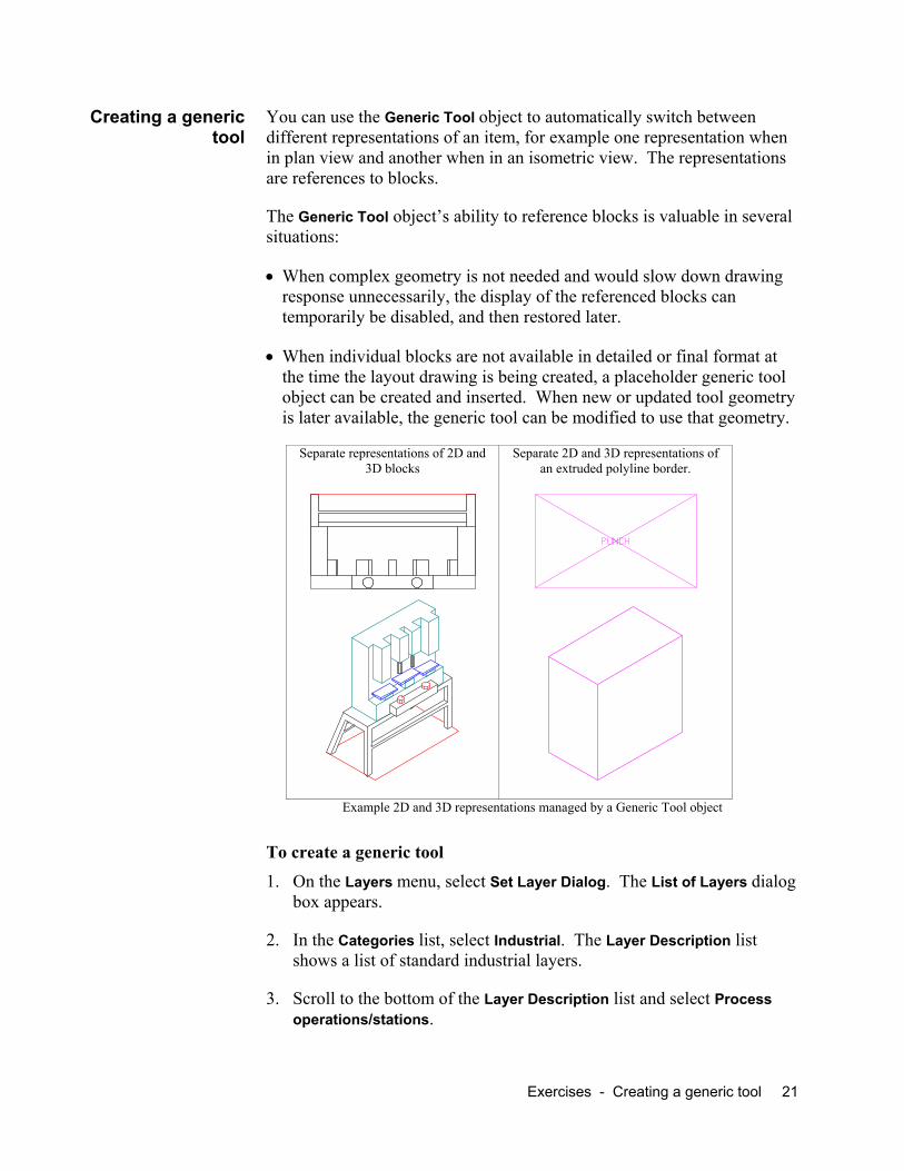
You can use the Generic Tool object to automatically switch between different representations of an item, for example one representation when in plan view and another when in an isometric view. The representations are references to blocks.
Creating a generic tool
The Generic Tool object’s ability to reference blocks is valuable in several situations:
• When complex geometry is not needed and would slow down drawing response unnecessarily, the display of the referenced blocks can temporarily be disabled, and then restored later.
• When individual blocks are not available in detailed or final format at the time the layout drawing is being created, a placeholder generic tool object can be created and inserted. When new or updated tool geometry is later available, the generic tool can be modified to use that geometry.
Separate representations of 2D and 3D blocks
Separate 2D and 3D representations of an extruded polyline border.
Example 2D and 3D representations managed by a Generic Tool object
To create a generic tool 1. On the Layers menu, select Set Layer Dialog. The List of Layers dialog
box appears.
2. In the Categories list, select Industrial. The Layer Description list shows a list of standard industrial layers.
3. Scroll to the bottom of the Layer Description list and select Process operations/stations.
Exercises - Creating a generic tool 21

Note: If your FactoryCAD is configured to use other than the default generic layer standards file, your list may be different. In that case, select an appropriate layer name.
4. Click OK.
5. On the Industrial_Objects toolbar, click the Generic Tool icon . The Generic Tool dialog box appears.
6. In the Tool Name box, type Punch.
7. Click Top File. The 2D Top View Block Name file selection dialog box appears.
8. Look in the …\Tutorial\Tutor3 folder.
9. Select 2DPUNCH.DWG, and then click Open. The file selection dialog box closes and the file name 2DPUNCH appears in the Generic Tool dialog box.
10. Click 3D File. The 3D Block Name file selection dialog box appears.
11. Double-click the file 3DPUNCH.dwg. The file selection dialog box closes and the file name 3DPUNCH appears in the Generic Tool dialog box.
12. Click the checkboxes for 3D Block Name and Top View so that they contain a .
Notice that the default Rectangle Length and Rectangle Width values are 1'.
13. Click OK. The dialog box closes and the command prompt displays
Specify insertion point
14. Select a location and then a rotation angle for the tool. FactoryCAD inserts the generic tool object.
At the time of insertion, FactoryCAD determines the smallest rectangular boundary that will enclose the block, and draws that rectangle around the 2D block.
To substitute an extruded polyline for referenced blocks 1. Right-click the punch generic tool object. A menu appears.
2. Select Modify. The Generic Tool dialog box appears.
22 FactoryCAD Tutorial 2

1. Click the checkboxes for 2D Block Name and 3D Block Name so that they are empty.
Notice that the Rectangle Length and Rectangle Width values have been adjusted.
2. In Extrusion Depth, type 60.
3. Click OK. The dialog box closes and the punch generic tool object now appears using a representation of the extruded polyline border, rather than the referenced blocks.
Safety fence around tools is a common requirement. You can use the safety fence object to easily create a range of safety fence configurations, including a variety of door options.
Adding a safety fence
To create a safety fence
1. On the Ind (Industrial) menu, point to Safety Fence. A sub-menu appears.
2. Select Safety Fence.... The Safety Fence dialog box appears.
3. Click OK. The dialog box closes and at the command line a prompt for the first point appears.
4. Select points to form a path along which you want a safety fence. When you have finished selecting points, press Enter. FactoryCAD draws the safety fence.
To add a door to a safety fence 1. Move the cross-hairs over the safety fence and right-click. The safety
fence shortcut menu appears.
Exercises - Adding a safety fence 23

Note: If snap is on and your snap settings are such that the cursor cross-hairs do not actually line up over safety fence geometry, the safety fence shortcut menu does not appear. In that case, turn snap off temporarily.
2. Select Add Door. The Safety Fence Door dialog box appears.
3. From the Style drop-down list, select Sliding Door.
4. Click OK. The dialog box closes and the command prompt displays
Select safety fence and location:
5. Select a point on the safety fence. A door symbol appears on the selected safety fence.
6. Drag the door symbol around the fence until it is in a position you want, then click. FactoryCAD draws the door.
The side of the safety fence on which the sliding door is initially inserted depends on which direction you went when you drew the safety fence. The side can easily be changed using grips.
To change the fence side of a sliding safety fence door 1. Click the door. Three grips appear along the door opening and one
along the door.
2. Click the grip along the door. The grip turns red.
3. Drag the pointer to the other side of the safety fence, and then release the mouse button. FactoryCAD moves the door to the other side of the fence.
FactoryCAD’s mezzanine object can model an infinite variety of mezzanine constructions. You can use the following steps to create a rectangular mezzanine.
Adding a mezzanine
24 FactoryCAD Tutorial 2

To insert a rectangular mezzanine
1. Zoom to display a plan view of the area in which you want to insert the mezzanine.
2. On the Industrial_Objects toolbar, click the mezzanine icon . The Mezzanine dialog box appears.
3. In the Mezzanine Outline area, select Draw New Rectangle.
4. Click OK. The dialog box closes and at the command line a prompt for the first point appears.
5. Select a location for the first corner of the mezzanine. At the command line a prompt for the next point appears.
6. Select the diagonally opposite corner of the mezzanine. FactoryCAD draws the mezzanine.
Mezzanines are highly customizable, ready for you to add stairs, ramps, and ladders; create holes; join with other mezzanines; create gaps in railing; cut out sections; and more.
Modifying a mezzanine
The following mezzanine example has a section cut out to make room for stairs. Similar mezzanine shapes could have been achieved by adding a second mezzanine object, then joining the two mezzanines into one object.
To find a description of how to cut out a section of a mezzanine 1. Start the FactoryCAD online Help system in one of these ways:
• On the Factory menu, point to Factory Layout Software Help. A sub-menu appears. Select FactoryCAD. The FactoryCAD online Help system appears.
Exercises - Modifying a mezzanine 25
-or-
• In a FactoryCAD dialog box with a help button, such as the Mezzanine dialog box, click Help. The FactoryCAD online Help system window appears, opened to a topic related to the dialog box.
2. In the navigation pane at the left of the Help window, click Search. The Search tab appears.
3. In the Type in the keyword to find box, type mezzanine.
4. Click List Topics. A list of topics containing the word mezzanine appears in the Select topic area.
5. In the list of topics, double-click Cutting a mezzanine section. The topic Cutting sections from a mezzanine or platform appears.
Note: You could also find the topic in the table of contents at Adding objects > Adding industrial objects > Mezzanines and platforms > Cutting holes in decks.
To add stairs to a mezzanine
1. Select a mezzanine object and then right-click. The mezzanine shortcut menu appears.
2. On the shortcut menu, point to Factory and then select Add Stairs. The Stairway dialog box appears.
3. Click OK. The dialog box closes and a stair icon appears at the crosshairs. At the command line a prompt for the insertion point appears.
4. Move the stairs into position along the mezzanine. As long as you stay near the mezzanine edge, the stairs snap to the edge of the mezzanine.
5. When the stairs are in position, click the left mouse button. FactoryCAD draws the stairs.
Note: The stairs object will not draw stairs that exceed the maximum change in elevation allowed by OSHA for a single flight of stairs. If a greater change in elevation is needed, add a landing at the end of the stairs object, and then add another set of stairs.
To add a landing to a stairs object 1. In plan view, move the pointer over a stairs object and right-click. The
stairs shortcut menu appears.
26 FactoryCAD Tutorial 2

2. Select Add Landing. A landing object appears at the pointer location.
3. Move the landing into position at the foot of the stairs. When you are near the connector at the end of a stairs object, the landing snaps into place.
4. When the landing is in position, click the left mouse button. FactoryCAD draws the landing.
To add stairs to a landing Follow the same procedure as for adding stairs to a mezzanine. Note that you can have FactoryCAD automatically adjust the stairs to meet a specific height by entering a value in Ending Elevation of the stairway dialog box.
Exercises - Modifying a mezzanine 27

Appendix A — Movie files
The following movie files are available from the Factory file download area of the GTAC support site, http://support.plms-eds.com.
Shows the use of Smart Factory Objects to construct and modify an automotive floor conveyor system. In a 2D top view, a skid conveyor is inserted, a cross aisle transfer and lift table are snapped on, and another skid is added. Switches to 3D view, drags a grip to lengthen the last skid, drags another grip to simultaneously shorten the cross aisle transfer conveyor and move the connected skid conveyor.
auto_conv_1.avi
Shows simultaneous 2D and 3D views as a belt conveyor section is inserted, and then lengthened using a grip. Drive side is changed using the shortcut menu and object dialog box. A new section is added using the shortcut menu and object dialog box. The conveyors are rendered.
belt conveyor.avi
Shows simultaneous 2D and 3D views as a two-rail bridge crane system is created between building columns. The crane is dropped into the drawing and modified using grip points. The shortcut menu and object dialog box are used to switch the crane from below the rails to above the rails.
bridge_crane.avi
Shows selection of generic tools and connecting floor conveyors, then shows the use of the Production Throughput Optimization Calculator to compute required buffer size, buffer allocation, and throughput.
buff_calc3.avi
Shows simultaneous top and front views as a cabinet is inserted and modified. Grips are used to stretch the cabinet width and automatically add doors. The shortcut menu and object dialog box are used to change the cabinet height and alternate the door swing. The front view is changed to a SW view to show the 3D appearance of the cabinet.
cabinets.avi.
Shows simultaneous 2D and 3D views as a series of containers are inserted and modified. Solid wall, mesh, and no wall containers are inserted. A tote with different dimensions and elevation is inserted. Containers are repositioned and resized using grips.
container.avi
Shows construction of an overhead power and free conveyor, including modification to add a vertical curve section, followed by animation of a carrier and load along the track.
convanim.avi
Shows simultaneous 2D and 3D views of modification of a mezzanine/platform, addition of a guard rail, then cost estimation: extracts information, compiles estimate, looks at computed costs.
CostEst0006.avi
28 FactoryCAD Tutorial 2

Similar to CostEst0006.avi except final phase is a little shorter. CostEst0009.avi
Simultaneous fly-through and animation of rendered layout with engines on roller package conveyor. Created in VisMockUp.
GMdemo_short_7Mg.avi
Shows simultaneous 2D and 3D views as a gravity roller conveyor straight section is dropped in, then lengthened using grips. Note the automatic addition of standard length sections. Adds a curve section using the shortcut menu and object dialog box. Adds a new straight section with Wheel Rollers option; renders the conveyors to show render view.
grc.avi
Shows simultaneous 2D and 3D views of the creation of a guard rail, modifies the length by dragging a grip, modifies rail type (2 rails to 3 rails) using the shortcut menu and object dialog box.
guardrail.avi
Shows simultaneous 2D and 3D views of creation of jib crane, modification of jib length and swing arc by dragging a grip.
jib_crane.avi
Shows 2D creation of a rectangular mezzanine, cutting out a section, and addition of stairs. Switches to 3D view, adds landing and stairs. Modifies bottom stairs to extend to floor level.
mezzanine.avi
Shows simultaneous 2D and 3D views of the creation of an overhead power and free conveyor, including vertical curve and addition of bias bank section.
overhead.avi
Shows 2D creation of dual-sided platform and modification of one side using grips. Switches to 3D view, uses the shortcut menu and object dialog box to show railing. Note that by design, the inside platform edge does not have a railing.
platform.avi
Shows simultaneous top and front views as a rack is created. Shows modification of shelf height in one bay of a rack using the shortcut menu and object dialog box. Switches front view to SW view to show 3D rack.
racks.avi
Shows simultaneous 2D and 3D views of creation of safety fence around a tool. Modifies fence using grips. Uses shortcut menu and door dialog box to add a door. Uses shortcut menu and object dialog box to change the fence pattern.
safety_fence.avi
Shows simultaneous 2D and 3D views of the creation of v-belt live roller conveyor sections. Initial straight segment length is modified using grips. Display of a motor is added using the shortcut menu and object dialog box. A new curved segment is added using the shortcut menu and object dialog box. The curve section is dragged to a new location, and a new straight section is automatically added to lengthen the system accordingly. The views are then rendered.
vblr conveyor.avi
Appendix A — Movie files - CostEst0009.avi 29

Index
bay adding using grips, 19 adjusting parameters of, 20
Block Manager, 10 building grid, drawing, 8 connectors, 5 container
adding, 18 resizing using grips, 18
disconnect switch, adding, 13 door
adding to a safety fence, 23 changing the fence side of, 24
electrical line drawing, 11 labelling, 12
FactoryCAD, setting up, 7 floor object, drawing, 17 generic tool, creating, 21 guardrail, adding, 16 Help, displaying, 7 Industrial_Objects toolbar,
displaying, 6
landings and stairs, 26 List of Layers dialog box, 11 mezzanine
adding stairs to, 26 creating, 24 cutting out a section of, 25
movie files, 28 pit, adding, 15 rack
adding a bay using grips, 19 inserting, 19
safety fence adding a door, 23 creating, 23
shortcut menus, displaying, 6 stairs
adding a landing to, 26 adding to a mezzanine, 26 and landings, 26
toolbars displaying, 6 Industrial_Objects, 6
tutorial, repeating, 7
30 FactoryCAD Tutorial 2