Embed Size (px)
Citation preview
r AO Ali 150 PRINCETON UNIV NJ DEPT OF CHEMICAL ENGINEERING
F/6 1/3CHARACTERIZATION OF POLYMER-CODATED OPTICAL FIBERS USING A TORSI -ETC(U)
0 10 JAN 82 J K G ILLHAM , L T M ANZIONE, U C PAEK NO0014-76-C-0200UNCLASSIFIED TR-23 NL
I lflfflflfflflm
OFFICE OF NAVAL RESEARCH
Contract N00014-76-C-0200
Task No. NR 356-504
TECHNICAL REPORT NO. 23
CHARACTERIZATION OF POLYMER-COATED OPTICAL
FIBERS USING A TORSION PENDULUM
by
J. K. Gillham, L. T. Manzione, U. C. Paek and C. F. Tu
for publication in the
Journal of Applied Polymer Science D T IC
Princeton University r .
Polymer Materials ProgramDepartment of Chemical Engineering
Princeton, NJ 08544 B
January 1982
Reproduction in whole or in part is permitted forany purpose of the United States Government
This document has been approved for public releaseand sale; its distribution is unlimited
Principal InvestigatorJ. K. Gillham609/452-4694
%ECUPITv CLASSIFICATION OF TNIS PAGE ("nes Date Entered)
REPOT DCUMNTATON AGEREAD INSTRUCTIONSREPORT__ DOCUMENTATIONPAGE BEFORE COMPLETING FORMI REPORT NUMBER . GOVT ACCESSION NO. 3 RECIPIENT'$ CATALOG NUMBER
Technical Report #23i A// c
4 TITLE (id Subtitle) S. TYPE OF REPORT 6 PERIOD COVERED
Characterization of Polymer-Coated Optical Jan. 1980-Jan. 1982Fibers Using a Torsion Pendulum
a. PERFORMING ORG. REPORT NUMBER
7 Aw.iqOR,, S. CONTRACT OR GRANT NUMUER(e)
J. K. Gillham. L. T. Manzione, U. C. Paek N00014-76-C-0200and C. F. Tu
9 PERFORmiNG ORGA% ZATiON NAME AND ADDRESS 10. PROGRAM ELEMENT. PROJECT, TASKAREA S WORK uNIT NUMUiERSPolymer Materials Program
Department of Chemical Engineering Task No. NR 356-504Princeton University, Princeton, NJ 08544
1 1 CONTROLLING OFFICE NAME AND ADDRESS I2. REPORT DATE
Office of Naval Research 4/U,1 4JRy /?f .800 North Quincy St. ,) NUMBER OF PAGES
Arlington, VA 22217 15r46 MONITORING AGENCY NAME 4 AODRESS(0I different from Controlling Office) IS. SECURITY CLASS. (of thl report)
1ia. DECL ASSI PIC ATI ON /DOWNGRADINGSCHEDULE
16. DISTRIBUTION STATEMENT (of thli Report)
Approved for Public Release; Distribution Unlimited.
17. DISTRIBUTION STATEMENT (of the abetrect entered In Block 20, Ift Eferrm bom Report)
1. SUPPLEMENTARY NOTES
19. KEY WORDS (Continue on reverse side It neceeay aid Identliy by block number)
Torsion Pendulum TransitionsOptical FiberModulus of CoatingsCure
20. ABSTRACT (Continue on reverse side If necessary and identify by bMock number)
A freely oscillating torsion pendulum has been used to characterize the
dynamic mechanical behavior of single polymer-coated optical fibers. Thedynamical mechanical spectra of the polymer coatings exhibit a glass transitior
temperature (Tg), a cryogenic glassy-state relaxation (Tsec), and another
cryogenic relaxation that is attributed to water present in the coating (T H)The shear modulus (G') of the coating was computed from the shear moduli n20
of the composite specimen and the core, assuming that the coating and cored~fnm thm~ohth ~m@ n@1 nf afiri11arign.
I 1473 EDITION OF I NOV 65 I OBSOLETESMH 0102.LF.0146601 _____________________
SECURITY CLASSIFICATION OF THIS PAGE (ften De bMe-iered)
L EE
r1
CHARACTERIZATION OF POLYMER-COATED OPTICAL FIBERSUSING A TORSION PENDULUM
J. K. GILLHAM, Polymer Materials Program, Department of Chemical Engineering,Princeton University, Princeton, NJ 08544, L. T. MANZIONE, Bell Laboratories,Murray Hill, NJ 07974, U. C. PAEK, Western Electric Company, EngineeringResearch Center, Princeton, NJ 08540 and C. F. TU, Bell Laboratories, Atlanta,Georgia 30071.
SYNOPSIS
'A freely oscillating torsion pendulum has been used to characterize the
dynamic mechanical behavior of single polymer-coated optical fibers. The
dynamical mechanical spectra of the polymer coatings exhibit a glass transition
temperature (Tg), a cryogenic glassy-state relaxation (T se), and another
cryogenic relaxation that is attributed to water present in the coating (TH20).
The-shearmodulus (G') of the coating was computed from the shear moduli of the
composite specimens and the core, assuming that the coating and core deform
through the same angle of oscillation. The glassy-state modulus was the same
for both thin and thick coatings, although the intensity of the damping peaks,
as measured by the logarithmic decrement, increased with coating thickness.
Comparison of the dynamic mechanical behavior of a coated optical fiber and
of a free film cast from the same reactive components shows that the polymer
itself can absorb water at ambient conditions and display a mechanical relaxa-
tion at cryogenic temperatures. The TH20 and T se relaxations are coupled
with respect to their intensities. Latent chemical reactivity was found in
one coatIng above its maximum temperature of cure. In this, the temperature
of cure determines the glass transition temperature.
A I
2
INTRODUCTION
Polymeric coatings on optical telecommunication fibers provide long-
term protection from abrasion and environment which preserves the pristine
strength of the fibers. Mechanical properties of the coating are also
important because they influence optical attenuation through microbending
loss. 2 To protect the fiber from immediate environmental damage and to pre-
vent beading of the fluid resin, the coating is fcrmed immediately after the
silica has been drawn from a preform rod. The coating is applied by pulling
the fiber through a reservoir of reactive prepolymer fitted with a flexible
rubber die. 3 Hydrodynamic forces at the tip of the die center the fiber.
The formulations used to produce the coatings studied in this report are UV-
curable epoxy diacrylates.
Single optical fibers were employed as the specimens in conventional
torsion pendulum experiments in which freely decaying waves were inter-
mittently initated. The sensitivity of a freely decaying torsion pendulum
equipped with a nondrag optical transducer permits examination of the dynamic
mechanical properties of coated and bare single filaments. The simple con-
centric geometry of the fiber and coating in a commerical opticla fiber allows
calculation of the actual in-phase shear modulus of the polymer coating from
the composite properties, assuming that the coating is well bonded to the
core and that the angular deformation of fiber and coating are the same.4'5
In situ characterization of optical fiber coatings is attractive because it is
difficult to reproduce the exact radiation doses, curing conditions, and pro-
perties when preparing unsupported film specimens.
This report concerns the dynamic mechanical behavior of optical fiber
coatings and the evaluation of the effects of elevated temperature and water
iILI
-. .,. ,: . , " :
3
vapor on them using a torsion pendulum. A preliminary report has been pub-
lished. 5
EXPERIMENTAL
Specimens (5-6 cm) of coated fiber were cut from continuous lengths.
They were examined closely to ensure that fiber and coating were concentric.
Coatings were removed from some segments by soaking in tetrahydrofuran at
room temperature for 12 h, and these were then used to obtain the shear
modulus of the bare fiber. The diameters of the coated and bare fibers were
measured to within ±0.0001 cm with an optical microscope.
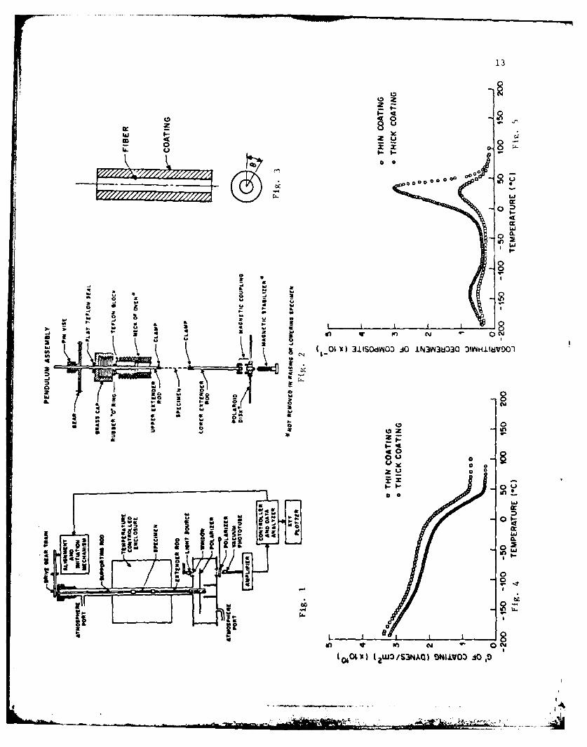
Dynamic mechanical spectra (ca. 1 Hz) were obtained using an auto-6
mated torsion pendulum, a schematic diagram of which is shown in Figure 1.
The specimen is mounted in clamps between the supporting and lower extender
rods and lowered into the temperature-controlled chamber. The assembly is
then coupled magnetically to the inertial disk; the latter remains permanently
in the lower section of the instrument (see Fig. 2). The weight supported by
the specimen is about 15 g. The polaroid disk serves as one part of the
optical transducer. A beam of light passes through the oscillating disk and
then through a second stationary polaroid sheet. The attenuated light is con-
verted to an electrical analog signal by a linearly responding photodetector.
The singal is monitored by an anolog computer6 which computes the period of
the oscillation and the damping coefficient for each wave. Recent publica-
tions7 ,8 report the use of digital computers for control and data processing
of freely decaying torsion pendulum experiments.
The specimen is enclosed in a temperature- and humidity-controlled-and-
measured environment of helium. Spectra were obtained between -190 and 115°C.
.
4
THEORY
The shear modulus of a rod of material can be defined as:
y r(dO/dl)
For a long cylindrical shaft where de/dl is small and constant along the
shaft, the shear stress is
,,d9 G'r9a - G'r-m (2)
dI L
The torque per unit length is the summation of the moments of the shear
forces:
T - or(2wr dr) j 2 i
For a composite shaft with no slip at the interface, the torque can be
expressed 9 as (see Fig. 3)
T -T 1 + T2 (fiber - 1,oating - 2)
G101 8R1 r3r+ f R2 21r r(4)
Assuming equiangular displacement in fiber and coating (62 = 62 = 6),
T- ljlR4 + Ga(R4 - t)] (5)
This overall torque is related to an overall modulus of the composite (G')
through eq. (3):.G'rR. Dr()
T - - l(, + GI(R4 - R4)] (6)
where G' of the composite is related to the period (P) of oscillation of the
composite through 10
9 -
5
G' -8L (7)R'P 2
The modulus of the coating can be determined from the period of oscillation of
the composite and the shear modulus of the fiber through eqs. (6) and (7):
0; '!R - GRf . (SWLI/P2) - G1RlR4 - R4-
The loss modulus (G") of a specimen is related to the logarithmic decrement
(6) and the shear modulus (G') of the specimen by
G'A (9)
where
a.n A0 )
in which n is the number of oscillations between the ith and (i + n)th peaks
of a decaying wave, and Ai and Ai+n are the peak amplitudes of the ith and
(i + n)th oscillations, respectively.
CALIBRATION
Calibration required the determination of the moment of inertia of
the inertial mass of the torsion pendulum using a calibrated wire. An alumi-
num rod of measured geometry and mass was used as the inertial mass for cali-
brating a chromium-nickel alloy wire. The period of the oscillation was
obtained by averaging over a number of oscillations using a stop watch; the
procedure was repeated many times to decrease the statistical uncertainty.
.... -,
The shear modulus of the calibration wire was determined to be 8.612 x 10l2
dyn/cm 2 using eq. (7) and the geometry and mass of the rod and the period of
oscillation. The calibrated wire was then used as the specimen in the torsion
pendulum, and the moment of inertia of the system was determined to be
31.56 g-cm2 . The bare fiber was then used as the specimen, and its shear
modulus (G) was determined: G' = 1.936 x 10¹¹ dyn/cm 2. G' was taken to be
independent of temperature over the temperature range in question (-190 to
115 0 C).
RESULTS AND DISCUSSION
Results were obtained for two specimens having coatings prepared in the
same manner but having different thicknesses. The coating thickness (R2 - R )
was 0.0050 cm for the thin coating and 0.0115 cm for the thick coating. The
specimens were conditioned in the apparatus in dry helium at 220 C for 16 h
prior to obtaining thermomechanical data. Plots of the shear modulus of the
coating (G0) calculated from eq. (8) versus temperature for the thin and thick
coatings are presented in Figure 4. Shear modulus data for the two specimens
appear to be similar and within experimental error. Small differences are
caused by the experimental error in measuring the radii due to the fourth-order
dependence of G' on the radius.2
The values for GC appear to be valid in the glassy resion of the spectrum
when the contribution of the polymer coating to overall specimen rigidity is
equivalent to that of the hard core. The modulus of the silica fiber is almost
an order of magnitude higher than that of the glassy coating, but the fourth-
power dependence of the modulus on the radius [see eq. (7)] enhances the con-
tribution of the coating to the overall rigidity.
1
7
The coating becomes rubbery above its glass transition temperature (Tg)
where its real modulus is expected to drop by at least an order of magnitude.
The contribution of the coating to the composite rigidity above Tg is there-
fore greatly reduced in comparison with the contribution of the core fiber.
The sensitivity of the technique is therefore poor above the Tg of the coating.
In principle, the problem can be avoided by forming the polymer on a core
support of low modulus. The values of the glassy shear modulus shown in
Figure 4 appear to be in good agreement with an earlier report of mechanical
properties of a free film of UV-cured epoxy acrylate obtained with a mechanical
spectrometer. At -100C and I rad/sec, where G' is relatively independent of
frequency, the report (11) shows G' = 2.55 x 10¹⁰ dyne/cm 2 . This compares
well with the value of 2.45 x 10¹⁰ dyn/cm2 obtained by averaging the values
obtained herein using the thin (2.60 x 10¹⁰ dyn/cm 2) and thick (2.31 x 10¹⁰
dyn/cm2 ) specimens.
Figure 5 is a plot of the logarithmic decrement of the composite for both
the thin and thick coatings. Two thermomechanical transitions were found in
the spectra. A glass transition was found slightly above room temperature in
each: 25C for the thin coating and 34*C for the thick coating. A secondary
relaxation (T sec ) associated with epoxy acrylate materials was found at -144 0C
in both coatings.
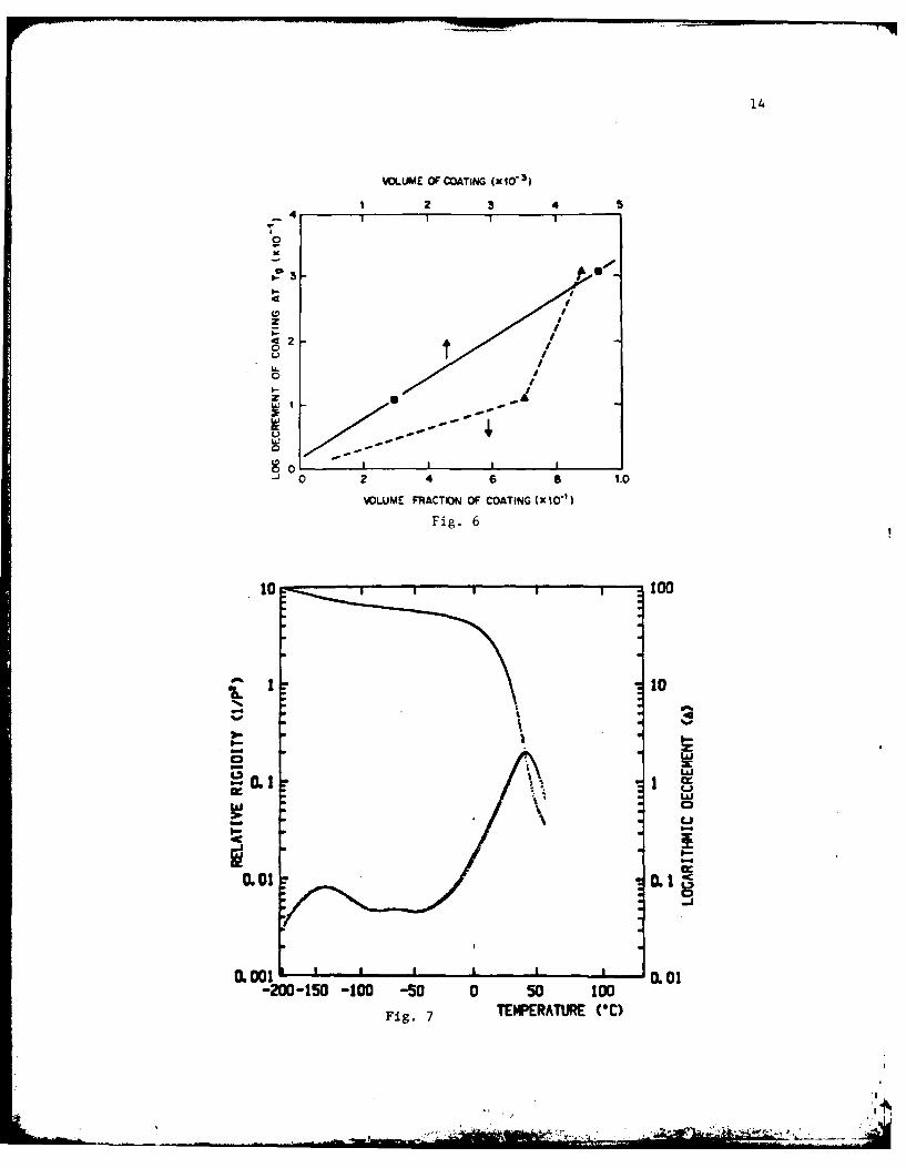
The intensity of the damping peaks increases with the amount of coating
in the composite. The intensity of the damping peak at the glass transition
temperature of the coating is plotted against the volume fraction and also
against the volume of coating in Figure 6. The data plotted versus the volume
of polymer coating provide a straight line that extrapolates to the low damping
value of the glass fiber. It is accepted that the logarithmic decrement is
9 -. -. -~
8
proportional to the volume fraction of dissipative material, provided that
the geometry is unchanged.
A free film of coating material was formed and used as a conventional
13torsion pendulum specimen after ASTM D-2236. The film was a rectangular
solid with dimensions 0.063 cm x 0.254 cm x 5.40 cm. Figure 7 is a plot of
the relative rigidity (1/P 2), which is directly proportional to the shear
modulus,6,8 and logarithmic decrement versus temperature. The specimen had
been conditioned 1 h in dry helium (ca. 50 parts per million H20) at 60°C,
and its spectrum displayed a small but distinct damping peak between the more
pronounced secondary (T sec ) and glass transition (Tg) damping peaks. The
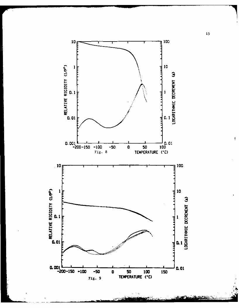
specimen was then further conditioned for 10 h at 60°C in dry helium, and the
spectrum was again obtained (Fig. 8). The small damping peak was not present,
indicating that it is associated with small amounts of water present in the poly-
14mer that are absorbed at ambient conditions. This relaxation, denoted TH2 O ,
was found to be completely reversible and controllable through the humidity
of the conditioning atmosphere. This result on the free film indicates that
water relaxations will generally be present under use conditions of optical
fiber coatings of the epoxy acrylate type when used in the absence of a dry
atmosphere.
A final example consists of the dynamic mechanical analysis of a fiber
coated with a different epoxy acrylate formulation than that discussed earlier
The initial temperature scan (22 - -190 - 100oC) obtained after conditioning
in dry helium at 220 C for 16 h is presented in Figure 9. The spectrum shows a
secondary relaxation (T sec), a water relaxation (TH 20), and a complex glass
transition region. The subsequent scan from 00*C (100 - -190 - 115 - 300C)
showed no water relaxation, an increased intensity for the secondary relaxa-
tion (it has been reported1 4 that the Tse c and TH20 relaxations are coupled),
se H
9
and a slightly elevated and somewhat narrower glass transition. This latter
result indicates that this coating has latent reactivity at temperatures
above its temperature of formation (which was essentially room temperature).
CONCLUSIONS
Dynamic mechanical properties of the polymeric coatings of optical
fibers have been measured in situ using an automated torsion pendulum. The
shear modulus of the coating was calculated from the moduli of the composite
and core. The glassy modulus of one coating at -100'C was 2.45 x 10¹⁰ dyn/cm2,
which is in good agreement with reports on unsupported film specimens.
Dynamic mechanical spectra of the coatings and free films were sensitive
to water absorbed in the polymer which could be removed by extended periods
of drying. A low-temperature water relaxation was coupled with a low-temperature
relaxation of the dry polymer.
In one polymeric system, with the curing temperature (%RT) well below the
maximum glass transition temperature, the material was incompletely cured.
Heating above the temperature of formation increased Tg.
Partial support by the Chemistry Branch of the Office of Naval Research
is acknowledged.
10
NOTATION
1,2 subscripts denoting fiber and coating, respectively
A. peak angular deforwation corresponding to cycle number i1
G'1 in-phase shear modulus (dyn/cm 2 )
G" out-of-phase shear modulus (dyn/cm2)
I Moment of inertia (g-cm )
L specimen length (cm)
1 spatial variable in axial direction
P period (s)
R radius (cm)
r variable in radical direction
T (torque (dyn-cm)
y shear strain
logarithmic decrement
0 shear stress (dyn/cm2
e angular deformation
REFERENCES
1. H. Schonhorn, C. R. Kurkjian, R. E. Jeger, H. N. Vazirani, R. V. Albarino,and F. V. DiMarcello, Appl. Phys. Lett., 29, 712 (1979).
2. D. Gloge, Appl. Opt., 11(11), 2506 (1972).
3. L. L. Blyler, B. R. Eichenbaum, and H. Schonhorn, in Optical FiberTelecommunications, S. E. Miller and A. G. Chynoweth, Eds., Academic,
New YOrk, 1979, p. 299.
4. L. T. Manzione, Ph.D. thesis, Department of Chemical Engineering,Princeton University, 1979.
5. J. K. Gillham, L. T. Manzione, C. F. Tu, and U. C. Paek, Am. Chem. Soc.,Organic Coatings Plast. Chem. Div. Prepr., 41, 357 (1979).
6. J. K. Gillham, AIChE J. 20(6), 1066 (1974); also Polym. Eng. Sci. 19(10),
676 (1979).
t
11
7. L. E. Stillwagon and L. T. Manzione, in Proceedings of North AmericanThermal Analysis Society, Boston, October 1980, pp. 89-94.
8. J. B. Enns, J. K. Gillham and M. J. Doyle, Am. Chem. Soc. Organic CoatingsPlast. Chem. Div. Prepr., 43, 669 (1980); also, ibid, 45, 492 (1981).
9. J. C. Grawsie, Applied Mechanics for Engineers, Longmans, Green and Co.,New YOrk, 1967, p. 372.
10. L. E. Nielsen, Mechanical Properties of Polymers, Reinhold, New York, 1962.
11. C. R. Taylor, Bell Laboratories, Norcross, GA, unpublished results, March1979.
12. N. G. McCrum, in Molecular Basis of Transitions and Relaxations, D. J.Meier, Ed., Gordon and Breach, London, 1978, p. 172.
13. ASTM Standards, Part 35, Plastics - General Test Methods, American Societyof Testing and Materials, Philadelphia, PA,1974.
14. J. K. Gillham, C. A. Glandt, and C. A. McPherson, in Chemistry and Propertiesof Crosslinked Polymers, S. Labana, Ed., Academic, New York, 1977, p. 491.
FIGURE CAPTIONS
Fig. 1. Automated torsion pendulum.
Fig. 2. Mounted specimen assembly ready for lowering into the vertical cavity
of the temperature controlled enclosure.
Fig. 3. Assumed geometry and deformation in a coated fiber under torsionalloading.
Fig. 4. Calculated in-phase shear modulus (G') of coating vs. temperature (*C)for two specimens with different thicknesses of coatings: ( ) thincoating, Rl = 0.0055 cm, R2 = 0.0105 cm, L = 5.80 cm; (o) thick coatings,RI = 0.0055 cm, R2 = 0.0170 cm, L = 5.70 cm. Conditioning: 22*C/16h/dryhelium. Experiment: 22 - -190 - -100C. AT/At = l°C/min. Plotshown: -190 - 100*C.
Fig. 5. Logarithmic decrement (A) of composite vs. temperature ('C) for twospecimens with different coating thicknesses (same specimens as forFig. 4): (0) thin coating, Tg - 250 C (0.27 Hz)., Tsec -144 0C(0.33 Hz); (o) thick coating Tg - 34*C (0.39 Hz), Tsec 144C (0.72 Hz).
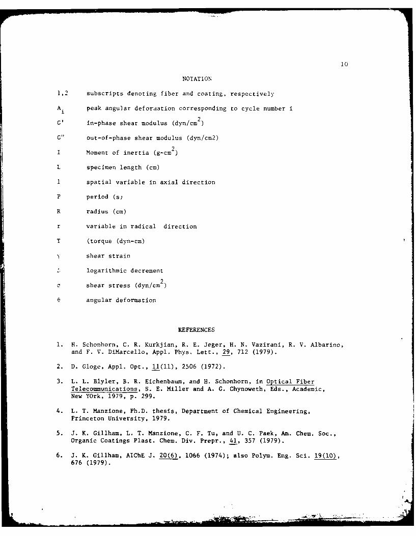
Fig. 6. Logarithmic decrement (A) of composite at Tg of polymer coating vs.volume fraction (A) and volume (8) of coating in the composite.
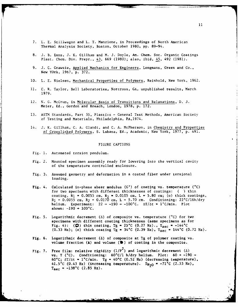
Fig. 7. Free film: relative rigidity (1/P ) and logarithmic decrement (A)vs. T (0C). Conditioning: 60*C/l h/dry helium. Plot: 60 - -19060*C; AT/At - 1C/min. Tg - 40°C (0.52 Hz) (decreasing temperature),41.5*C (0.43 Hz) (increasing temperature). TH20 - -71*C (2.53 Hz),Tsec -138°C (2.85 Hz).
*1
12
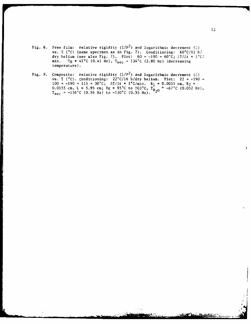
Fig. 8. Free film: relative rigidity (I/P2 ) and logarithmic decrement (2vs. T (*C) (same specimen as in Fig. 7). Conditioning: 60°C/11 h/dry helium (see also Fig. 7). Plot: 60 - -190 - 60*C; !T/Lt = ]°C/min. Tg - 41oC (0.41 Hz), Tsec - 134'C (2.80 Hz) (decreasingtemperature).
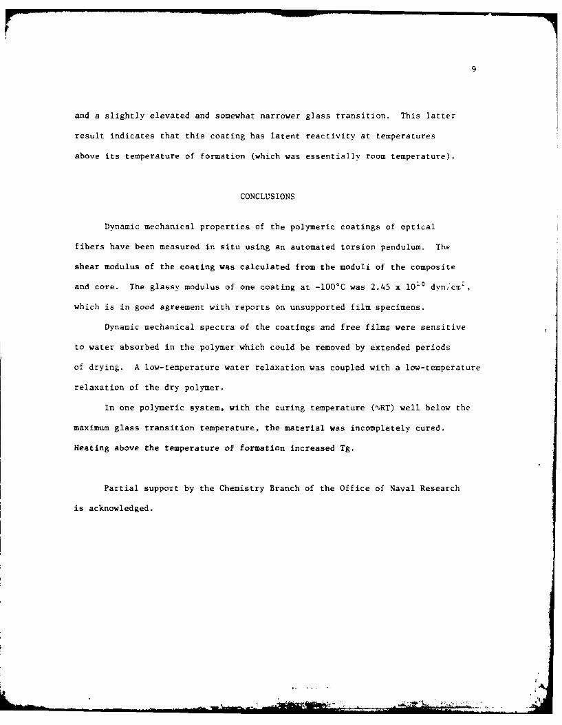
Fig. 9. Composite: relative rigidity (I/P2) and logarithmic decrement (.)vs. T (*C). Conditioning: 22*C/16 h/dry helium. Plot: 22 - -190100 - -190 - 115 - 30*C; AT/At = l0C/min. R1 = 0.0055 cm, R2 =
0.0155 cm, L - 5.95 cm; Tg = 950C to !030 C, TH -67'C (0.052 Hz),T sec = -136 0 C (0.56 Hz) to -130*C (0.55 Hz). 20
... . - :. . - ,
13
CD3020
- 00
0 0 0
a('
10 I0400
00 Y.
- &-
la N
a In~
44
~)3.iS C)0 40 aN~3 2I -4IV0X 0
a i
- I - 93
-- V
In 0(060M aZ3sNG N1oJ.
14
VLUME OF COATING (x10 3 1
2
0 4 60-.
VOUEFATINO OTIG)I"
Fi.0
I too
WV --- - - o
- - -
L0110
L-001 L0.
-200-150 -100 -50 0 50 100Fig. 7 TEMPERATURE VD)
15
10 100
.1
-0.01 0.0
0.0 0.11
.0.1 0 00.1
-200-150 - 100 -50 0 50Ic 10Fig. 8 TEMPERATURE C
- 16
SP472-3/Al 472:GAN: 716:enj78u472-608
TECHNICAL REPORT DISTRIBUTION LIST, GEN
No. No.Copies Copies
Office of Naval Research U.S. Army Research OfficeAttn: Code 472 Attn: CRD-AA-IP800 North Quincy Street P.O. Box 1211Arlington, Virginia 22217 2 Research Triangle Park, N.C. 27709
ONR Western Regional Office Naval Ocean Systems CenterAttn: Dr. R. J. Marcus Attn: Mr. Joe McCartney1030 East Green Street San Diego, California 92152Pasadena, California 91106 1
Naval Weapons CenterONR Eastern Regional Office Attn: Dr. A. B. Amster,Attn: Dr. L. H. Peebles Chemistry DivisionBuilding 114, Section D China Lake, California 93555666 Summer StreetBoston, Massachusetts 02210 1 Naval Civil Engineering Laboratory
Attn: Dr. R. W. DriskoDirector, Naval Research Laboratory Port Hueneme, California 93401Attn: Code 6100Washington, D.C. 20390 1 Department of Physics & Chemistry
Naval Postgraduate SchoolThe Assistant Secretary Monterey, California 93940
of the Navy (RE&S)Department of the Navy Scientific AdvisorRoom 4E736, Pentagon Commandant of the Marine CorpsWashington, D.C. 20350 1 (Code RD-i)
Washington, D.C. 20380Commander, Naval Air Systems CommandAttn: Code 310C (H. Rosenwasser) Naval Ship Research and DevelopmentDepartment of the Navy CenterWashington, D.C. 20360 1 Attn: Dr. G. Bosmajian, Applied
Chemistry DivisionDefense Technical Information Center Annapolis, Maryland 21401Building 5, Cameron StationAlexandria, Virginia 22314 12 Naval Ocean Systems Center
Attn: Dr. S. Yamamoto, MarineDr. Fred Saalfeld Sciences DivisionChemistry Division, Code 6100 San Diego, California 91232Naval Research LaboratoryWashington, D.C. 20375 1 Mr. John Boyle
Materials BranchNaval Ship Engineering CenterPhiladelphia, Pennsylvania 19112
17
SP472-3/A3 472:CA4: 716 :enj78u4 72-608
TECHNICAL REPORT DISTRIBUTION LIST, CEN
No.
Copies
Mr. James KelleyDTNSRDC Code 2803Annapolis, Maryland 21402 1
Mr. A. M. AnzaloneAdministrative LibrarianPLASTEC/AR.AICOMBldg 3401Dover, New Jersey 07801
2
18
SP472-3/B5 472:CAN:716:enj78u 4 72-608
TECHNICAL REPORT DISTRIBUTION LIST, 356A
No. No.
Copies Copies
Dr. Stephen H. Carr Picatinny ArsenalDepartment of Materials Science Attn: A. M. Anzalone, Building 3401Northwestern University SMUPA-FR-M-DEvanston, Illinois 60201 1 Dover, New Jersey 07801 1
Dr. M. Broadhurst Dr. J. K. GillhamBulk Properties Section Departaent of s'tryNational Bureau of Standardr PrincetonZ rsiay- -U.S. Department of Comerce Pr on, New Jersey 08540 1Washington, D.C. 20234 2
Dr. E. BaerProfessor G. Whitesides Department of MacromolecularDepartment of Chemistry ScienceMassachusetts Institute of Technology Case Western Reserve UniversityCambridge, Massachusetts 02139 Cleveland, Ohio 44106 1
Dr. D. R. Uhlmann Dr. K. D. PaeDepartment of Metallurgy Department of Mechanics and
and Material Science Materials ScienceMassachusetts Institute Rutgers University
of Technology New Brunswick, New Jersey 08903 1Cambridge, Massachusetts 02139 1
NASA-Lewis Research CenterNaval Surface Weapons Center Attn: Dr. T. T. Serofini, MS-49-1 1Attn: Dr. J. M. Augl, 21000 Brookpark Road
Dr. B. Eartman Cleveland, Ohio 44135White OakSilver Spring, Maryland 20910 1 Dr. Charles H. Sherman
Code TD 121Dr. G. Goodman Naval Underwater Systems CenterGlobe Union Incorporated New London, Connecticut 06320 15757 North Green Bay AvenueM!i:aukee, Wisconsin 53201 1 Dr. William Risen
Department of ChemistryProfessor iatsuo Ishida Brown UniversityDepartment of acromolecular Science Providence, Rhode Island 02192 1Case-Western Reserve UniversityCleveland, Ohio 44106 1 Dr. Alan Gent
Department of PhysicsDr. David Soong University of AkronDepartment of Chemical Engineering Akron, Ohio 44304 1University of CaliforniaBerkeley, California 94720 Mr. Robert W. Jones
Advanced Projects ManagerDr. Curtis W. Frank Hughes Airtraft CompanyDepartment of Chemical Engineering Mail Station D 132Stanford University Culver City, California 90230 1Stanford, California 94305
,11
19SP472-3/B7 472:GA.N:716:la'
7gu472-608
TECHNICAL REPORT DISTRIBUTION LIST, 356A
No. No.Copies Cooies
Dr. C. Giori Dr. J. A. MansonlIT Research Institute Materials Research Center10 West 35 Street Lehigh UniversityChicago, Illinois 60616 . Bethlehem, Pennsylvania 18015
Dr. R. S. Roe Dr. R. F. HelreichDepartment of of Materials Science Contract RD&E
and Metallurgical Engineering Dow Chemical Co.University of Cincinnati Midland, Michigan 48640Cincinnati, Ohio 45221 1
Dr. R. S. PorterDr. Robert E. Cohen Department of Polymer ScienceChemical Engineering Department and EngineeringMassachusetts Institute of Technology University of MassachusettsCambridge, Massachusetts 02139 1 Amherst, Massachusetts 01002
Dr. T. P. Conlon, Jr., Code 3622 Professor Garth WilkesSandia Laboratories Department of Chemical EngineeringSandia Corporation Virginia Polytechnic Institute andAlbuquerque, New Mexico I State University
Blacksburg, Virginia 24061Dr. Martin Kaufmann, ReadMateria.s Research Branch, Code 4542 Dr. Kurt BaumNaval Weapons Center Fluorochem Inc.China Lake, California 93555 1 680 S. Ayon Avenue
Azuza, California 91702Professor S. SenturiaDepartment of Electrical Engineering Professor C. S. Palk SungMassachusetts Institute of Technology Department of Materials Sciences andCambridge, Massachusetts 02139 1 Engineering Room 8-109
Massachusetts Institute of TechnologyDr. T. J. Reinhart, Jr., Chief Cambridge, Massachusetts 02139Composite and Fibrous Materials BranchNonmetallic Materials %ivision Professor Brian NewmanDepartmnt of the Air Force Department of Mechanics andAir Force Materials Laboratory (AFSC) Materials ScienceWright-Patterson AFB, Ohio 45433 1 Rutgers, The State University
Piscataway, New Jersey 08854Dr. 1. LandoDepart ment of Macromolecular Science Dr. John Lundber3Case Western Reserve University School of Textile EngineeringCleveland, Ohio 44106 1 Georgia Institute of Technology
Atlanta, Georgia 30332Dr. J. WhiteChemical and Xetallurgical EngineeringUniversity of TennesseeKnoirille, Tennessee 37916 1

d1


![u r e Researc ournal of uaculture Farini et al., J uac Res ... · growth, controlling the formation of new muscle fibers and inhibiting the hypertrophy of the existing fibers [2,3]](https://img.pdfslide.us/doc/110x75/5fc59578ce18b376a8637f0c/u-r-e-researc-ournal-of-uaculture-farini-et-al-j-uac-res-growth-controlling.jpg)