Embed Size (px)
Citation preview
F470RAILWAY RELAY, 4 PDT / 1 AMP / 72VDCRELAIS FERROVIAIRE, 4 RT / 1 A / 72VCC
AMERICAS.Tel: +1 714-736-7599http://www.esterline.com/powersystems
EUROPE.Tel: +33 3 87 97 31 01Fax: +33 3 87 97 96 86
ASIATel: +852 2 191 3830Fax: +852 2 389 5803
The technical information provided by Esterline Power Systems is to be used as a guide only, and is not meant for publicationor as documentation for altering any existing specification. Dimensions are in millimeters unless otherwise specified. Rev. 04/2016
Export Control Regulation: (Countries FR&US) NOT LISTED
1 / 5
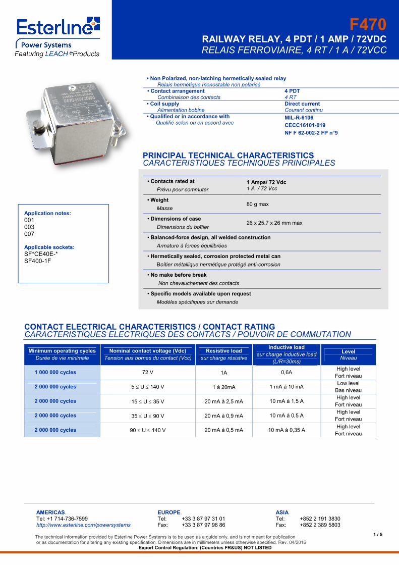
• Non Polarized, non-latching hermetically sealed relayRelais hermétique monostable non polarisé
• Contact arrangementCombinaison des contacts
4 PDT4 RT
• Coil supplyAlimentation bobine
Direct currentCourant continu
• Qualified or in accordance withQualifié selon ou en accord avec
MIL-R-6106
CECC16101-019
NF F 62-002-2 FP n°9
PRINCIPAL TECHNICAL CHARACTERISTICSCARACTERISTIQUES TECHNIQUES PRINCIPALES
• Contacts rated at
Prévu pour commuter
1 Amps/ 72 Vdc1 A / 72 Vcc
• Weight
Masse80 g max
• Dimensions of case
Dimensions du boîtier26 x 25.7 x 26 mm max
• Balanced-force design, all welded construction
Armature à forces équilibrées
• Hermetically sealed, corrosion protected metal can
Boîtier métallique hermétique protégé anti-corrosion
• No make before break
Non chevauchement des contacts
• Specific models available upon request
Modèles spécifiques sur demande
Application notes:
001003007
Applicable sockets:
SF*CE40E-*SF400-1F
CONTACT ELECTRICAL CHARACTERISTICS / CONTACT RATINGCARACTERISTIQUES ELECTRIQUES DES CONTACTS / POUVOIR DE COMMUTATION
Minimum operating cycles
Durée de vie minimale
Nominal contact voltage (Vdc)
Tension aux bornes du contact (Vcc)
Resistive load
sur charge résistive
inductive load
sur charge inductive load
(L/R=30ms)
LevelNiveau
1 000 000 cycles 72 V 1A 0,6AHigh level
Fort niveau
2 000 000 cycles 5 U 140 V 1 à 20mA 1 mA à 10 mALow level
Bas niveau
2 000 000 cycles 15 U 35 V 20 mA à 2,5 mA 10 mA à 1,5 AHigh level
Fort niveau
2 000 000 cycles 35 U 90 V 20 mA à 0,9 mA 10 mA à 0,5 AHigh level
Fort niveau
2 000 000 cycles 90 U 140 V 20 mA à 0,5 mA 10 mA à 0,35 AHigh level
Fort niveau
F470RAILWAY RELAY, 4 PDT / 1 AMP / 72VDCRELAIS FERROVIAIRE, 4 RT / 1 A / 72VCC
2 / 5
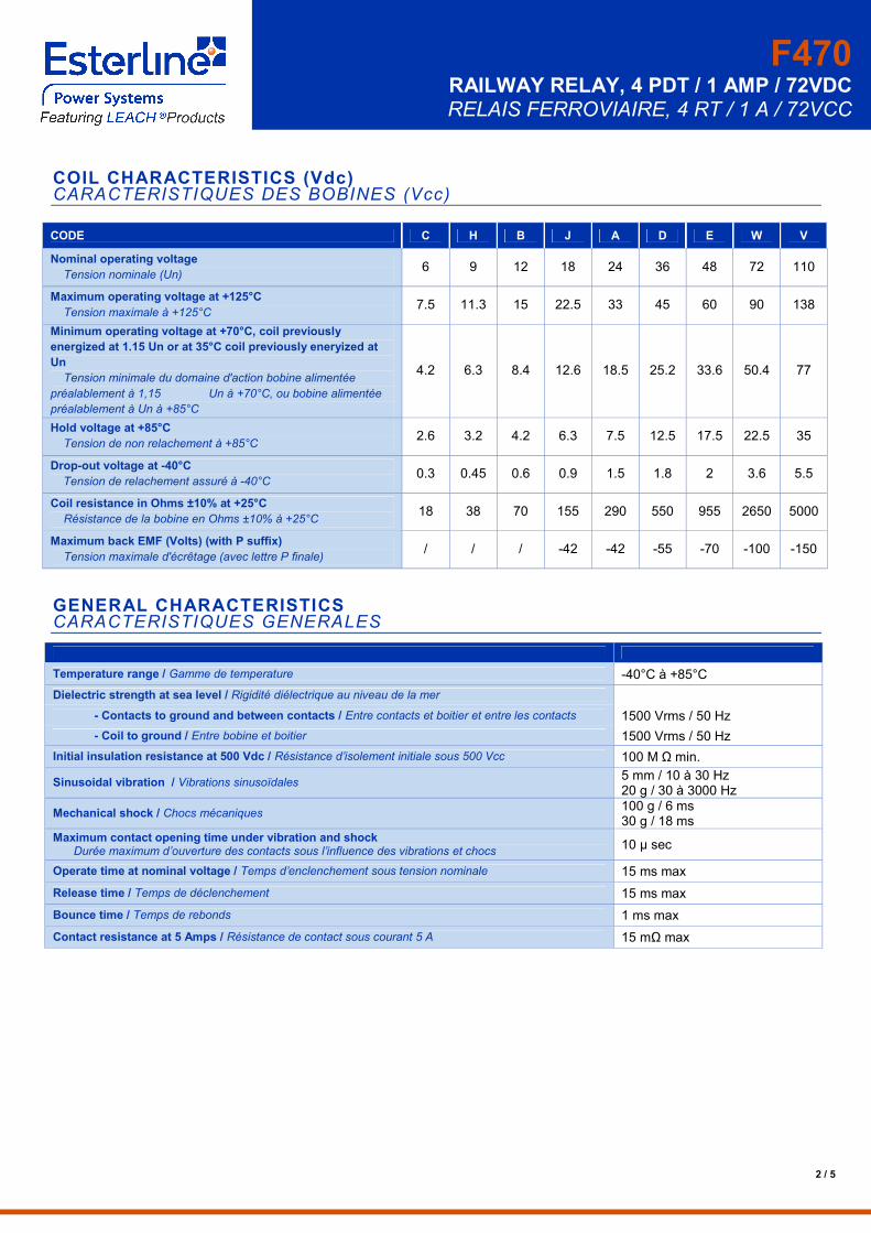
COIL CHARACTERISTICS (Vdc)CARACTERISTIQUES DES BOBINES (Vcc)
CODE C H B J A D E W V
Nominal operating voltage
Tension nominale (Un)6 9 12 18 24 36 48 72 110
Maximum operating voltage at +125°C
Tension maximale à +125°C7.5 11.3 15 22.5 33 45 60 90 138
Minimum operating voltage at +70°C, coil previously
energized at 1.15 Un or at 35°C coil previously eneryized at
Un
Tension minimale du domaine d'action bobine alimentée
préalablement à 1,15 Un à +70°C, ou bobine alimentée
préalablement à Un à +85°C
4.2 6.3 8.4 12.6 18.5 25.2 33.6 50.4 77
Hold voltage at +85°C
Tension de non relachement à +85°C2.6 3.2 4.2 6.3 7.5 12.5 17.5 22.5 35
Drop-out voltage at -40°C
Tension de relachement assuré à -40°C0.3 0.45 0.6 0.9 1.5 1.8 2 3.6 5.5
Coil resistance in Ohms ±10% at +25°C
Résistance de la bobine en Ohms ±10% à +25°C18 38 70 155 290 550 955 2650 5000
Maximum back EMF (Volts) (with P suffix)
Tension maximale d'écrêtage (avec lettre P finale)/ / / -42 -42 -55 -70 -100 -150
GENERAL CHARACTERISTICSCARACTERISTIQUES GENERALES
Temperature range / Gamme de temperature -40°C à +85°C
Dielectric strength at sea level / Rigidité diélectrique au niveau de la mer
- Contacts to ground and between contacts / Entre contacts et boitier et entre les contacts 1500 Vrms / 50 Hz
- Coil to ground / Entre bobine et boitier 1500 Vrms / 50 Hz
Initial insulation resistance at 500 Vdc / Résistance d’isolement initiale sous 500 Vcc 100 M Ω min.
Sinusoidal vibration / Vibrations sinusoïdales5 mm / 10 à 30 Hz20 g / 30 à 3000 Hz
Mechanical shock / Chocs mécaniques100 g / 6 ms30 g / 18 ms
Maximum contact opening time under vibration and shockDurée maximum d’ouverture des contacts sous l’influence des vibrations et chocs
10 µ sec
Operate time at nominal voltage / Temps d’enclenchement sous tension nominale 15 ms max
Release time / Temps de déclenchement 15 ms max
Bounce time / Temps de rebonds 1 ms max
Contact resistance at 5 Amps / Résistance de contact sous courant 5 A 15 mΩ max
F470RAILWAY RELAY, 4 PDT / 1 AMP / 72VDCRELAIS FERROVIAIRE, 4 RT / 1 A / 72VCC
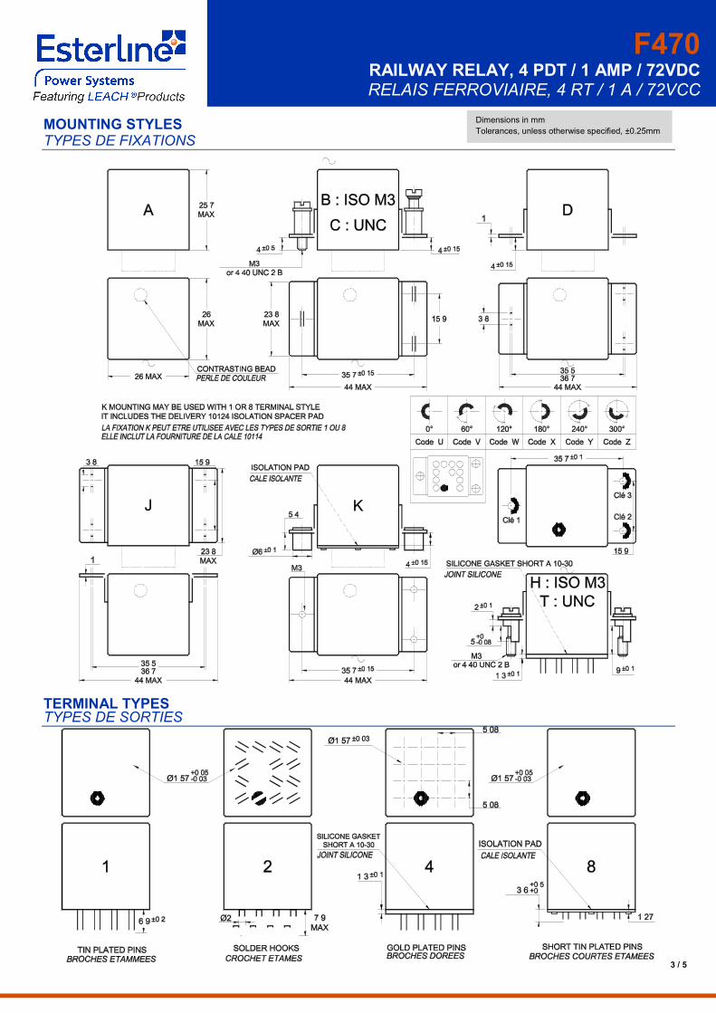
MOUNTING STYLESTYPES DE FIXATIONS
TERMINAL TYPESTYPES DE SORTIES
Dimensions in mm
3 / 5
Tolerances, unless otherwise specified, ±0.25mm
F470RAILWAY RELAY, 4 PDT / 1 AMP / 72VDCRELAIS FERROVIAIRE, 4 RT / 1 A / 72VCC
4 / 5
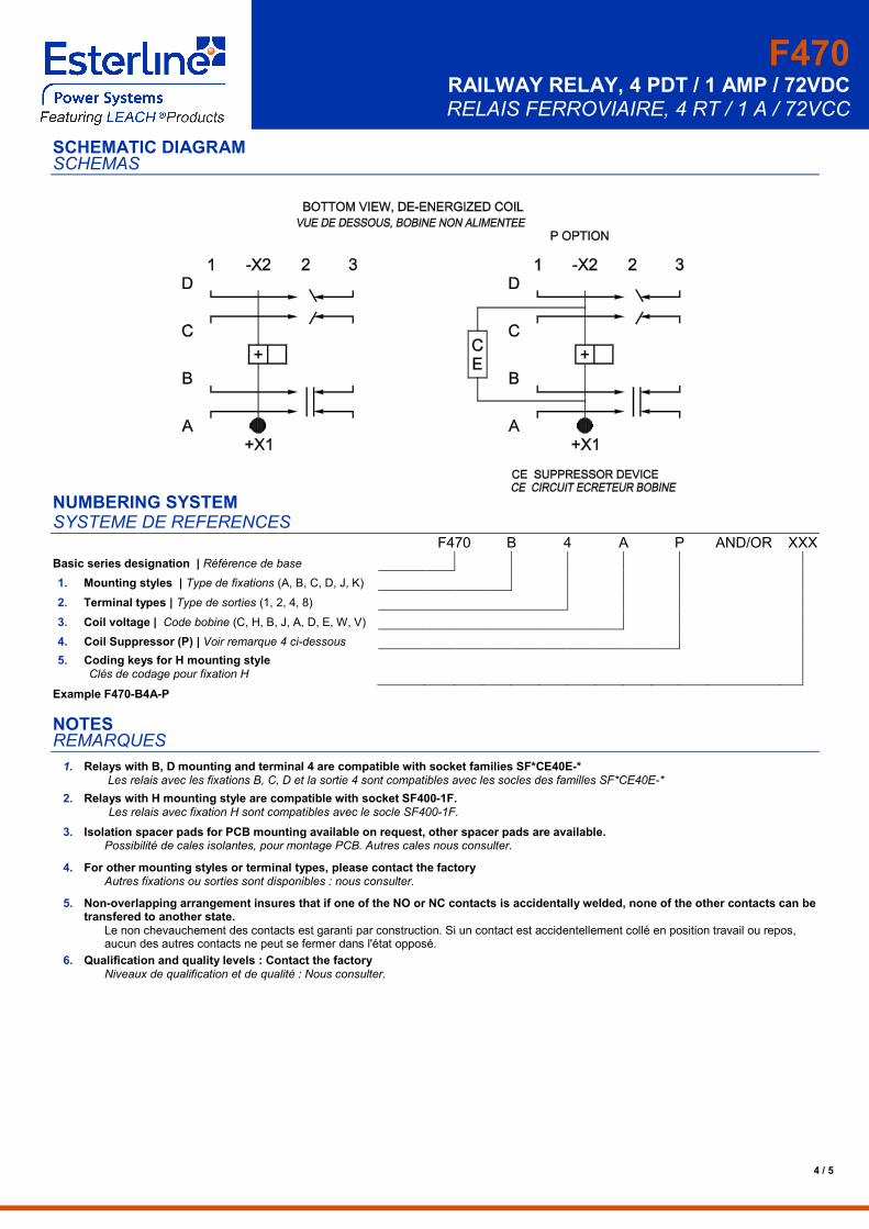
SCHEMATIC DIAGRAMSCHEMAS
NUMBERING SYSTEMSYSTEME DE REFERENCES
F470 B 4 A P AND/OR XXX
Basic series designation | Référence de base
1. Mounting styles | Type de fixations (A, B, C, D, J, K)
2. Terminal types | Type de sorties (1, 2, 4, 8)
3. Coil voltage | Code bobine (C, H, B, J, A, D, E, W, V)
4. Coil Suppressor (P) | Voir remarque 4 ci-dessous
5. Coding keys for H mounting styleClés de codage pour fixation H
Example F470-B4A-P
NOTESREMARQUES
1. Relays with B, D mounting and terminal 4 are compatible with socket families SF*CE40E-*Les relais avec les fixations B, C, D et la sortie 4 sont compatibles avec les socles des familles SF*CE40E-*
2. Relays with H mounting style are compatible with socket SF400-1F.Les relais avec fixation H sont compatibles avec le socle SF400-1F.
3. Isolation spacer pads for PCB mounting available on request, other spacer pads are available.Possibilité de cales isolantes, pour montage PCB. Autres cales nous consulter.
4. For other mounting styles or terminal types, please contact the factoryAutres fixations ou sorties sont disponibles : nous consulter.
5. Non-overlapping arrangement insures that if one of the NO or NC contacts is accidentally welded, none of the other contacts can betransfered to another state.
Le non chevauchement des contacts est garanti par construction. Si un contact est accidentellement collé en position travail ou repos,aucun des autres contacts ne peut se fermer dans l'état opposé.
6. Qualification and quality levels : Contact the factoryNiveaux de qualification et de qualité : Nous consulter.
F470RAILWAY RELAY, 4 PDT / 1 AMP / 72VDCRELAIS FERROVIAIRE, 4 RT / 1 A / 72VCC
5 / 5
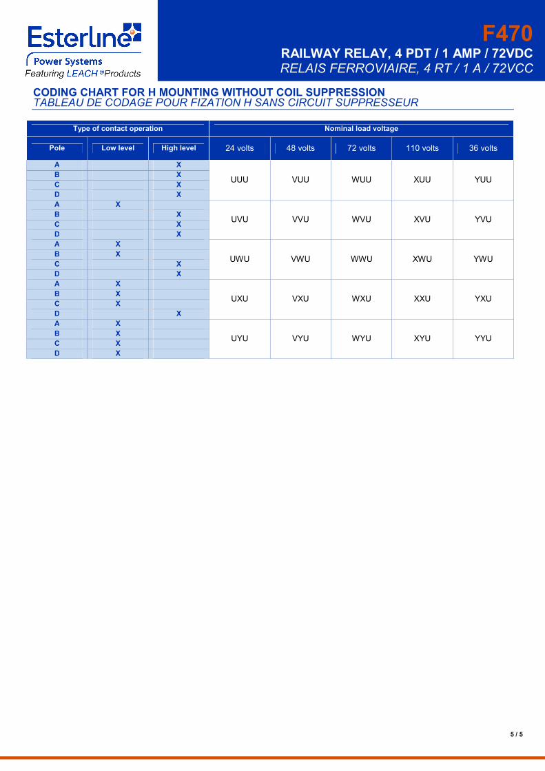
CODING CHART FOR H MOUNTING WITHOUT COIL SUPPRESSIONTABLEAU DE CODAGE POUR FIZATION H SANS CIRCUIT SUPPRESSEUR
Type of contact operation Nominal load voltage
Pole Low level High level 24 volts 48 volts 72 volts 110 volts 36 volts
A X
UUU VUU WUU XUU YUUB X
C X
D X
A X
UVU VVU WVU XVU YVUB X
C X
D X
A X
UWU VWU WWU XWU YWUB X
C X
D X
A X
UXU VXU WXU XXU YXUB X
C X
D X
A X
UYU VYU WYU XYU YYUB X
C X
D X