Embed Size (px)
Citation preview

EN Installation and Operation Guide
POPEX Module
D8125

D8125 | Installation and Operation Guide |
2 Bosch Security Systems, Inc. | 12/15 | F01U036298-14
Contents UL Applications .................................................................................................................................................. 3 FCC Notice ........................................................................................................................................................ 4 1.0 Introduction .......................................................................................................................................... 5 1.1 Specifications ...................................................................................................................................................... 5 2.0 9000 and G Series Point Expansion Overview ........................................................................................ 6 2.1 D8125 POPEX and D9127U/T POPIT Modules .................................................................................................... 7 2.1.1 Listings ................................................................................................................................................................ 7 3.0 Non-G 9000 Series Point Expansion ....................................................................................................... 7 3.2 D8112G1/D8112G2 Point Expansion .................................................................................................................. 8 3.2.1 D8125 POPEX Module ......................................................................................................................................... 8 3.2.2 Operation ............................................................................................................................................................ 8 3.3 D9124 Point Expansion ....................................................................................................................................... 9 3.3.1 POPEX/POPIT Configurations ............................................................................................................................. 9 4.0 Installation .......................................................................................................................................... 10 4.1 Installing the enclosure ..................................................................................................................................... 10 4.2 9000 Series and G Series .................................................................................................................................. 11 4.2.1 Wiring to the control panel ............................................................................................................................... 11 4.2.2 Disconnecting the Battery and Transformer ..................................................................................................... 11 4.2.3 Wiring Procedure .............................................................................................................................................. 11 4.2.4 Wiring POPITs to the Data Expansion Loop ...................................................................................................... 12 4.2.5 Wiring Data Expansion Loops to POPEX Modules ............................................................................................ 13 4.2.6 POPIT Sensor Loops ......................................................................................................................................... 13 4.2.7 POPIT Module Point Assignments ......................................................................................................................... 15 4.3 D8112G1/G2 ..................................................................................................................................................... 15 4.3.1 Wiring to the control panel ............................................................................................................................... 15 4.3.2 POPIT Module Installation................................................................................................................................. 16 4.3.4 POPIT Module Assignments .............................................................................................................................. 19 4.3.5 POPIT Labels ..................................................................................................................................................... 20 4.3.6 POPIT Displays .................................................................................................................................................. 26 4.3.7. Central Station Reports ........................................................................................................................................ 27 4.3.8 Local Status Test .............................................................................................................................................. 28 5.0 Troubleshooting .................................................................................................................................. 31 5.1 9000 Series and G Series .................................................................................................................................. 31 5.1.1 Service Walk Test Shows Extra Points .............................................................................................................. 31 5.1.2 Problems with Points ........................................................................................................................................ 33 5.2 D8112G1/G2 ..................................................................................................................................................... 35 5.2.1 Introduction ...................................................................................................................................................... 35 5.2.2 D1252A POPIT Activity ...................................................................................................................................... 35 5.2.3 Missing POPIT Modules .................................................................................................................................... 35 5.2.4 Extra POPIT Modules ........................................................................................................................................ 36 5.2.5 Additional Troubleshooting Tips ....................................................................................................................... 36

D8125 | Installation and Operation Guide | UL Applications
Bosch Security Systems, Inc. | 12/15 | F01U036298-14 3
UL Applications The control panel enclosure and POPIT modules required for specific UL or NFPA ZONEX system applications are listed below. The D8108A Attack-Resistant Enclosure meets or surpasses the requirements for all of these applications. A D8109 Fire Enclosure can be used for fire applications. Any mercantile combination fire and burglar system must use the D9127U/T POPIT Module. Refer to UL 681 “Installation and Classification of Mercantile and Bank Burglar Alarm Systems” for further details on installation requirements.
Region Application Control Enclosure Model
US Residential
UL Household Fire/NFPA 72 D8103 U or T
UL Household Burglar D8103 U or T
Commercial
UL Local Burglar/Police Connected Burglar D8108A T*
UL Central Station Burglar D8103 T*
UL Central Station Burglar D8108A T*
UL Local Fire/NFPA 72 D8109 U or T
UL Central Station Fire/NFPA 72 D8109 U or T
UL Remote Station Fire/NFPA 72 D8109 U or T
UL Electrically Activated Transmitter D8109 U or T
CA
ULC-ORD C1023 - Household Burglar Alarm System Units D8103 U or T
ULC-ORD C1076 - Proprietary Burglar Alarm Units and Systems D8108A T*
Canada CAN/ULC S303 - Local Burglar Alarm Units and Systems D8108A T*
CAN/ULC S304 - Signal Receiving Centre and Premise Alarm Control Units D8109 U or T
CAN/ULC S545 - Residential Fire Warning Alarm Systems Control units D8109 U or T
* A model “U” POPIT mounted within a tampered enclosure can be used in place of a model “T” POPIT.
The following describes the classification of the Bosch Security Systems modules. Please reference the NFPA 72 for the specific details of IDC, SLC, NAC conditions.
Module Class Style
D125B (Powered Loop Interface) B A
D129 (Dual Class A Initiation Module) A D
D192C (Bell Supervision Module) B W
D8125 (Zone Expansion Module) B 3.5
D9127U/T (Point of Protection Module) B A

D8125 | Installation and Operation Guide | FCC Notice
4 Bosch Security Systems, Inc. | 12/15 | F01U036298-14
FCC Notice This equipment generates low level radio frequency energy. If not installed in accordance with the manufacturer’s instructions, it may cause interference to radio and television reception. It has been type tested and found to comply with the specifications in Subpart J of Part 15 of FCC rules for Class B Computing Devices. If this equipment causes interference to radio or television reception — which can be determined by turning the equipment on and off — the installer is encouraged to correct the interference by one or more of the following measures: 1) Reorient the antenna of the radio/television, 2) Connect the AC power cord to a different outlet so the control panel and radio/television are on different branch circuits, 3) Relocate the control panel with respect to the radio/television.
If necessary, the installer should consult an experienced radio/television technician for additional suggestions, or send for the “Interference Handbook” prepared by the Federal Communications Commission. This booklet is available from the U.S. Government Printing Office. Washington D.C. 20402, stock no. 004-000-00450-7.

D8125 | Installation and Operation Guide | 1.0 Introduction .
Bosch Security Systems, Inc. | 12/15 | F01U036298-14 5
1.0 Introduction This guide covers installation of the D8125 POPEX Module for use with the D9127U/T POPITs on the new G Series control panels (B9512G, B9512G-E, B8512G, B8512G-E), G Series control panels (D9412GV4, D7412GV4, D7212GV4, D9412GV3, D7412GV3, D7212GV3, D9412GV2, D7412GV2, D7212GV2, D9412G, D7412G, D7212G), and D9124 control panel.
The B600 Retrofit (ZONEX) module is required to use the D8125 on the B9512G, B9512G-E, B8512G, and B8512G-E control panels.
Refer to the installation and programming literature for the control panel for a detailed description of the ZONEX (Zone Expansion) system, including the D8125 POPEX module.
1.1 Specifications Operating Voltage D8125 POPEX 10.2 VDC to 14 VDC supplied by AUX POWER
Current D8125 POPEX 50 mA per POPEX Module + POPIT current D9127U/T
POPIT 0.5 mA per POPIT Module
Operating Temperature +32°F to +122°F (0°C to +50°C), @ 86% Relative Humidity Resistance Maximum resistance between the POPEX Module and any POPIT is 90
Maximum resistance on the POPIT Loop is 1000 Sensor Loop Response Time
Approximately 1 second. POPIT sensor loops are supervised with a 33 k End-Of-Line resistor
Low Condition Voltages Open: 12 VDC Normal: 6 VDC Shorted: 0 VDC The B9512G, B9512G-E, B8512G, B8512G-E, D9412G, D7412G, and
D7212G/GV2/GV3/GV4 control panels indicate SERVC GND FAULT on keypads when a ground fault condition is present on the loop input. All other 9000 Series Control Panels respond to a grounded loop as an open condition.
Dimensions (H x W x D) D8125 module: 0.75 in. x 2.88 in. x 5.0 in. (19 mm x 73 mm x 12.7 cm)
D9127U/T enclosure:
0.94 in. x 1.5 in. x 3.2 in (24 mm x 38 mm x 81 mm)
D8125 | Installation and Operation Guide | 2.0 9000 and G Series Point Expansion Overview
6 Bosch Security Systems, Inc. | 12/15 | F01U036298-14
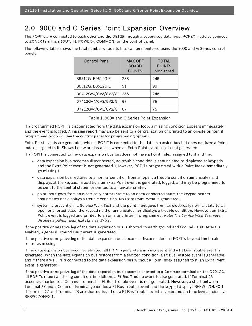
2.0 9000 and G Series Point Expansion Overview The POPITs are connected to each other and the D8125 through a supervised data loop. POPEX modules connect to ZONEX terminals (OUT, IN, POWER+, COMMON) on the control panel.
The following table shows the total number of points that can be monitored using the 9000 and G Series control panels.
Control Panel MAX OFF BOARD POINTS
TOTAL POINTS
Monitored
B9512G, B9512G-E 238 246
B8512G, B8512G-E 91 99
D9412GV4/GV3/GV2/G 238 246
D7412GV4/GV3/GV2/G 67 75
D7212GV4/GV3/GV2/G 67 75
Table 1: 9000 and G Series Point Expansion
If a programmed POPIT is disconnected from the data expansion loop, a missing condition appears immediately and the event is logged. A missing report may also be sent to a central station or printed to an on-site printer, if programmed to do so. See the control panel for programming options.
Extra Point events are generated when a POPIT is connected to the data expansion bus but does not have a Point Index assigned to it. Shown below are instances when an Extra Point event is or is not generated.
If a POPIT is connected to the data expansion bus but does not have a Point Index assigned to it and the:
• data expansion bus becomes disconnected, no trouble condition is annunciated or displayed at keypads and the Extra Point event is not generated. (However, POPITs programmed with a Point Index immediately go missing.)
• data expansion bus restores to a normal condition from an open, a trouble condition annunciates and displays at the keypad. In addition, an Extra Point event is generated, logged, and may be programmed to be sent to the central station or printed to an on-site printer.
• point input goes from an electrically normal state to an open or shorted state, the keypad neither annunciates nor displays a trouble condition. No Extra Point event is generated.
• system is presently in a Service Walk Test and the point input goes from an electrically normal state to an open or shorted state, the keypad neither annunciates nor displays a trouble condition. However, an Extra Point event is logged and printed to an on-site printer, if programmed. Note: The Service Walk Test never displays a points’ electrical state as ‘Extra’.
If the positive or negative leg of the data expansion bus is shorted to earth ground and Ground Fault Detect is enabled, a general Ground Fault event is generated.
If the positive or negative leg of the data expansion bus becomes disconnected, all POPITs beyond the break report as missing.
If the data expansion bus becomes shorted, all POPITs generate a missing event and a Pt Bus Trouble event is generated. When the data expansion bus restores from a shorted condition, a Pt Bus Restore event is generated, and if there are POPITs connected to the data expansion bus without a Point Index assigned to it, an Extra Point event is generated.
If the positive or negative leg of the data expansion bus becomes shorted to a Common terminal on the D7212G, all POPITs report a missing condition. In addition, a Pt Bus Trouble event is also generated. If Terminal 28 becomes shorted to a Common terminal, a Pt Bus Trouble event is not generated. However, a short between Terminal 27 and a Common terminal generates a Pt Bus Trouble event and the keypad displays SERVC ZONEX 1. If Terminal 27 and Terminal 28 are shorted together, a Pt Bus Trouble event is generated and the keypad displays SERVC ZONEX 1.

D8125 | Installation and Operation Guide | 3.0 Non-G 9000 Series Point Expansion .
Bosch Security Systems, Inc. | 12/15 | F01U036298-14 7
The D7212G responds to missing point conditions based on how the points are programmed and which armed state the area is in the point is assigned to. For example, if an interior motion detector point went missing during a disarmed state, a Missing Trouble event is generated. However, if the point went missing while the area was Master Armed, a Missing Alarm event is generated.
2.1 D8125 POPEX and D9127U/T POPIT Modules D9127U/T POPITs use the D8125 POPEX Module to report to the control panel. Each D8125 supports up to 119 POPIT points. The B9512G, D9412GV4, D9412GV3, D9412GV2, and D9412G support two D8125 POPEX Modules.
Points 9 to 127 connect to the first POPEX Module. Points 129 to 247 connect to the second POPEX Module. The control panels reserve Points 128 and 248 for internal use. The control panel only annunciates activity for each POPIT, not each detection device connected to the sensor loop.
All POPIT module enclosures are made of UL Listed fire resistant material. The D9127 Series POPIT Modules includes the D9127T (with magnetic tamper switch) and the D9127U (without tamper). Unless the module is mounted in a tampered enclosure, UL requires the D9127T module for certificated accounts.
2.1.1 Listings
See the Control Panel Approved Applications Compliance Guide or the Installation and System Reference Guide to determine the required equipment and enclosures for the application.
3.0 Non-G 9000 Series Point Expansion The following table shows the total number of points that can be monitored using non-G 9000 Series control panels.
Control Panel MAX OFF BOARD POINTS
TOTAL POINTS Monitored
D9412/D9112 238 246
D9112B1 126 134
D7412/D7212 67 75
D7212B1 40 48
Table 2: Non-9000 and G Series Point Expansion
Each off-board point requires a POPIT module. POPITs connect to supervised two-wire data expansion loops run from POPIT to POPIT throughout the premises. Data expansion loops connect to a D8125 POPEX (Point Of Protection EXpander) module. POPEX module(s) connect to the ZONEX terminals (OUT, IN, POWER+, COMMON) on the control panel.
If a POPIT is disconnected from the expansion loop, a trouble message appears immediately. See the Control Panel Program Entry Guide for programming options.
If you connect a POPIT to the expansion loop that is programmed for a point number that does not appear in the program for the D9412/D9112, it appears as a trouble condition when the data expansion loop restores from a faulted condition. A faulted condition on the data expansion loop includes:
1. Positive leg of the data expansion loop shorted to ground.
2. Negative leg of the data expansion loop shorted to ground.
3. Data expansion loop (positive or negative leg) becomes disconnected.
4. Data expansion loop becomes shorted.
Placing a short on the data expansion loop generates a PT BUS TROUBLE report. The control panel sees all points on the shorted expansion loop as shorted, and responds according to point programming, except for fire points. The fire points respond locally as a trouble condition and transmit missing fire reports if programmed during this condition.

D8125 | Installation and Operation Guide | 3.0 Non-G 9000 Series Point Expansion
8 Bosch Security Systems, Inc. | 12/15 | F01U036298-14
POPIT modules monitor their sensor loops for three conditions, loop normal, loop open, and loop shorted. They report these three conditions to the control panel.
The control panel uses point programming to interpret the sensor loop information reported by the POPITs and make the appropriate system response.
3.2 D8112G1/D8112G2 Point Expansion
3.2.1 D8125 POPEX Module
The D8125 POPEX Module is a hardware accessories for the Bosch Security Systems Zone Expansion (ZONEX) system.
The D8125 POPEX Module is a Point Of Protection EXpander. One or two POPEX Modules can be used to interface zone expansion loops to the D8112G series. Each POPEX Module can monitor up to 63 POPIT Modules, and as many as 126 individual POPIT Modules can be monitored in a ZONEX system with two POPEX Modules. An unlimited number of detection devices can be connected to each POPIT sensor loop; however, annunciation is available only for the sensor loop.
3.2.1.1 Programming
POPEX/POPIT application programs are developed using the Remote Account Manager or the Bosch Security Systems D5200 Bar Code Programmer containing the D8112 Handler. The control panel used for the ZONEX system must be of the D8112“G” Series (referred to in this guide as “D8112G1/G2”). The POPEX/POPIT Modules will not function with the D8112 “E” or “A” Control/Communicators. The D8112G contains the ZONEX firmware, and has expanded memory for custom ZONEX text displays on the Bosch Security Systems D1252A Keypad. (Custom alphanumeric text for each expansion point can be programmed with the D8112 Handler (see the Omegalarm D8112 Zonex System Program/Account Record Sheet). Each POPEX Module is supplied with a D8112 ZONEX System Program/Account Record Sheet, used to record both the ZONEX subhandler program file and the physical location of each POPEX and POPIT Module.
3.2.1.2 Listing
See UL Applications on page 2 to determine the appropriate POPIT module for each application. The POPEX module can be mounted in any D8103, D8108A or D8109 enclosure.
3.2.2 Operation
Each POPIT Module is assigned to report to a D8112G1/G2 control panel “master zone.” The POPIT can transmit three conditions to the D8112G1/G2: sensor loop open, shorted, and normal. The D8112G1/G2 receives the condition signals and interprets them as sensor loop alarm, trouble, or normal, missing POPIT module, or extra POPIT module. The D8112G1/G2 “master zone” loop code program determines the system response to each of these sensor loop conditions. When an event occurs on a POPIT, the D1252A sequences through displays which indicate the type of event.

D8125 | Installation and Operation Guide | 3.0 Non-G 9000 Series Point Expansion .
Bosch Security Systems, Inc. | 12/15 | F01U036298-14 9
3.3 D9124 Point Expansion The D9124 Fire Alarm Control Panel (FACP) is currently shipped with the D9412GLTB control panel. Refer to Section 2.0 9000 and G Series Point Expansion for details regarding POPIT installation.
You can connect up to four data expansion loops to one D8125 input at the motherboard. Data Loops 1 to 4 connect to the D8125 POPEX 1 input on the motherboard (Terminals 11 through 18). Data Loops 5 to 8 connect to the D8125 POPEX 2 input at the motherboard (Terminals 19 through 26).
Verify the proper setting of motherboard jumpers: Make sure the jumpers above Terminals 18 to 24 on the motherboard are in the D8125 position (Figure 1).
3.3.1 POPEX/POPIT Configurations
With the D8125 POPEX Module, you can use:
• D8125 POPEX 1, data loops 1 to 4 (Terminals 11 to 18) on the motherboard.
• install a maximum of 119 POPITs (Points 9 to 127).
• Points 7 and 8 for power supply and initiation circuit supervision. POPITs are not required for these functions.
With an additional D8125 POPEX Module, you can:
• D8125 POPEX 2, data loops 5 to 8 (Terminals 19 to 26) on the motherboard.
• install an additional 119 POPITs (Points 129 to 247) for a maximum of 238 POPITs in the system.
J9
17 18 19 20 21 22 23 24 25 26
J9 J8 J7 J 1 2 J11 J 1 0
P5
Jumpers set in theD8125 position.
Figure 1: D8125 Jumper Setting

D8125 | Installation and Operation Guide | 4.0 Installation
10 Bosch Security Systems, Inc. | 12/15 | F01U036298-14
4.0 Installation 4.1 Installing the enclosure Follow the procedure below to install the D8125 in the enclosure with the control panel or B600.
1. Align the D8125 POPEX module with any of the four mounting locations in the enclosure. See Figure 2.
2. Use the screws provided with the module to secure it in the enclosure.
Save the POPIT Label Sheets: you will use these sheets later to label the POPITs. The D8125 is packaged with two sets of POPIT label sheets. One is marked for use with the D9412/D9112. This set is used for Non G, G, GV2, GV3, GV4, B9512G, and B8512G. The second set of sheets is used for D8112G/G2.
VerticalMountingLocations
(Reserved forDual Phone LineSwitcher Module)
Horizontal MountingLocations
Figure 2: POPEX Installation

D8125 | Installation and Operation Guide | 4.0 Installation .
Bosch Security Systems, Inc. | 12/15 | F01U036298-14 11
4.2 9000 Series and G Series Follow the procedure below to wire one or two D8125 POPEX modules to the 9000 Series, and G Series control panels. For the B9512G, B9512G-E, B8512G, B8512G-E control panels, see the Control Panels Installation and System Reference Guide.
4.2.1 Wiring to the control panel
The B600 Retrofit (ZONEX) module is required to use the D8125 on the B9512G, B9512G-E, B8512G, and B8512G-E control panels.
Remove all power (AC and Battery) before making any connections. Failure to do so may result in personal injury and/or equipment damage.
4.2.2 Disconnecting the Battery and Transformer
1. Disconnect the battery by unhooking the positive (red) battery lead from the battery.
2. Unplug the transformer.
Reversed polarity damages the D8125. Make sure you wire the D8125 AUX and GND terminals to the control panel.
4.2.3 Wiring Procedure
For Points 9 up to Point 127:
1. Connect the GND terminal of the D8125 to the control panel ZONEX COMMON terminal.
2. Connect the OUT terminal of the D8125 POPEX module to ZONEX IN 1.
3. Connect the IN terminal of the D8125 POPEX module to ZONEX OUT 1.
4. Connect the AUX terminal of the D8125 to ZONEX POWER + terminal.
For Points 129 up to Point 247:
1. Connect the GND terminal of the D8125 to the control panel ZONEX COMMON terminal.
2. Connect the OUT terminal of the D8125 POPEX module to ZONEX IN 2.
3. Connect the IN terminal of the D8125 POPEX module to ZONEX OUT 2.
4. Connect the AUX terminal of the D8125 to ZONEX POWER + terminal.
Do not connect more than one D8125 to ZONEX 1 (IN and OUT terminals) or ZONEX 2 (IN and OUT terminals).

D8125 | Installation and Operation Guide | 4.0 Installation
12 Bosch Security Systems, Inc. | 12/15 | F01U036298-14
4.2.4 Wiring POPITs to the Data Expansion Loop
Use one 2-wire data expansion loop or distribute the POPITs on up to three loops. Setting DIP switches on the POPIT modules assigns them to point numbers. Refer to Section 4.2.6 POPIT Module Point Assignments.
Determine the required wire gauge for each data expansion loop using Table 3.
Maximum Length of all Data Expansion Loops Combined
AWG Length ft (m)
22 (0.8) 1800 (549)
20 (1.0) 2890 (881)
18 (1.2) 4600 (1402)
16 (1.5) 7320 (2231)
14 (1.8) 11650 (3551)
Table 3: Data Expansion Loop Wire Specifications
4.2.4.1 Combine data expansion loops
The maximum lengths shown in Table 3 are for all data expansion loops connected to the same POPEX module combined.
Before installing the POPITs, make sure the resistance on the data expansion loop is no more than 40 Ω.
4.2.4.2 Wiring POPITs together
Do NOT connect POPITs to each other in series, or with a T-tap. Doing so may cause random missing POPIT conditions. Follow the procedure below to connect POPITs to one another in parallel. Figure 3 shows a typical configuration.
1. Connect the positive (+) Data terminal from one POPIT to the positive (+) Data terminal on the next POPIT.
2. Connect the negative (-) Data terminal from one POPIT to the negative (-) Data terminal on the next POPIT.
3. Repeat steps 1 and 2 to connect all POPITs to the expansion loop. You don’t need to wire the POPITs in any particular order on the loop. The switch setting on each POPIT assigns it a point number, regardless of its physical location.
Three inch clearance for tampered POPITs: Mount tampered POPIT Modules at least 3.0 in. (76 mm) apart to prevent the tamper magnets from interfering with each other.

D8125 | Installation and Operation Guide | 4.0 Installation .
Bosch Security Systems, Inc. | 12/15 | F01U036298-14 13
4.2.5 Wiring Data Expansion Loops to POPEX Modules
There are two positive (+) and two negative (-) data expansion loop terminals on each POPEX module. Follow the procedure below to connect the data expansion loops to the D8125 POPEX Module (refer to Figure 3). Remember you can only connect a maximum of 119 POPITs to one D8125.
1. Connect the positive (+) Data terminal from the first POPIT on the data expansion loop to one of the D8125 module’s positive (+) terminals.
2. Connect the negative (-) Data terminal from the first POPIT on the data expansion loop to one of the D8125 module’s negative (-) terminals.
4.2.6 POPIT Sensor Loops
The number of normally-open and/or normally-closed detection devices each sensor loop can supervise is limited only by the resistance on the loop. Resistance on each sensor loop must be less than 100 Ω not including the End-of-Line Resistor.
Certain UL and NFPA applications may limit the number of detection devices. Consult the appropriate UL or NFPA standards.
Terminate each POPIT sensor loop with a 33 kΩ End-Of-Line resistor.
Bosch Security Systems recommends you use twisted-pair wire (six twists per foot) in all POPEX/POPIT installations for both the data expansion loop wiring and the POPIT sensor loops. Run wires away from AC sources to prevent AC induction.

D8125 | Installation and Operation Guide | 4.0 Installation
14 Bosch Security Systems, Inc. | 12/15 | F01U036298-14
Figure 3: Connecting the D8125 POPEX to the control panel

D8125 | Installation and Operation Guide | 4.0 Installation .
Bosch Security Systems, Inc. | 12/15 | F01U036298-14 15
4.2.7 POPIT Module Point Assignments
D9127U/T POPITs have seven switches (0-6) that assign the module to a point number. Find POPIT switch settings in the Point Assignment section of the Control Panel Program Record Sheet.
4.2.7.1 POPIT Labels
Two sheets of peel-off POPIT labels are supplied with the D8125 POPEX module. Use the sheet marked Bank1 for Points 9 to 127. Use the sheet marked Bank2 or Points 129 to 247.
Each label has two parts. Place the smaller part, with just the point number on it, on the chip. Place the larger part with the switch settings on the base of the POPIT. Set the switches and cover the POPIT.
Do not program two POPITs for the same point number. After you program all the points, perform a service walk test. The Troubleshooting section of this document contains instructions for performing a service walk test. If a point does not test, check the programming for a duplicate address switch settings.
3.2.7.2 Three inch clearance for tampered POPITs
Mount tampered POPIT modules at least 3.0 in. (76 mm) apart to prevent the tamper magnets from interfering with each other.
4.3 D8112G1/G2
4.3.1 Wiring to the control panel
Remove all power (AC and Battery) before making any connections. Failure to do so may result in personal injury and/or equipment damage.
4.3.1.1 Disconnecting the Battery and Transformer
1. Disconnect the battery by unhooking the positive (red) battery lead from the battery.
2. Unplug the transformer.
Reversed polarity damages the D8125. Make sure you correctly wire the D8125 AUX and GND terminals to the control panel.
4.3.1.2 Wiring Procedure
1. Connect D8112G1/G2 Terminal 4 to the POPEX GND terminal (see Figure 4).
2. Connect D8112G1/G2 Terminal 3 to the POPEX AUX terminal.
3. Connect D8112G1/G2 Terminal 31 to the POPEX IN terminal.
4. Installing only one POPEX:
Horizontal Mode: Connect the POPEX OUT terminal to the D8112G1/G2 Terminal 28; then go to step 6.
Vertical Mode: Connect the POPEX OUT terminal to the D8112G1/G2 Terminal 27 or 28; then go to step 6. If an Independent Zone Control (IZC) (D279 or D268/D269) is used, it is recommended that the POPEX be connected to Terminal 27 on the D8112G2 and the IZC be attached to Zone 1, 2, 3, or 4. This will allow you to maximize your COMEX ID Groups 6-8. For information concerning COMEX refer to the COMEX Program Entry Guide (P/N: 74-05073-000).
Note: If the vertical mode is used, POPEX #2 can be installed without installing POPEX #1.

D8125 | Installation and Operation Guide | 4.0 Installation
16 Bosch Security Systems, Inc. | 12/15 | F01U036298-14
Step 5 is for POPEX #2 only.
5. Installing two POPEX Modules (in the horizontal or vertical mode): Repeat steps 1 through 3 for POPEX #2; then connect D8112G terminal 27 to POPEX #2 OUT terminal.
Before powering up the D8112, check terminals 3 and 4 for correct wiring. Reverse polarity WILL damage the POPEX module.
6. Reconnect AC and DC power to the D811G1/G2.
4.3.2 POPIT Module Installation
4.3.2.1 Wiring POPITs to the Expansion Loop
The zone expansion loop is a two-conductor wire interconnecting all POPIT Modules assigned to a single POPEX (see Figure 4). Up to three zone expansion loops can be connected to one D8125 when using unshielded cable. The required wire gauge for the zone expansion loop(s) (up to three max.) can be determined using Table 4. When using unshielded cable each zone expansion loop can be up to the distance shown in Table 4.
Hint: AC induction or RF interference may occur when a ZONEX system is installed in or near the following:
• Radio station transmitter site or other broadcast station
• Ham radio transmitter site
• Computer network system
• Heavy machinery and motors
• PBX telephone system
• Welding shop
• High voltage electrical equipment or transformers
• Public service (police, fire department, etc.) using radio communications
• When wires must be run close to electrical lines, fluorescent fixtures or telephone cabling
POPIT Modules do not need to be wired in any particular order on the zone expansion loop. A switch setting on each POPIT (see POPIT Module Assignments on page 19) identifies the point of protection, regardless of its physical location.
The POPIT modules should be connected to one another in parallel (see Figure 2).
D8125 | Installation and Operation Guide | 4.0 Installation .
Bosch Security Systems, Inc. | 12/15 | F01U036298-14 17
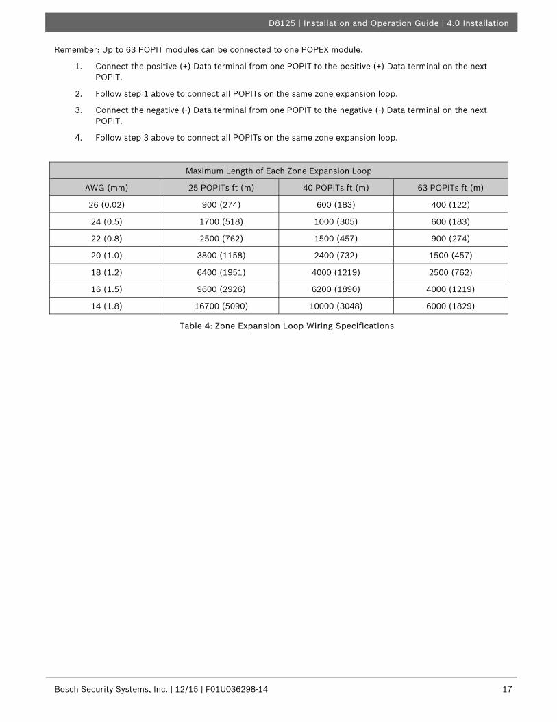
Remember: Up to 63 POPIT modules can be connected to one POPEX module.
1. Connect the positive (+) Data terminal from one POPIT to the positive (+) Data terminal on the next POPIT.
2. Follow step 1 above to connect all POPITs on the same zone expansion loop.
3. Connect the negative (-) Data terminal from one POPIT to the negative (-) Data terminal on the next POPIT.
4. Follow step 3 above to connect all POPITs on the same zone expansion loop.
Maximum Length of Each Zone Expansion Loop
AWG (mm) 25 POPITs ft (m) 40 POPITs ft (m) 63 POPITs ft (m)
26 (0.02) 900 (274) 600 (183) 400 (122)
24 (0.5) 1700 (518) 1000 (305) 600 (183)
22 (0.8) 2500 (762) 1500 (457) 900 (274)
20 (1.0) 3800 (1158) 2400 (732) 1500 (457)
18 (1.2) 6400 (1951) 4000 (1219) 2500 (762)
16 (1.5) 9600 (2926) 6200 (1890) 4000 (1219)
14 (1.8) 16700 (5090) 10000 (3048) 6000 (1829)
Table 4: Zone Expansion Loop Wiring Specifications

D8125 | Installation and Operation Guide | 4.0 Installation
18 Bosch Security Systems, Inc. | 12/15 | F01U036298-14

D8125 | Installation and Operation Guide | 4.0 Installation .
Bosch Security Systems, Inc. | 12/15 | F01U036298-14 19
Figure 4: D8112G1/G2 POPEX and POPIT Module Installation
4.3.3.2 Wiring POPITs to a POPEX Module
Two positive (+) and two negative (-) zone expansion loop terminals are provided on each POPEX Module for wiring convenience.
When using two POPEX Modules, each module must have its own expansion loop (e.g., POPIT Modules assigned to POPEX #1 cannot be placed on the POPEX #2 Zone Expansion Loop). Limit your zone expansion loop coming back to the POPEX module, to a maximum of three data runs.
Note: Up to two POPEX modules can be connected to one D8112G1/G2 control panel.
When connecting the zone expansion loop to the POPEX Module, follow the steps below:
1. Connect the positive (+) wire from the zone expansion loop to the POPEX Module positive (+) loop input.
2. Connect the negative (-) wire from the zone expansion loop to the POPEX Module negative (-) loop input.
4.3.3.3 Wiring POPIT Sensor Loop
Each POPIT Module can supervise an unlimited number of detection devices on its two-wire sensor loop. Each POPIT can monitor normally-open devices wired in parallel, normally-closed devices wired in series, or a combination of devices wired in parallel and series. Open, closed, and normal circuit conditions can be detected and transmitted to the D8112G. A system cannot be armed normally if any of the sensor loops are faulted. (A system with loop faults can be force-armed, however.)
All POPIT sensor loops must be terminated with a 33 kΩ End-Of-Line supplied with each POPIT module.
The maximum length of 22 AWG (0.8 mm) cable used for each sensor loop is determined by voltage drop. Bosch Security Systems recommends the use of twisted-pair wire in all POPEX-POPIT installations. If a noisy or unstable environment is suspected, or if a long sensor loop wire run is used, the cable must be shielded against AC induction. Refer to the AC induction hint in Wiring POPITs to the Expansion Loop in this section for more information.
4.3.4 POPIT Module Assignments
Six switches provided on each POPIT assign the module to a D8112G1/G2 master zone. These switches provide a unique expansion point identification for each POPIT Module. In Table 5 and Table 6, numbers indicate which switches must be placed in the ON position for each POPIT. Switches indicated by a dash (-) must be placed in the OFF position.
Note: The points of protection must be assigned sequentially. Example: If 12 points of protection are assigned to Master Zone 4, the 12 POPITs must have switch settings corresponding to I.D. Codes 401 through 412.

D8125 | Installation and Operation Guide | 4.0 Installation
20 Bosch Security Systems, Inc. | 12/15 | F01U036298-14
4.3.5 POPIT Labels
Four sets of POPIT I.D. labels are provided with each POPEX Module. Each set is associated with either POPEX #1 (PX 1) or POPEX #2 (PX 2), and with either the horizontal or vertical mode. In every POPEX/POPIT installation, at least two sets of these labels are NOT used. For example, when installing a vertical mode ZONEX system, all horizontal mode labels should be discarded. If the ZONEX system uses only one POPEX Module, discard all the POPEX #2 labels.
Do NOT mix the horizontal and vertical labels. The system can be programmed for only one mode. Do NOT use both types of labels in the same ZONEX system. A label should be attached to each POPIT Module when the switches are set, thereby preventing duplicate switch settings. Do NOT place labels on POPIT covers, attach them directly to the circuit board. This will help to prevent points from being labeled or set incorrectly.
Here is an example of a POPIT display:
When an event occurs, the POPIT sends a signal to the control panel via the POPEX Module. The D8112G1/G2 decodes the event signal, displays an event status code, and initiates the appropriate system response. The D1252A Keypad can be programmed to display two types of information: programmable and standard. Instructions for programming D1252A Keypad displays are found in Program Items 105 through 120 in the Omegalarm D8112:MAIN Program Entry Guide and the Omegalarm D8112:PTEXT Program Entry Guide.

D8125 | Installation and Operation Guide | 4.0 Installation .
Bosch Security Systems, Inc. | 12/15 | F01U036298-14 21
ZN101S2
Memory of Previous Events: The D1252Adisplays a memory code to annunciate eventswhich have taken place since the system waslast armed.
1 = Alarm Memory2 = Trouble Memory3 = Alarm and Trouble Memory4 = Missing Memory5 = Alarm Memory and Missing6 = Trouble Memory and Missing7 = Alarm & Trouble Memory Missing
Current State of Sensor Loop
O = Sensor loop electrically openor grounded
S = Sensor loop electricallyshorted
(blank) = Sensor loop electrically normalM = Missing POPIT Module (POPIT
is programmed to be in thesystem, but is not respondingto polling)
X = Extra POPIT Module (POPIT isresponding to polling, but isnot programmed to be in thesystem
POPIT Expansion Point: This is theidentification of the Module transmitting theevent (ex., point 01).
Master Zone Number: The D9112G masterzone number assigned to the POPIT (ex. masterzone 100).
Zone: This identifies the display as a POPITstatus display.
Figure 5: Explanation of POPIT Display

D8125 | Installation and Operation Guide | 4.0 Installation
22 Bosch Security Systems, Inc. | 12/15 | F01U036298-14
4.3.5.1 POPEX/POPIT Configurations
Two configurations, horizontal (Table 5) and vertical (Table 6) are used to organize points of protection. Both modes provide the ZONEX system with the maximum of 126 points of protection. The two Zone Expansion terminals are typically used to group POPITs in a ZONEX system.
The selection of the mode is significant when only one POPEX Module is installed. With one POPEX module, an application which requires no more than eight points of protection in as many as eight zones can use the horizontal mode (Table 5). An application which requires more than eight points of protection in no more than four zones can use the vertical mode (Table 5) displays, refer to the D1252A Security System User’s Guide (P/N: 71-04415-000). If two POPEX Modules are installed, all points of protection are available. Some of the differences between the modes are listed below:
In the horizontal mode with one POPEX Module:
• All eight zones of the D8112G1/G2 can be used in the ZONEX system.
• Up to eight POPITs can be assigned to D8112G1/G2 Master Zones 1-7.
• A maximum of seven POPITs can be assigned to D8112G1/G2 Master Zone 8.
• A maximum of 63 POPITs can be installed.
In the horizontal mode with two POPEX Modules:
• Up to 16 POPITs can be assigned to D8112G1/G2 Master Zones 1-7.
• A maximum of 14 POPITs can be assigned to D8112G1/G2 Master Zone 8 (7 POPITs on POPEX #1 and 7 POPITs on POPEX #2).
• POPEX #1 assigns a maximum of 8 POPITs to a D8112G1/G2 zone (ex., Points 101-108).
• POPEX #2 assigns an additional 8 POPITs maximum, to a D8112G1/G2 zone (ex., Points 109-116).
• A maximum of 126 POPITs can be installed.
In the vertical mode with one POPEX Module:
• Only four zones of the D8112G1/G2 can be used in the ZONEX system.
• Zones must be used in groups (Zones 1 through 4, or Zones 5 through 8).
• Up to 16 POPITs can be assigned to D8112G1/G2 master Zones 1-3 or 5-7.
• A maximum of 15 POPITs can be assigned to D8112G1/G2 Zones 4 and 8.
• A maximum of 63 POPITs can be installed.
In the vertical mode with two POPEX Modules:
• Up to 16 POPITs can be assigned to D8112G1/G2 Master Zones 1-3 or 5-7.
• POPEX #1 assigns a maximum of 16 POPITs to D8112G1/G2 zones 1 through 3.
• POPEX #2 assigns a maximum of 16 POPITs to D8112G1/G2 Zones 5 through 7.
• Only 15 POPITs can be assigned to D8112G1/G2 Zones 4 and 8.
• A maximum of 126 POPITs can be installed.

D8125 | Installation and Operation Guide | 4.0 Installation .
Bosch Security Systems, Inc. | 12/15 | F01U036298-14 23
Table 5 and Table 6 display all POPIT assignment switch settings for both the horizontal and vertical modes (e.g., 1 2 3 4 - -). Numbers 1 through 6 indicate switches 1-6 on the POPIT Module. The dash (-) indicates a switch is in the OFF or open position. These switches assign each point of protection to a master zone (refer to Section 4.2.6 POPIT Module Point Assignments for switch settings). Table 5 and Table 6 indicate the maximum number of POPITs that can be assigned to each D8112G1/G2 master zone, with one and two POPEX Modules.
Below the switch setting is the I.D. code (e.g., ZN 104) for each POPIT. The master zone and expansion point (point of protection) are used to cross-reference the POPIT Module to an event displayed on the D1252A Keypad. For example, in the I.D. code ZN104, “ZN1” indicates that the POPIT is assigned to master zone 100 of the D8112G1/G2 control panel, and “04” indicates that the POPIT reports as expansion point #4.

D8125 | Installation and Operation Guide | 4.0 Installation
24 Bosch Security Systems, Inc. | 12/15 | F01U036298-14
HORIZONTAL MODE – POPEX AND POPIT MODULESD8112
MASTERZONE 1
D8112MASTERZONE 2
D8112MASTERZONE 3
D8112MASTERZONE 4
D8112MASTERZONE 5
D8112MASTERZONE 6
D8112MASTERZONE 7
D8112MASTERZONE 8
1 2 3 4 5 6ZN 101
1 2 - 4 5 6ZN 201
1 - 3 4 5 6ZN 301
1 - - 4 5 6ZN 401
- 2 3 4 5 6ZN 501
- 2 - 4 5 6ZN 601
- - 3 4 5 6ZN 701
- - - 4 5 6ZN 801
1 2 3 4 5 -ZN 102
1 2 - 4 5 -ZN 202
1 - 3 4 5 -ZN 302
1 - - 4 5 -ZN 402
- 2 3 4 5 -ZN 502
- 2 - 4 5 -ZN 602
- - 3 4 5 -ZN 702
- - - 4 5 -ZN 802
1 2 3 4 - 6ZN 103
1 2 - 4 - 6ZN 203
1 - 3 4 - 6ZN 303
1 - - 4 - 6ZN 403
- 2 3 4 - 6ZN 503
- 2 - 4 - 6ZN 603
- - 3 4 - 6ZN 703
- - - 4 - 6ZN 803
1 2 3 4 - -ZN 104
1 2 - 4 - -ZN 204
1 - 3 4 - -ZN 304
1 - - 4 - -ZN 404
- 2 3 4 - -ZN 504
- 2 - 4 - -ZN 604
- - 3 4 - -ZN 704
- - - 4 - -ZN 804
1 2 3 - 5 6ZN 105
1 2 - - 5 6ZN 205
1 - 3 - 5 6ZN 305
1 - - - 5 6ZN 405
- 2 3 - 5 6ZN 505
- 2 - - 5 6ZN 605
- - 3 - 5 6ZN 705
- - - - 5 6ZN 805
1 2 3 - 5 -ZN 106
1 2 - - 5 -ZN 206
1 - 3 - 5 -ZN 306
1 - - - 5 -ZN 406
- 2 3 - 5 -ZN 506
- 2 - - 5 -ZN 606
- - 3 - 5 -ZN 706
- - - - 5 -ZN 806
1 2 3 - - 6ZN 107
1 2 - - - 6ZN 207
1 - 3 - - 6ZN 307
1 - - - - 6ZN 407
- 2 3 - - 6ZN 507
- 2 - - - 6ZN 607
- - 3 - - 6ZN 707
- - - - - 6ZN 807
PO
PE
X 1
(D
8112
G1/
G2
TE
RM
INA
L 28
)
1 2 3 - - -ZN 108
1 2 - - - -ZN 208
1 - 3 - - -ZN 308
1 - - - - -ZN 408
- 2 3 - - -ZN 508
- 2 - - - -ZN 608
- - 3 - - -ZN 708
NOTUSED
1 2 3 4 5 6ZN 109
1 2 - 4 5 6ZN 209
1 - 3 4 5 6ZN 309
1 - - 4 5 6ZN 409
- 2 3 4 5 6ZN 509
- 2 - 4 5 6ZN 609
- - 3 4 5 6ZN 709
- - - 4 5 6ZN 809
1 2 3 4 5 -ZN 110
1 2 - 4 5 -ZN 210
1 - 3 4 5 -ZN 310
1 - - 4 5 -ZN 410
- 2 3 4 5 -ZN 510
- 2 - 4 5 -ZN 610
- - 3 4 5 -ZN 710
- - - 4 5 -ZN 810
1 2 3 4 - 6ZN 111
1 2 - 4 - 6ZN 211
1 - 3 4 - 6ZN 311
1 - - 4 - 6ZN 411
- 2 3 4 - 6ZN 511
- 2 - 4 - 6ZN 611
- - 3 4 - 6ZN 711
- - - 4 – 6ZN 811
1 2 3 4 - -ZN 112
1 2 - 4 - -ZN 212
1 - 3 4 - -ZN 312
1 - - 4 - -ZN 412
- 2 3 4 - -ZN 512
- 2 - 4 - -ZN 612
- - 3 4 - -ZN 712
- - - 4 - -ZN 812
1 2 3 - 5 6ZN 113
1 2 - - 5 6ZN 213
1 - 3 - 5 6ZN 313
1 - - - 5 6ZN 413
- 2 3 - 5 6ZN 513
- 2 - - 5 6ZN 613
- - 3 - 5 6ZN 713
- - - - 5 6ZN 813
1 2 3 – 5 -ZN 114
1 2 - - 5 -ZN 214
1 - 3 - 5 -ZN 314
1 - - - 5 -ZN 414
- 2 3 - 5 -ZN 514
- 2 - - 5 -ZN 614
- - 3 - 5 -ZN 714
- - - - 5 -ZN 814
1 2 3 - - 6ZN 115
1 2 - - - 6ZN 215
1 - 3 - - 6ZN 315
1 - - - - 6ZN 415
- 2 3 - - 6ZN 515
- 2 - - - 6ZN 615
- - 3 - - 6ZN 715
- - - - - 6ZN 815
PO
PE
X 1
(D
8112
G1/
G2
TE
RM
INA
L 29
)
1 2 3 - - -ZN 116
1 2 - - - -ZN 216
1 - 3 - - -ZN 316
1 - - - - -ZN 416
- 2 3 - - -ZN 516
- 2 - - - -ZN 616
- - 3 - - -ZN 716
NOTUSED
POPEX #1(D8112G1/G2 TERM 28)
8 8 8 8 8 8 8 7 63
POPEX #1(D8112G1/G2 TERM 28)
8 8 8 8 8 8 8 7 63
Table 5: D8112G1/G2 Horizontal Mode - POPEX and POPIT Modules

D8125 | Installation and Operation Guide | 4.0 Installation .
Bosch Security Systems, Inc. | 12/15 | F01U036298-14 25
VERTICAL MODE – POPEX AND POPIT MODULESPOPEX 1 (D8112G1/G2 TERMINAL 28) POPEX 2 (D8112G1/G2 TERMINAL 27)
D8112MASTERZONE 1
D8112MASTERZONE 2
D8112MASTERZONE 3
D8112MASTERZONE 4
D8112MASTERZONE 5
D8112MASTERZONE 6
D8112MASTERZONE 7
D8112MASTERZONE 8
1 2 3 4 5 6ZN 101
1 - 3 4 5 6ZN 201
- 2 3 4 5 6ZN 301
- - 3 4 5 6ZN 401
1 2 3 4 5 6ZN 501
1 - 3 4 5 6ZN 601
- 2 3 4 5 6ZN 701
- - 3 4 5 6ZN 801
1 2 3 4 5 -ZN 102
1 - 3 4 5 -ZN 202
- 2 3 4 5 -ZN 302
- - 3 4 5 -ZN 402
1 2 3 4 5 -ZN 502
1 - 3 4 5 -ZN 602
- 2 3 4 5 -ZN 702
- - 3 4 5 -ZN 802
1 2 3 4 - 6ZN 103
1 - 3 4 - 6ZN 203
- 2 3 4 - 6ZN 303
- - 3 4 - 6ZN 403
1 2 3 4 - 6ZN 503
1 - 3 4 - 6ZN 603
- 2 3 4 - 6ZN 703
- - 3 4 - 6ZN 803
1 2 3 4 - -ZN 104
1 - 3 4 - -ZN 204
- 2 3 4 - -ZN 304
- - 3 4 - -ZN 404
1 2 3 4 - -ZN 504
1 - 3 4 - -ZN 604
- 2 3 4 - -ZN 704
- - 3 4 - -ZN 804
1 2 3 - 5 6ZN 105
1 - 3 - 5 6ZN 205
- 2 3 - 5 6ZN 305
- - 3 - 5 6ZN 405
1 2 3 - 5 6ZN 505
1 - 3 - 5 6ZN 605
- 2 3 - 5 6ZN 705
- - 3 - 5 6ZN 805
1 2 3 - 5 -ZN 106
1 - 3 - 5 -ZN 206
- 2 3 - 5 -ZN 306
- - 3 - 5 -ZN 406
1 2 3 - 5 -ZN 506
1 - 3 - 5 -ZN 606
- 2 3 - 5 -ZN 706
- - 3 - 5 -ZN 806
1 2 3 - - 6ZN 107
1 - 3 - - 6ZN 207
- 2 3 - - 6ZN 307
- - 3 - - 6ZN 407
1 2 3 - - 6ZN 507
1 - 3 - - 6ZN 607
- 2 3 - - 6ZN 707
- - 3 - - 6ZN 807
1 2 3 - - -ZN 108
1 - 3 - - -ZN 208
- 2 3 - - -ZN 308
- - 3 - - -ZN 408
1 2 3 - - -ZN 508
1 - 3 - - -ZN 608
- 2 3 - - -ZN 708
- - 3 - - -ZN 808
1 2 - 4 5 6ZN 109
1 - - 4 5 6ZN 209
- 2 - 4 5 6ZN 309
- - - 4 5 6ZN 409
1 2 - 4 5 6ZN 509
1 - - 4 5 6ZN 609
- 2 - 4 5 6ZN 709
- - - 4 5 6ZN 809
1 2 - 4 5 -ZN 110
1 - - 4 5 -ZN 210
- 2 - 4 5 -ZN 310
- - - 4 5 -ZN 410
1 2 - 4 5 -ZN 510
1 - - 4 5 -ZN 610
- 2 - 4 5 -ZN 710
- - - 4 5 -ZN 810
1 2 - 4 - 6ZN 111
1 - - 4 - 6ZN 211
- 2 - 4 - 6ZN 311
- - - 4 - 6ZN 411
1 2 - 4 - 6ZN 511
1 - - 4 - 6ZN 611
- 2 - 4 - 6ZN 711
- - - 4 - 6ZN 811
1 2 - 4 - -ZN 112
1 - - 4 - -ZN 212
- 2 - 4 - -ZN 312
- - - 4 - -ZN 412
1 2 - 4 - -ZN 512
1 - - 4 - -ZN 612
- 2 - 4 - -ZN 712
- - - 4 - -ZN 812
1 2 - - 5 6ZN 113
1 - - - 5 6ZN 213
- 2 - - 5 6ZN 313
- - - - 5 6ZN 413
1 2 - - 5 6ZN 513
1 - - - 5 6ZN 613
- 2 - - 5 6ZN 713
- - - - 5 6ZN 813
1 2 - - 5 -ZN 114
1 - - - 5 -ZN 214
- 2 - - 5 -ZN 314
- - - - 5 -ZN 414
1 2 - - 5 -ZN 514
1 - - - 5 -ZN 614
- 2 - - 5 -ZN 714
- - - - 5 -ZN 814
1 2 - - - 6ZN 115
1 - - - - 6ZN 215
- 2 - - - 6ZN 315
- - - - - 6ZN 415
1 2 - - - 6ZN 515
1 - - - - 6ZN 615
- 2 - - - 6ZN 715
- - - - - 6ZN 815
1 2 - - - -ZN 116
1 - - - - -ZN 216
- 2 - - - -ZN 316
NOTUSED
1 2 - - - -ZN 516
1 - - - - 6ZN 616
- 2 - - - -ZN 716
NOTUSED
POPEX #1(D8112G1/G2 TERM 28)
16 16 16 16 N/A N/A N/A N/A 63
POPEX #1(D8112G1/G2 TERM 27)
N/A N/A N/A N/A 16 16 16 16 63
Table 6: D8112G1/G2 Vertical Mode - POPEX and POPIT Modules

D8125 | Installation and Operation Guide | 4.0 Installation
26 Bosch Security Systems, Inc. | 12/15 | F01U036298-14
4.3.6 POPIT Displays The status of each POPIT Module is transmitted to the D8112G1/G2 control panel. The status is recorded and held in the D8112G1/G2 memory buffer until the system is armed and the exit delay time has expired. The D1252A Keypad displays both the current status and the event memory with a special code. 4.3.6.1 Alarm Condition Displays When an event occurs in the system (an open or shorted loop) that the D8112G1/G2 interprets as an alarm, the system initiates an alarm response, and the D1252A sequences through the following displays:
4.3.6.2 Fault Condition Displays When a loop fault occurs, the following displays can appear on the D1252A (rows of stars separate displays pertaining to individual points of protection): 4.3.6.3 Trouble Condition Displays When a loop trouble occurs, the following displays can appear on the D1252A (rows of stars separate displays pertaining to individual points of protection):

D8125 | Installation and Operation Guide | 4.0 Installation .
Bosch Security Systems, Inc. | 12/15 | F01U036298-14 27
4.3.7. Central Station Reports
4.3.7.1 Pulse and BFSK Reporting
When a POPIT initiates an alarm or trouble report, the D8112G/G2 transmits the reports indicating the D8112 master zone tripped. Two POPIT reports to the central station (in addition to alarm, trouble, and restoral reports for each master zone) are supported.
TROUBLE ZONE D indicates a “missing” POPIT condition.
RESTORAL ZONE D indicates that a “missing” POPIT condition has been resolved.
These reports may be followed by a TROUBLE ZONE # or RESTORAL ZONE # report, which indicates the master zone assignment of the missing POPIT.
4.3.7.2 Modem II Reporting
Only D8112G2 supports expanded POPIT reports (such as POPIT alarm reports) using Modem II format reporting.
Trouble Reports
When ZONEX is used on a 24 hour master zone or a controlled point in the disarmed state, and a missing condition occurs, the following report is printed out on the D6500 Receiver tape:
ACCT 1234 TROUBLE ZN D
ACCT 1234 TROUBLE* ZN 101
* Indicates that this point is “Missing”
Restoral Reports
When the point is restored from the missing condition, the following report will be printed out on the D6500 Receiver tape:
ACCT 1234 RESTORAL ZN D
ACCT 1234 RESTORAL ZN 101
When multiple points on the same master zone go into any trouble condition, all of the points on the master zone must be returned to normal before individual restoral reports are sent to the D6500 receiver. A RESTORAL ZONE D will, however, be sent when the backbone itself has restored.
Missing Reports (Multiple)
If multiple points assigned to the same master zone go into a missing condition while in the disarmed state, the following reports are printed out on the D6500 Receiver tape:
ACCT 1234 TROUBLE* ZN D
ACCT 1234 TROUBLE* ZN 103
ACCT 1234 TROUBLE* ZN 102
ACCT 1234 TROUBLE* ZN 101
* Indicates that this point is “Missing”
Armed Controlled Zone Points
If the D8112G2 is armed, a missing report would be printed out on the D6500 Receiver tape as follows:
ACCT 1234 TROUBLE ZN D
ACCT 1234 ALARM* ZN 101
* Indicates that this point is “Missing”
When multiple points on the same master zone go into any alarm condition, all of the points on the master zone must be returned to normal before individual restoral reports are sent to the D6500 receiver. A RESTORAL ZONE D will, however, be sent when the expansion loop itself has restored.
A complete list of reports received by the D6500 Receiver can be found in the D6500 Report Directory (P/N: 4998132019).

D8125 | Installation and Operation Guide | 4.0 Installation
28 Bosch Security Systems, Inc. | 12/15 | F01U036298-14
4.3.8 Local Status Test
4.3.8.1 Operation
While disarmed, the security system status can be checked by entering [COMMAND 44] at the D1252A Keypad. This command also initiates a system walk test (described in the D1252A Security System User’s Guide, P/N: 71-04415-000) as part of the status test. Each point of protection is polled as the D8112G1/G2 interrogates its eight master zones. The D1252A Keypad displays two small “bird feet” (^^) that “hop” (scroll) across the screen to indicate that a master zone is under interrogation.
If the D8112G1/G2 contains an event (either a current event or an event in memory), the “bird feet” display is replaced by the event held in memory (see Section 4.3.6 POPIT Displays). Events begin to accumulate each time the system is armed. System events can be cleared from the D8112G1/G2 memory by arming the system and allowing the exit time to expire or disable/restart the D8112G1/G2.
If a programmed point of protection does not respond to the polling interrogation, a “missing” POPIT condition is displayed (see Section 4.3.6 POPIT Displays). An “extra” POPIT display indicates that the ZONEX program does not recognize a POPIT Module transmission. Press any key on the D1252A Keypad to end the test.
3.3.8.2 Missing and Extra POPIT Modules
“Missing” and “extra” POPIT conditions are typically caused by installation or programming errors. In a properly functioning system, all POPIT Modules which are installed are assigned to the appropriate master zone in the ZONEX sub-handler program file. Figure 6 illustrates a system with six POPITs assigned to each of the first five master zones.
2.5 Z1POINTS 6
2.12 Z8POINTS 00
PROGRAMMED
2.6 Z2POINTS 6
2.7 Z3POINTS 6
2.8 Z4POINTS 6
2.9 Z5POINTS 6
2.10 Z6POINTS 00
2.11 Z7POINTS 00
MASTER ZONE 1: 6
MASTER ZONE 2: 6
MASTER ZONE 3: 6
MASTER ZONE 4: 6
MASTER ZONE 5: 6
INSTALLED
Figure 6: Operative ZONEX System
Figure 7 illustrates a system with six POPITs assigned in programming to each of five master zones in the ZONEX program file, and only five POPITs installed for Master Zone 5. A “missing” POPIT condition will be displayed when COMMAND 44 is entered in the D1252A. If the POPIT is assigned to a D8112G1/G2 protective zone programmed for controlled zone response (burglary) and the D8112G1/G2 is armed, the “missing” POPIT condition causes a system alarm. If the D8112G1/G2 is disarmed, the system goes into a trouble condition. If the POPIT is assigned to a D8112G1/G2 protective zone programmed for 24 hour zone response (fire, panic, holdup, etc.) the “missing” POPIT indicates a trouble condition.
MISSINGPOPIT
2.5 Z1POINTS 6
2.12 Z8POINTS 00
PROGRAMMED
2.6 Z2POINTS 6
2.7 Z3POINTS 6
2.8 Z4POINTS 6
2.9 Z5POINTS 6
2.10 Z6POINTS 00
2.11 Z7POINTS 00
MASTER ZONE 1: 6
MASTER ZONE 2: 6
MASTER ZONE 3: 6
MASTER ZONE 4: 6
MASTER ZONE 5: 5
INSTALLED
Figure 7: Missing POPIT

D8125 | Installation and Operation Guide | 4.0 Installation .
Bosch Security Systems, Inc. | 12/15 | F01U036298-14 29
Figure 8 illustrates a system with six POPITs assigned in programming to each of five master zones, and seven POPITs installed for master zone 5. An “extra” POPIT condition will be displayed when [COMMAND 44] is entered at the D1252A. The “extra” POPIT condition is annunciated only through the D1252A Keypad, and does not initiate a report to the central station.
EXTRAPOPIT
2.5 Z1POINTS 6
2.12 Z8POINTS 00
PROGRAMMED
2.6 Z2POINTS 6
2.7 Z3POINTS 6
2.8 Z4POINTS 6
2.9 Z5POINTS 6
2.10 Z6POINTS 00
2.11 Z7POINTS 00
MASTER ZONE 1: 6
MASTER ZONE 2: 6
MASTER ZONE 3: 6
MASTER ZONE 4: 6
MASTER ZONE 5: 7
INSTALLED
Figure 8: Extra POPIT
If six POPITs are assigned in programming to each of five master zones, and one POPIT has erroneous switch settings (see Figure 9), Master Zone 5 appears to have only five POPITs installed, and Master Zone 7 (which has no POPITs assigned in programming) appears to have one POPIT installed. Both “missing” and “extra” POPIT conditions will be displayed on the D1252A.
2.5 Z1POINTS 6
2.12 Z8POINTS 00
PROGRAMMED
2.6 Z2POINTS 6
2.7 Z3POINTS 6
2.8 Z4POINTS 6
2.9 Z5POINTS 6
2.10 Z6POINTS 00
2.11 Z7POINTS 00
MASTER ZONE 1: 6
MASTER ZONE 2: 6
MASTER ZONE 3: 6
MASTER ZONE 4: 6
MASTER ZONE 5: 5MISSINGPOPIT
MASTER ZONE 7: 1EXTRAPOPIT
INSTALLED
Figure 9: POPIT Switch Setting Error
Figure 10 also displays a system containing one POPIT with erroneous switch settings. Both “missing” and “extra” POPIT conditions will be displayed on the D1252A after entering a [Command 44].
2.5 Z1POINTS 6
2.12 Z8POINTS 00
PROGRAMMED
2.6 Z2POINTS 6
2.7 Z3POINTS 6
2.8 Z4POINTS 6
2.9 Z5POINTS 6
2.10 Z6POINTS 00
2.11 Z7POINTS 00
MASTER ZONE 1: 6
MASTER ZONE 2: 6
MASTER ZONE 3: 6
MASTER ZONE 4: 5
MASTER ZONE 5: 7
MISSINGPOPIT
EXTRAPOPIT
INSTALLED
Figure 10: POPIT Switch Setting Error

D8125 | Installation and Operation Guide | 4.0 Installation
30 Bosch Security Systems, Inc. | 12/15 | F01U036298-14
If an extra POPIT is installed the system will indicate that it is READY TO ARM. The “extra” POPIT message will only be displayed when [COMMAND 44] is entered at the D1252A (see Figure 11). Non-normal conditions in all POPITs assigned to the master zone with the extra POPIT may not be correctly reported as opens or shorts to the D8112G. If all POPITs assigned to this master are normal, however, a normal condition will be correctly reported.
EXTRA POPIT(not displayed)
2.5 Z1POINTS 6
2.12 Z8POINTS 00
PROGRAMMED
2.6 Z2POINTS 6
2.7 Z3POINTS 6
2.8 Z4POINTS 6
2.9 Z5POINTS 6
2.10 Z6POINTS 00
2.11 Z7POINTS 00
MASTER ZONE 1: 6
MASTER ZONE 2: 6
MASTER ZONE 3: 6
MASTER ZONE 4: 6
MASTER ZONE 5: 7
INSTALLED
Figure 11: Extra POPIT Installed
Installations described in Figure 10 and Figure 11 are similar, Figure 10 will display the “extra” POPIT condition because all POPIT switch settings assigned to master zone 5 are unique. In Figure 12, the “extra” POPIT condition is not displayed due to the duplication of switch settings.
If a POPIT is assigned to the wrong master zone, and it has the same switch settings as a POPIT in that master zone, the “missing” POPIT condition will be indicated but the “extra” POPIT will NOT be displayed (see Figure 12). Although the installations described in Figure 10 and Figure 12 are similar, Figure 12 will display the “extra” POPIT condition because all POPIT switch settings assigned to master zone 5 are unique. In Figure 12, the “extra” POPIT condition is not displayed due to the duplication of switch settings.
2.5 Z1POINTS 6
2.12 Z8POINTS 00
PROGRAMMED
2.6 Z2POINTS 6
2.7 Z3POINTS 6
2.8 Z4POINTS 6
2.9 Z5POINTS 6
2.10 Z6POINTS 00
2.11 Z7POINTS 00
MASTER ZONE 1: 6
MASTER ZONE 2: 6
MASTER ZONE 3: 6
MASTER ZONE 4: 5
MASTER ZONE 5: 7
MISSINGPOPIT
TWO POPITS installedhave same switch setting(EXTRA POPIT notdisplayed)
INSTALLED
Figure 12: POPIT Switch Setting Error

D8125 | Installation and Operation Guide | 5.0 Troubleshooting .
Bosch Security Systems, Inc. | 12/15 | F01U036298-14 31
5.0 Troubleshooting 5.1 9000 Series and G Series
5.1.1 Service Walk Test Shows Extra Points
The Service Walk Test differs from the standard Walk Test in that POPITs whose switches are set for a point number not programmed in the control panel appear in the test.
The Service Walk Test allows a user to walk test all points from a control panel-wide Keypad regardless of the Point Index type. Service Walk Tests may also be initiated by account-wide or area-wide Keypads but will only test those points that fall within the scope of the Keypad that initiated the function. The Service Walk Test will not test points in areas that are currently armed.
Fire and other 24-hour points do not transmit reports during Service Walk Test!
The steps below outline a simple Service Walk Test procedure. Figure 13 shows all the Service Walk Test options.
1. Choose a keypad with panel wide scope to conduct the test. Be certain the display shows the idle disarmed text.
2. Enter a valid service passcode and press [ESC] to enter the Function List. Press [NEXT] repeatedly until you reach the SERVICE WALK ? prompt. Press [ENT].
3. The display shows ### PTS TO TEST. Test the first detection device.
4. As you fault the detection devices, the Keypad emits a brief tone and displays the point text of the point tested for 60 seconds. After 60 seconds, the display returns to the points to test message.
Extra Points display default text: If you incorrectly set the switches on a POPIT to a point number that is not in your program for the control panel, the default text for that point number (PT ###) displays when you fault the point. The Program Record Sheet shows the default text for all points.
Faulting the point a second time produces the tone and displays the point text, but does not reduce the PTS TO TEST count.
5. During the Service Walk Test you may want to see the points that remain untested. When point text is displayed, press [ESC]. The display shows ### PTS TO TEST. Press [ESC]. VIEW UNTESTED ? is displayed. Press [ENT]. ### PTS UNTESTED is displayed. Press [NEXT] to see a list of the points that have not yet been tested. Move through this list by pressing [NEXT]. To resume the Service Walk Test, press [ESC]. ### PTS UNTESTED is displayed. Press [ESC]. ### PTS TO TEST is displayed. Resume testing points. To end the Service Walk Test, press [ESC] until the Keypad displays idle text.
6. After testing the last point, 0 PTS TO TEST displays. Press [ESC]. The display momentarily shows ALL PTS TESTED before returning to idle text.
Note: Automatic time-out returns the system to idle text: If there is no point or Keypad activity for twenty minutes, the walk test ends automatically. The Keypad returns to idle text.

D8125 | Installation and Operation Guide | 5.0 Troubleshooting
32 Bosch Security Systems, Inc. | 12/15 | F01U036298-14
ENT
VIEW UNTESTED ?
ENT
# PTS UNTESTED
NEXT
SERVICE WALK ?
246 PTS TO TEST
245 PTS TO TEST
244 PTS TO TEST
POINT TEXT
POINT TEXT
POINT TEXT
1 PTS TO TEST
0 PTS TO TEST
POINT TEXT
Test a device
(Text displays 60 seconds)
Test a device
(Text displays 60 seconds)
Test a device
Test a device
IDLE TEXT ESC
ESC
ESC
ESC
Figure 13: Service Walk Test Flowchart

D8125 | Installation and Operation Guide | 5.0 Troubleshooting .
Bosch Security Systems, Inc. | 12/15 | F01U036298-14 33
5.1.2 Problems with Points
If you incorrectly set the switches on a POPIT you may create both a missing and extra point. When you find a missing point, perform a Service Walk Test to search for extra points.
System Diagnosis Remedy
Point appears as missing at key pads and in reports to the receiver.
POPIT is not connected or incorrectly connected to the data expansion loop.
Verify that a POPIT module programmed for the missing point number is connected to the data expansion loop of the correct ZONEX module. Points 9 to 127 connect to ZONEX module 1. Points 129 to 247 connect to ZONEX module 2.
Meter each POPIT to verify the polarity of the data expansion loop. Voltage should be 9 to 13 VDC at each POPIT.
D8128C OctoPOPIT is installed at the last address on the ZONEX bus.
Install a D8125 POPEX and D9127 POPITs for Points 121-127 on ZONEX 1 and for Points 241-247 on ZONEX 2.
Sensor loop switch (1 to 8) is turned off on OctoPOPIT.
If the sensor loop switch on an OctoPOPIT is turned off for a programmed point, the point reports as missing.
POPIT is not programmed correctly.
Verify that the switches on the POPIT are set for the missing POPIT number. Switches set incorrectly can cause both missing and extra POPITs.
Performing a Service Walk Test to search for extra points may help diagnose the problem.
Points intermittently appear as missing. Points are erratic.
Problem with data expansion loop.
See Section 15.7 Problems with D8125 POPEX Data Expansion Loops in the D9412G/D7412G Operation and Installation Guide (P/N: 43448).
Debounce Count parameter set at 1. If an off-board point is in transition between normal and faulted conditions as the control panel scans it, it appears as missing.
It is recommended that the Debounce Count be left at the default of 2, with the exception of Interior Follower Points, where the Debounce Count should be set to 3.
Decreasing the Debounce Count to 1 may cause points to appear as missing. Increasing the Debounce may cause missed alarms.
One or more points remain in trouble or alarm with all devices connected to the sensor loops normal.
The sensor loop is open, shorted, or grounded.
Opens, shorts, or grounds cause troubles or alarms depending on point programming.
Remove the sensor loop from the D9412/D9112 or POPIT and meter it for continuity. There should be no more than 100 ⋅ resistance, plus the value of the end of line resistor on the wires. If you meter less resistance than the value of the end of line resistor, check the wiring for shorts.
With the wires for the loop removed, meter them for continuity to ground. A ground before the end of line resistor on an on-board point’s sensor loop is interpreted as a short. A ground on a sensor loop for a POPIT point is interpreted as an open.

D8125 | Installation and Operation Guide | 5.0 Troubleshooting
34 Bosch Security Systems, Inc. | 12/15 | F01U036298-14
System Diagnosis Remedy
Faulted points do not generate alarms or troubles as programmed.
Sensor Reset pressed at the time the alarm or trouble was generated.
The D9412/D9112 ignores input from all points in the same area programmed for sensor reset during sensor reset.
Two points are programmed with the same address.
Points programmed with the same address do not function correctly. Check to be certain that you have not duplicated point addresses.
Control panel transmits PT BUS TROUBLE reports. Erroneous alarm and/or trouble reports may follow PT BUS TROUBLE report. Erroneous alarm and/or trouble events for off-board points appear at key pads.
Short on D8125 POPEX module’s Data Expansion Loop or short on D9412/D9112 ZONEX data terminals (25 and 26, or 27 and 28).
A short on either the Data Expansion Loop or the ZONEX data terminals generates a PT BUS TROUBLE report.
While the short remains, the control panel responds as though the sensor loop for each point connected to the POPEX module was shorted.
Check wiring for shorts.
The POPIT address switches are set incorrectly (for Points 128 or 248) or the OctoPOPIT address switches are set incorrectly (for Points 121through 128 or Points 241through 248).
Check to be certain all POPIT and OctoPOPIT address switches are set correctly. POPITs cannot be used for Points 128 or 248 (these are reserved for control panel functions). OctoPOPITs cannot be used for Points 121through 128 or 241through 248.
All off-board points are MISSING.
Short on Aux Power, Terminal 3 or ZONEX power, Terminal 24.
Terminals 3 and 24 share a common circuit breaker. Check wiring and devices connected to these terminals for shorts or grounds.
If only one POPEX module is connected to the control panel, POPEX module may be incorrectly connected to the control panel or Data Expansion Loop may be disconnected from POPEX module.
Check POPEX module for correct connections to the D9412/D9112 and the Data Expansion Loop.
If you find missing points, the Service Walk Test may help you diagnose the problem (see Section 5.1.2.1 Extra Points).
Keyswitch points (P## Type programmed as 4, 5, 6, 7, or 9) report as MISSING. If area is armed, the point reports a MISSING ALARM. If the area is disarmed, the point reports a MISSING TROUBLE.
Point is disconnected from the SDI data bus.
The POPIT cover may have been removed and not replaced or the cover is not seated properly.
The point will restore when the SDI bus is reconnected or when the POPIT cover is seated firmly on the POPIT.
Connected points show as extra points when the POPIT loop is shorted beyond the programmed debounce time.
The points have no point index programmed.
This will be corrected when the short is returned to normal.
Table 7: D8125 POPEX Point Problems Troubleshooting (continued)

D8125 | Installation and Operation Guide | 5.0 Troubleshooting .
Bosch Security Systems, Inc. | 12/15 | F01U036298-14 35
5.1.2.1 Extra Points
If the control panel is not in the service walk test mode when an extra point trips, the control panel responds to it as a local TROUBLE event at the control center or central station (see Section 2.1.3 Routing in the D9412G/D7412G Program Entry Guide P/N: (47775). It displays the custom text for the point number set in the point’s dipswitch or on-board point location.
When an extra point is tripped during the service walk test, it reports as an EXTRA point in the control panel’s event log and at the local printer (if installed). Once an extra point is identified you can check the programming to see if it has a Point Index programmed. You can then determine if the point index is appropriate for the application and that the area assignment is correct.
5.2 D8112G1/G2
5.2.1 Introduction
This section is provided to aid in correcting problems with installed POPEX and POPIT Modules. To prevent problems from occurring, read all of the pertinent documentation (Omegalarm D8112:MAIN and Omegalarm D8112:AUX Program Entry Guides, Omegalarm D8112:PTEXT Program Entry Guide if a D1252A display is used, and the previous sections of this guide), and verify that the product handler programs are at the following revision levels (or higher): D8112:MAIN A7, D8112:AUX B1, D8112:PTEXT A5.
5.2.2 D1252A POPIT Activity
If the D1252A Keypad does not display POPIT activity:
1. Verify D8112:MAIN product handler program items 122 ExRAM and 123 16ChDisp are both programmed [YES].
2. Verify D8112:AUX product handler program item 2.1 ZONEX is programmed [YES].
3. Verify that the revision level of the 8112:AUX product handler is B1 or higher. If you are not sure what revision level of the D8112:AUX product handler was loaded into the control panel:
• Verify that your D5100 programmer contains the D8112:AUX.B1 or higher product handler.
• Disconnect terminals 30 and 31 from the D8112.
• Copy the D8112:AUX file out of the D8112.
• Re-Load the same 8112:AUX file into the D8112.
• Be sure to perform a disable/restart on the D8112 (momentarily connect Terminal 32 to Terminal 29) before or after programming or copying.
4. Verify the assignments of POPIT Modules to master zones in the D8112 Handler program items 2.5 Z1Points through 2.12 Z8Points.
5. Verify that D8112:AUX Product Handler program item 6.1 MLogEN is [YES].
5.2.3 Missing POPIT Modules
If the D1252A Keypad displays a “missing POPIT” status code (Example: ZN101M6):
1. Check the programming of horizontal or vertical mode 2.2 Hrzntl [Yes/No] in the D8112 handler.
2. Verify that the appropriate vertical or horizontal switch setting chart was used (see Table 5 and Table 6) and that the POPIT switch settings are correct (refer to Section 4.3.2 POPIT Module Installation).
3. Verify the assignments of POPIT Modules to master zones in the D8112 handler program items 2.5 Z1Points through 2.12 Z8Points.
Note: If all 126 points of protection are used in the horizontal mode, 2.12 Z8Points must be programmed with a [14]. In Horizontal mode, you are allowed fourteen points on Zone 8, seven on POPEX 1 and seven on POPEX 2. In Vertical mode, you are allowed fifteen points on Zone 8 and fifteen on Zone 4.

D8125 | Installation and Operation Guide | 5.0 Troubleshooting
36 Bosch Security Systems, Inc. | 12/15 | F01U036298-14
4. Check the wiring of the POPEX Module to the D8112 control panel (refer to Figure 4 and Section 4.3 D8112G1/G2.
5. Meter the data terminals of each POPIT to verify correct polarity (refer to Section 4.3.2 POPIT Module Installation), and a voltage of 9 VDC to 13 VDC.
6. Meter the positive (+) and negative (-) data terminal wires (disconnected from the POPEX) to verify that they are not shorted or grounded.
7. Check the wire gauge (refer to Table 4). Proper wire gauge is determined by the length of the wire run and the number of POPITS installed on the POPEX. Compare the system wiring runs to the recommended wiring chart in Figure 4. To determine the maximum resistance between each POPIT and its corresponding POPEX:
1) Disconnect the Zone Expansion Loop from the POPEX.
2) Prior to installing the POPITs, twist the two Zone Expansion Loops together and measure the resistance with a volt-ohm meter. Maximum resistance should not be greater than 90 Ω.
3) After installing the POPITs, meter the backbone wires. The resistance on the backbone should be equal to 920 kW divided by the number of POPITs on the wire (±20%). Each POPIT = 920 kW resistance (±20%).
8. If all points in the ZONEX system are missing, verify that the points of protection labeled DO NOT ENABLE in Table 5 and Table 6 are not assigned to a POPIT.
9. If further difficulties are encountered, replace the appropriate POPEX or POPIT Module.
5.2.4 Extra POPIT Modules
If the D1252A Keypad displays an “extra POPIT” status code (e.g., ZN101X) during a [Command 44]:
1. Check the programming of horizontal or vertical mode in the D8112 handler program item 2.2 Hrzntl [Yes/No]
2. Verify that the appropriate vertical or horizontal switch setting chart was used (see Table 5 and Table 6), and that the POPIT switch settings are correct.
3. Verify that each POPIT connected to the same POPEX Module has a unique switch setting (refer to Section 4.3.2 POPIT Module Installation).
4. Verify the assignments of POPIT Modules to master zones in the D8112 handler program items 2.5 Z1Points through 2.12 Z8Points.
5.2.5 Additional Troubleshooting Tips
If you have determined that there are no missing or extra POPIT Modules and the problem has still not been solved, one of the following troubleshooting tips may provide you with additional help.
1. Before loading or copying a file into the control panel, always disconnect the wiring from D8112G1/G2 Serial Data In and Serial Data Out terminals (30 and 31).
2. ZONEX systems can be influenced by very strong RF sources, such as radio stations and HAM radio operations with transmitting antennas located within one mile of the system.
3. If the system intermittently displays a trouble condition, and transmits Trouble Zone D and Restoral Zone D reports with master zone number to the central station, meter the Zone Expansion Loop wired to the POPITs for high level AC inductance or spikes. Inspect the wiring for intermittent grounds and shorts, and determine if there is a strong AC source located nearby. AC induction on the data line must be less than 0.1 VAC.
4. If the D1252A displays non-programmed information when a master zone is faulted, copy the D8112:PTEXT file for the non-expanded zone displaying the information, delete the information, and reload the file.

D8125 | Installation and Operation Guide | 5.0 Troubleshooting .
Bosch Security Systems, Inc. | 12/15 | F01U036298-14 37
5. If some POPITs are missing and some POPITs are present on the same Zone Expansion Loop, check the polarity of the data loop connecting the “missing” POPITs. POPITs with reversed polarity cannot be polled by the D8112G.
6. Certain revision 17.07 D8112G Control/Communicators may not detect POPIT faults even when all programming and wiring has been properly completed. Bosch Security Systems has developed two solutions to this problem:
1) Restore all POPITs to a normal condition (close all doors and windows), and then disable and restart the system.
2) Fault a POPIT into a trouble condition (as determined by the master zone code). The D1252A Keypad displays the faulted condition and the system responds to the POPITs.
3) If unable to resolve the problem, contact Bosch Security Systems Technical Support.
7. Keep all Zone Expansion Loops away from all AC current sources (fluorescent lights, high-voltage transformers, motors, etc.) or sources of RF interference. AC induction or RF interference may occur when a ZONEX system is installed in or near the following:
• Radio station transmitter site or other broadcast station
• Ham radio transmitter site
• Computer network system
• Heavy machinery and motors
• PBX telephone system
• Welding shop
• High voltage electrical equipment or transformers
• Public service (police, fire department, etc.) using radio communications
• When wires must be run close to electrical lines, fluorescent fixtures or telephone cabling
8. If shielded cable is used, verify that the drainwire is connected only to Terminal 4 on the D8112G1/G2. Verify that each splice on the shielded backbone has the drainwires soldered together and isolated from ground.

D8125 | Installation and Operation Guide |
38 Bosch Security Systems, Inc. | 12/15 | F01U036298-14

D8125 | Installation and Operation Guide | .
Bosch Security Systems, Inc. | 12/15 | F01U036298-14 39

© 2015 Bosch Security Systems, Inc. F01U036298-14
Bosch Security Systems, Inc. 130 Perinton Parkway Fairport, NY 14450-9199 www.boschsecurity.com