Embed Size (px)
Citation preview
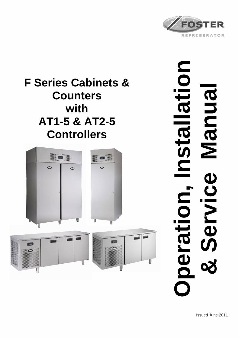
F Series Cabinets &
Counters with
AT1-5 & AT2-5 Controllers
Op
era
tio
n,
Ins
tall
ati
on
& S
erv
ice
M
an
ua
l
Issued June 2011
1
Contents
Manual Information & Health & Safety Notes 1
Environmental Management Policy 2
Disposal Requirements & Cabinet Description 2
Installation Instructions 3
Controller Information 4
Operation Instructions 5
Alarm & Warnings 6
Cleaning Instructions & Parameter setting & Adjustment 7
Parameters 8 to 10
Technical Data & Probe Details 11
Parts List – Cabinets & Counters 12 to 14
Parts Diagrams - Cabinet & Counter 15 to 16
Instructions of Reversing Door Hanging 17 to 20
Wiring Diagrams 21 to 25
Troubleshooting & Notes 26 to 28
Manual Information
The products and all information in this manual are subject to change without prior notice. We assume by the information given that the person(s) working on these refrigeration units are fully trained and skilled in all aspects of their workings. Also that they will use the appropriate safety equipment and take or meet
precautions where required. The service manual does not cover information on every variation of this unit; neither does it cover the installation
or every possible operating or maintenance instruction for the units.
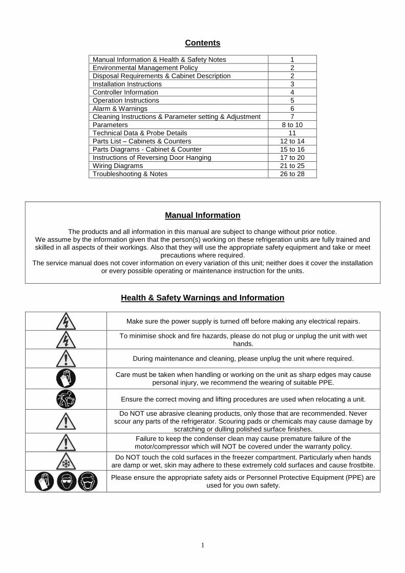
Health & Safety Warnings and Information
Make sure the power supply is turned off before making any electrical repairs.
To minimise shock and fire hazards, please do not plug or unplug the unit with wet hands.
During maintenance and cleaning, please unplug the unit where required.
Care must be taken when handling or working on the unit as sharp edges may cause personal injury, we recommend the wearing of suitable PPE.
Ensure the correct moving and lifting procedures are used when relocating a unit.
Do NOT use abrasive cleaning products, only those that are recommended. Never scour any parts of the refrigerator. Scouring pads or chemicals may cause damage by
scratching or dulling polished surface finishes.
Failure to keep the condenser clean may cause premature failure of the motor/compressor which will NOT be covered under the warranty policy.
Do NOT touch the cold surfaces in the freezer compartment. Particularly when hands are damp or wet, skin may adhere to these extremely cold surfaces and cause frostbite.
Please ensure the appropriate safety aids or Personnel Protective Equipment (PPE) are used for you own safety.
2
Environmental Management Policy for Service Manuals and Duets.
Product Support and Installation Contractors
Foster Refrigerator recognises that its activities, products and services can have an adverse impact upon the environment. The organisation is committed to implementing systems and controls to manage, reduce and eliminate its adverse environmental impacts wherever possible, and has formulated an Environmental Policy outlining our core aims. A copy of the Environmental Policy is available to all contractors and suppliers via our website. The organisation is committed to working with suppliers and contractors where their activities have the potential to impact upon the environment. To achieve the aims stated in the Environmental Policy we require that all suppliers and contractors operate in compliance with the law and are committed to best practice in environmental management.
Disposal Requirements If not disposed of properly all refrigerators have components that can be harmful to the environment. All old
refrigerators must be disposed of by appropriately registered and licensed waste contractors, and in accordance with national laws and regulations.
IMPORTANT To the Installer: Installation of these units should be carried out by a competent person and the appropriate codes
of practice adhered to, thus ensuring safe installation. Do not discard this document as it contains important guidelines on Operation, Loading, Cleaning and Maintenance
and should be kept for reference.
F Series Cabinet & Counter Descriptions The F range consists of a choice of capacities and temperature ranges in the Gastronorm format, accommodating GN2/1 (650mm x 530mm) or GN1/1 (530mm x 325mm) shelves or trays. The cabinets are manufactured as a one piece foam shell with easy clean stainless steel exterior The cabinets conform to current legislation and exceed the Montreal protocol using zero ODP refrigerants and insulation. There are 2 temperature options rated to Climate Class 5 operation (40
oC). Temperature is controlled by a
microprocessor control with digital temperature display. The display is clear and easy to read with a wipe clean finish. The refrigeration system is integral with an air-cooled condensing unit with the refrigerant distribution into the evaporator controlled by capillary tube. Remote systems are available as an option with the refrigerant distribution into the evaporator controlled by an expansion valve. The cooled air is circulated through the evaporator, via the fan into the storage area. The evaporator coil is coated with a special cataphoresis treatment to ensure longevity and corrosion resistance. A wide magnetic gasket ensures a positive door seal.
3
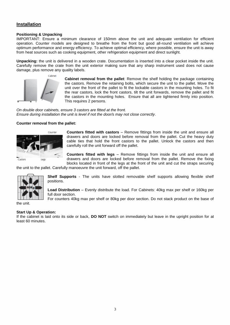
Installation Positioning & Unpacking IMPORTANT: Ensure a minimum clearance of 150mm above the unit and adequate ventilation for efficient operation. Counter models are designed to breathe from the front but good all-round ventilation will achieve optimum performance and energy efficiency. To achieve optimal efficiency, where possible, ensure the unit is away from heat sources such as cooking equipment, other refrigeration equipment and direct sunlight. Unpacking: the unit is delivered in a wooden crate. Documentation is inserted into a clear pocket inside the unit. Carefully remove the crate from the unit exterior making sure that any sharp instrument used does not cause damage, plus remove any quality labels.
Cabinet removal from the pallet: Remove the shelf holding the package containing the castors. Remove the retaining bolts, which secure the unit to the pallet. Move the unit over the front of the pallet to fit the lockable castors in the mounting holes. To fit the rear castors, lock the front castors, tilt the unit forwards, remove the pallet and fit the castors in the mounting holes. Ensure that all are tightened firmly into position. This requires 2 persons.
On double door cabinets, ensure 3 castors are fitted at the front. Ensure during installation the unit is level if not the door/s may not close correctly. Counter removal from the pallet:
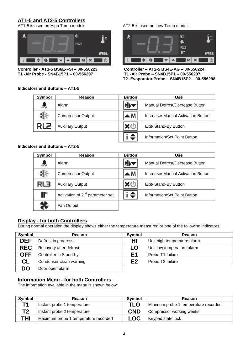
Counters fitted with castors – Remove fittings from inside the unit and ensure all drawers and doors are locked before removal from the pallet. Cut the heavy duty cable ties that hold the front castors to the pallet. Unlock the castors and then carefully roll the unit forward off the pallet. Counters fitted with legs – Remove fittings from inside the unit and ensure all drawers and doors are locked before removal from the pallet. Remove the fixing blocks located in front of the legs at the front of the unit and cut the straps securing
the unit to the pallet. Carefully manoeuvre the unit forward, off the pallet. Shelf Supports - The units have slotted removable shelf supports allowing flexible shelf positions. Load Distribution – Evenly distribute the load. For Cabinets: 40kg max per shelf or 160kg per full door section. For counters 40kg max per shelf or 80kg per door section. Do not stack product on the base of
the unit. Start Up & Operation: If the cabinet is laid onto its side or back, DO NOT switch on immediately but leave in the upright position for at least 60 minutes.
4
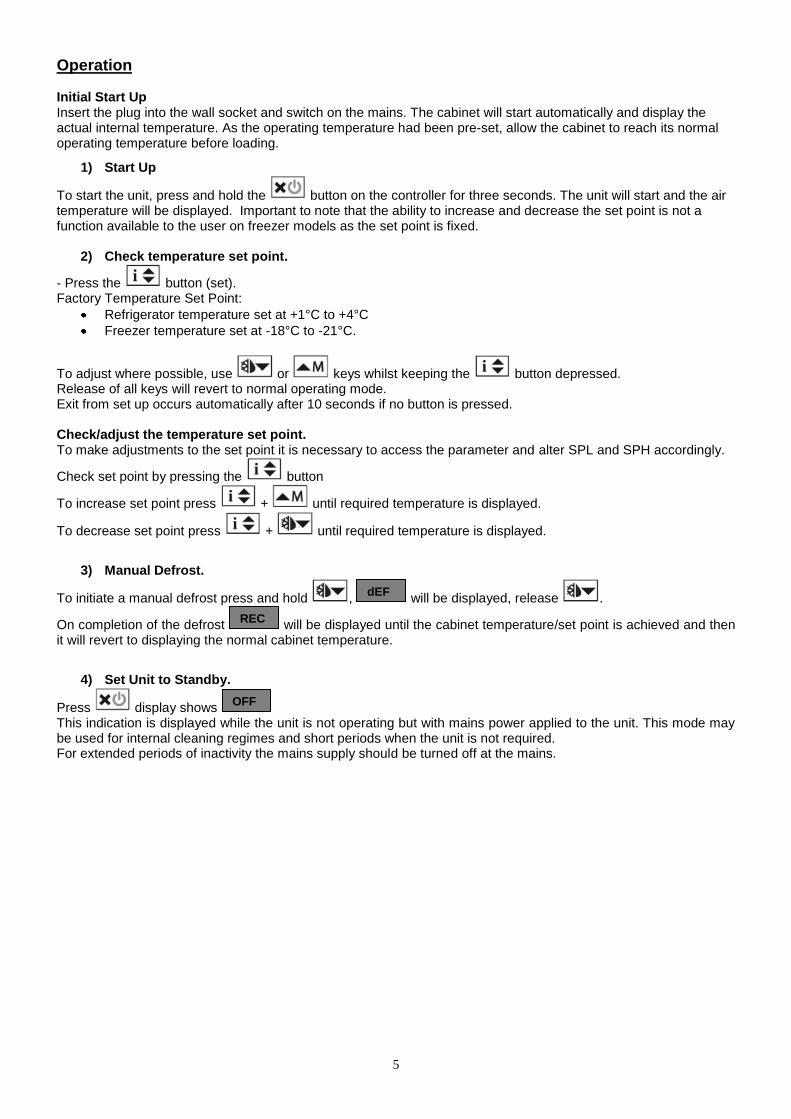
AT1-5 and AT2-5 Controllers AT1-5 is used on High Temp models AT2-5 is used on Low Temp models
Controller - AT1-5 BS6E-FSI – 00-556223 Controller – AT2-5 BS4E-AG – 00-556224 T1 -Air Probe - SN4B15P1 – 00-556297 T1 -Air Probe – SN4B15P1 – 00-556297
T2 -Evaporator Probe – SN4B15P2 – 00-556298
Indicators and Buttons – AT1-5
Indicators and Buttons – AT2-5
Display - for both Controllers During normal operation the display shows either the temperature measured or one of the following indicators:
Information Menu - for both Controllers The information available in the menu is shown below:
Symbol Reason Button Use
Alarm
Manual Defrost/Decrease Button
Compressor Output
Increase/ Manual Activation Button
Auxiliary Output
Exit/ Stand-By Button
Information/Set Point Button
Symbol Reason Button Use
Alarm
Manual Defrost/Decrease Button
Compressor Output
Increase/ Manual Activation Button
Auxiliary Output
Exit/ Stand-By Button
Activation of 2
nd parameter set
Information/Set Point Button
Fan Output
Symbol Reason Symbol Reason
DEF Defrost in progress HI Unit high temperature alarm
REC Recovery after defrost LO Unit low temperature alarm
OFF Controller in Stand-by E1 Probe T1 failure
CL Condenser clean warning E2 Probe T2 failure
DO Door open alarm
Symbol Reason Symbol Reason
T1 Instant probe 1 temperature TLO Minimum probe 1 temperature recorded
T2 Instant probe 2 temperature CND Compressor working weeks
THI Maximum probe 1 temperature recorded LOC Keypad state lock
5
Operation Initial Start Up Insert the plug into the wall socket and switch on the mains. The cabinet will start automatically and display the actual internal temperature. As the operating temperature had been pre-set, allow the cabinet to reach its normal operating temperature before loading.
1) Start Up
To start the unit, press and hold the button on the controller for three seconds. The unit will start and the air temperature will be displayed. Important to note that the ability to increase and decrease the set point is not a function available to the user on freezer models as the set point is fixed.
2) Check temperature set point.
- Press the button (set). Factory Temperature Set Point:
Refrigerator temperature set at +1°C to +4°C
Freezer temperature set at -18°C to -21°C.
To adjust where possible, use or keys whilst keeping the button depressed. Release of all keys will revert to normal operating mode. Exit from set up occurs automatically after 10 seconds if no button is pressed. Check/adjust the temperature set point. To make adjustments to the set point it is necessary to access the parameter and alter SPL and SPH accordingly.
Check set point by pressing the button
To increase set point press + until required temperature is displayed.
To decrease set point press + until required temperature is displayed.
3) Manual Defrost.
To initiate a manual defrost press and hold , will be displayed, release .
On completion of the defrost will be displayed until the cabinet temperature/set point is achieved and then it will revert to displaying the normal cabinet temperature.
4) Set Unit to Standby.
Press display shows This indication is displayed while the unit is not operating but with mains power applied to the unit. This mode may be used for internal cleaning regimes and short periods when the unit is not required. For extended periods of inactivity the mains supply should be turned off at the mains.
OFF
REC
dEF
6
Alarm and Warnings
High temperature alarm
Will be displayed. The alarm will sound but can be silenced by pressing any of the buttons, however it will return after the pre-set designated period. The unit returning to normal operating temperature will automatically cancel the alarm. Possible Causes: Evaporator fan not working. Restricted airflow through air duct. Evaporator iced up. Compressor not working.
Low temperature alarm.
Will be displayed. The alarm will sound but can be silenced by pressing any of the buttons and the unit will continue to operate, however it will return after the pre-set designated period. The unit returning to normal operating temperature will automatically cancel the alarm. Possible Causes: Controller faulty (not switching compressor off). Compressor secondary relay will not de-energise (low temperature models). Door Open Alarm. („DS‟ set to „YES‟. Only applies to cabinets fitted with door switches.)
Will be displayed.
The alarm will sound but can be silenced by pressing . The display will continue to display the alarm message until cancelled by shutting the door. If the alarm cannot be cancelled by doing this call your Foster Authorised Service Company. Possible Causes: Faulty door switch. Door left open for more than 5minutes. Air Temperature Probe Failure.
Will be displayed. The alarm will sound but can be silenced by pressing any button. There is no further action that can be taken by the user in this instance. During this period the unit will continue to operate but have a reduced performance. Action: Replace Probe.
Evaporator Temperature Probe Failure. (Automatic Defrost Cabinets Only)
Will be displayed. The alarm will sound but can be silenced by pressing any button. There is no further action that can be taken by the user in this instance. During this period the unit will continue to operate satisfactorily, but this failure will have an effect on the defrost and therefore efficiency if allowed to continue. Action: Replace Probe.
Information Menu
Pressing and releasing activates the information menu. From this menu you can display the temperature relating to T1 (air probe), T2 (evaporator probe, if fitted) and T3 (condenser probe, if fitted). The maximum temperature (THI) and the minimum temperature (TLO) the cabinet has achieved since it was last re-set. The total operating time of the condenser (CND), since it was last cleaned, and the keyboard status (LOC).
The information to be displayed can be selected sequentially by pressing repeatedly or scrolling
through the menu using the or buttons.
Once selected press to display the value
Exit from the info menu by pressing or is automatic after 6 seconds if no buttons are pressed. To reset the temperature settings recorded in THI and TLO and the hours counted in CND, access the info menu
press to display the value plus simultaneously for resetting to be completed.
To check the LOC status scroll through to LOC, press to display status – YES to lock keys. – NO to leave keys accessible. NOTE: with the keys locked it is not possible to turn the unit off or ON or to check the set point
E2
E1
DO
LO
HI
7
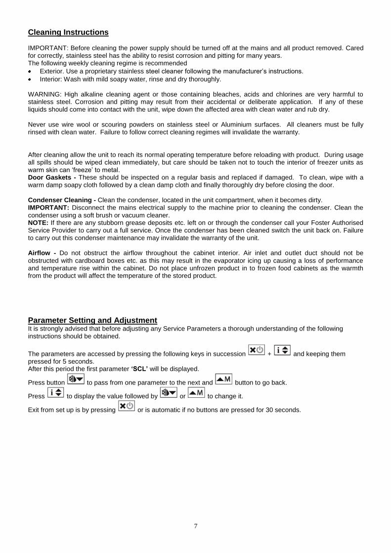
Cleaning Instructions
IMPORTANT: Before cleaning the power supply should be turned off at the mains and all product removed. Cared for correctly, stainless steel has the ability to resist corrosion and pitting for many years. The following weekly cleaning regime is recommended
Exterior. Use a proprietary stainless steel cleaner following the manufacturer‟s instructions.
Interior: Wash with mild soapy water, rinse and dry thoroughly. WARNING: High alkaline cleaning agent or those containing bleaches, acids and chlorines are very harmful to stainless steel. Corrosion and pitting may result from their accidental or deliberate application. If any of these liquids should come into contact with the unit, wipe down the affected area with clean water and rub dry. Never use wire wool or scouring powders on stainless steel or Aluminium surfaces. All cleaners must be fully rinsed with clean water. Failure to follow correct cleaning regimes will invalidate the warranty. After cleaning allow the unit to reach its normal operating temperature before reloading with product. During usage all spills should be wiped clean immediately, but care should be taken not to touch the interior of freezer units as warm skin can „freeze‟ to metal. Door Gaskets - These should be inspected on a regular basis and replaced if damaged. To clean, wipe with a warm damp soapy cloth followed by a clean damp cloth and finally thoroughly dry before closing the door. Condenser Cleaning - Clean the condenser, located in the unit compartment, when it becomes dirty. IMPORTANT: Disconnect the mains electrical supply to the machine prior to cleaning the condenser. Clean the condenser using a soft brush or vacuum cleaner. NOTE: If there are any stubborn grease deposits etc. left on or through the condenser call your Foster Authorised Service Provider to carry out a full service. Once the condenser has been cleaned switch the unit back on. Failure to carry out this condenser maintenance may invalidate the warranty of the unit. Airflow - Do not obstruct the airflow throughout the cabinet interior. Air inlet and outlet duct should not be obstructed with cardboard boxes etc. as this may result in the evaporator icing up causing a loss of performance and temperature rise within the cabinet. Do not place unfrozen product in to frozen food cabinets as the warmth from the product will affect the temperature of the stored product.
Parameter Setting and Adjustment It is strongly advised that before adjusting any Service Parameters a thorough understanding of the following instructions should be obtained.
The parameters are accessed by pressing the following keys in succession + and keeping them pressed for 5 seconds. After this period the first parameter ‘SCL’ will be displayed.
Press button to pass from one parameter to the next and button to go back.
Press to display the value followed by or to change it.
Exit from set up is by pressing or is automatic if no buttons are pressed for 30 seconds.
8
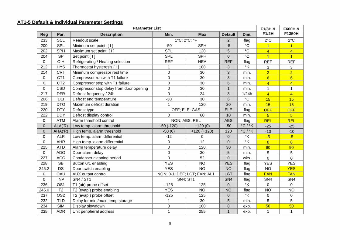
AT1-5 Default & Individual Parameter Settings Parameter List F1/3H &
F1/2H F600H & F1350H Reg Par. Description Min. Max Default Dim.
233 SCL Readout scale 1°C; 2°C; °F 2 flag 2°C 2°C
200 SPL Minimum set point [ I ] -50 SPH -5 °C 1 1
202 SPH Maximum set point [ I ] SPL 120 5 °C 4 4
204 SP Set point [ I ] SPL SPH 0 °C 1 1
0 C-H Refrigerating / Heating selection REF HEA REF flag REF REF
212 HYS Thermostat hysteresis [ I ] 1 100 3 °K 3 3
214 CRT Minimum compressor rest time 0 30 3 min. 2 2
0 CT1 Compressor run with T1 failure 0 30 3 min. 6 6
0 CT2 Compressor stop with T1 failure 0 30 6 min. 4 4
0 CSD Compressor stop delay from door opening 0 30 1 min. 1 1
217 DFR Defrost frequency / 24h 0 24 3 1/24h 4 4
206 DLI Defrost end temperature -30 30 6 °C 15 15
219 DTO Maximum defrost duration 1 120 20 min. 15 15
220 DTY Defrost type OFF; ELE; GAS ELE flag OFF OFF
222 DDY Defrost display control 0 60 10 min. 5 5
0 ATM Alarm threshold control NON; ABS; REL ABS flag REL REL
0 ALA('R) Low temp. alarm threshold -50 (-120) +120 (0) -50 °C / °K -25 -25
0 AHA('R) High temp. alarm threshold -50 (0) +120 (+120) 120 °C / °K -10 -10
0 ALR Low temp. alarm differential -12 0 0 °K -5 -5
0 AHR High temp. alarm differential 0 12 0 °K 8 8
225 ATD Alarm temperature delay 0 120 30 min. 90 90
0 ADO Door alarm delay 0 30 5 min. 5 5
227 ACC Condenser cleaning period 0 52 0 wks. 0 0
228 SB Button 0/1 enabling YES NO YES flag YES YES
245.2 DS Door switch enabling YES NO NO flag NO YES
0 OAU AUX output control NON; 0-1; DEF; LGT; FAN; AL1 LGT flag FAN FAN
0 INP SN4 / ST1 SN4; ST1 SN4 flag SN4 SN4
236 OS1 T1 (air) probe offset -125 125 0 °K 0 0
245.0 T2 T2 (evap.) probe enabling YES NO NO flag NO NO
237 OS2 T2 (evap.) probe offset -125 125 0 °K 0 0
232 TLD Delay for min./max. temp storage 1 30 5 min. 5 5
234 SIM Display slowdown 0 100 0 exp. 50 50
235 ADR Unit peripheral address 1 255 1 exp. 1 1
9
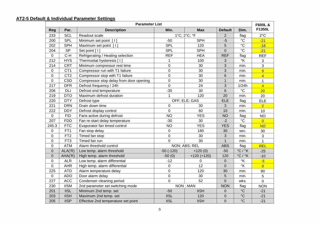
AT2-5 Default & Individual Parameter Settings Parameter List F600L &
F1350L Reg Par. Description Min. Max Default Dim.
233 SCL Readout scale 1°C; 2°C; °F 2 flag 2°C
200 SPL Minimum set point [ I ] -50 SPH -5 °C -21
202 SPH Maximum set point [ I ] SPL 120 5 °C -18
204 SP Set point [ I ] SPL SPH 0 °C -21
0 C-H Refrigerating / Heating selection REF HEA REF flag REF
212 HYS Thermostat hysteresis [ I ] 1 100 3 °K 3
214 CRT Minimum compressor rest time 0 30 3 min. 3
0 CT1 Compressor run with T1 failure 0 30 3 min. 6
0 CT2 Compressor stop with T1 failure 0 30 6 min. 4
0 CSD Compressor stop delay from door opening 0 30 1 min. 1
217 DFR Defrost frequency / 24h 0 24 3 1/24h 4
206 DLI Defrost end temperature -30 30 6 °C 20
219 DTO Maximum defrost duration 1 120 20 min. 20
220 DTY Defrost type OFF; ELE; GAS ELE flag ELE
221 DRN Drain down time 0 30 3 min. 2
222 DDY Defrost display control 0 60 10 min. 10
0 FID Fans active during defrost NO YES NO flag NO
207 FDD Fan re-start delay temperature -30 30 -2 °C 0
245.3 FTC Evaporator fan timed control NO YES YES flag NO
0 FT1 Fan stop delay 0 180 30 sec. 30
0 FT2 Timed fan stop 0 30 3 min. 3
0 FT3 Timed fan run 0 30 1 min. 1
0 ATM Alarm threshold control NON; ABS; REL ABS flag REL
0 ALA('R) Low temp. alarm threshold -50 (-120) +120 (0) -50 °C / °K -25
0 AHA('R) High temp. alarm threshold -50 (0) +120 (+120) 120 °C / °K -10
0 ALR Low temp. alarm differential -12 0 0 °K -5
0 AHR High temp. alarm differential 0 12 0 °K 8
225 ATD Alarm temperature delay 0 120 30 min. 90
0 ADO Door alarm delay 0 30 5 min. 5
227 ACC Condenser cleaning period 0 52 0 wks. 0
230 IISM 2nd parameter set switching mode NON ; MAN NON flag NON
201 IISL Minimum 2nd temp. set -50 IISH 0 °C -21
203 IISH Maximum 2nd temp. set IISL 120 0 °C -21
205 IISP Effective 2nd temperature set point IISL IISH 0 °C -21
10
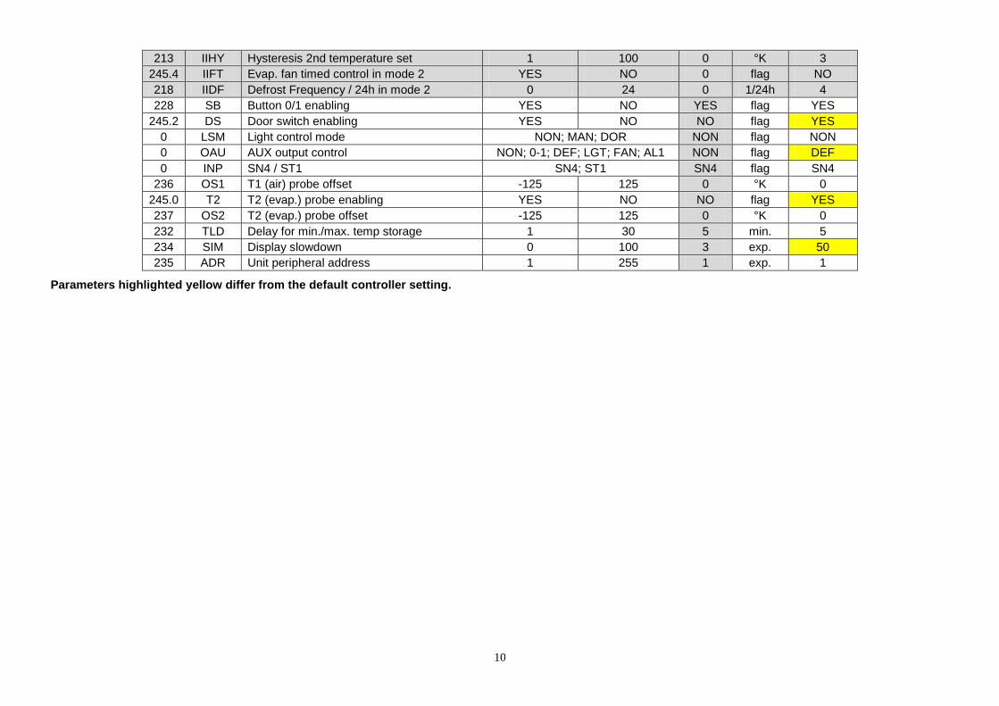
213 IIHY Hysteresis 2nd temperature set 1 100 0 °K 3
245.4 IIFT Evap. fan timed control in mode 2 YES NO 0 flag NO
218 IIDF Defrost Frequency / 24h in mode 2 0 24 0 1/24h 4
228 SB Button 0/1 enabling YES NO YES flag YES
245.2 DS Door switch enabling YES NO NO flag YES
0 LSM Light control mode NON; MAN; DOR NON flag NON
0 OAU AUX output control NON; 0-1; DEF; LGT; FAN; AL1 NON flag DEF
0 INP SN4 / ST1 SN4; ST1 SN4 flag SN4
236 OS1 T1 (air) probe offset -125 125 0 °K 0
245.0 T2 T2 (evap.) probe enabling YES NO NO flag YES
237 OS2 T2 (evap.) probe offset -125 125 0 °K 0
232 TLD Delay for min./max. temp storage 1 30 5 min. 5
234 SIM Display slowdown 0 100 3 exp. 50
235 ADR Unit peripheral address 1 255 1 exp. 1
Parameters highlighted yellow differ from the default controller setting.
11
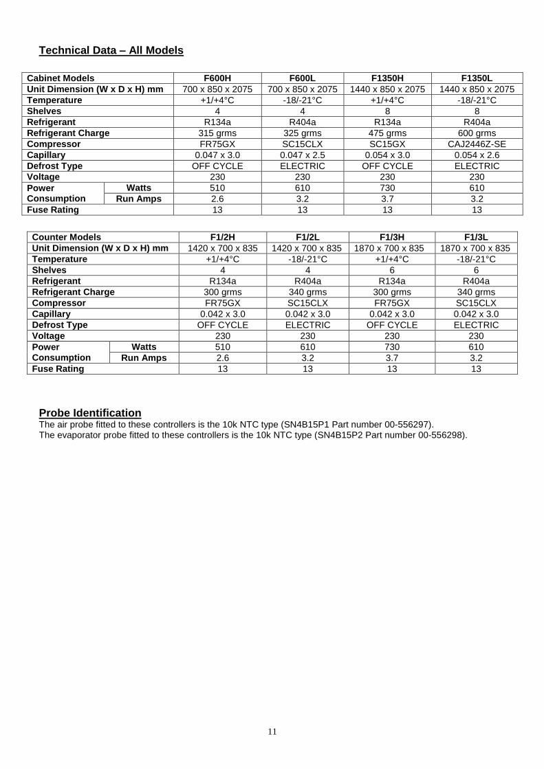
Technical Data – All Models
Cabinet Models F600H F600L F1350H F1350L
Unit Dimension (W x D x H) mm 700 x 850 x 2075 700 x 850 x 2075 1440 x 850 x 2075 1440 x 850 x 2075
Temperature +1/+4°C -18/-21°C +1/+4°C -18/-21°C
Shelves 4 4 8 8
Refrigerant R134a R404a R134a R404a
Refrigerant Charge 315 grms 325 grms 475 grms 600 grms
Compressor FR75GX SC15CLX SC15GX CAJ2446Z-SE
Capillary 0.047 x 3.0 0.047 x 2.5 0.054 x 3.0 0.054 x 2.6
Defrost Type OFF CYCLE ELECTRIC OFF CYCLE ELECTRIC
Voltage 230 230 230 230
Power Consumption
Watts 510 610 730 610
Run Amps 2.6 3.2 3.7 3.2
Fuse Rating 13 13 13 13
Counter Models F1/2H F1/2L F1/3H F1/3L
Unit Dimension (W x D x H) mm 1420 x 700 x 835 1420 x 700 x 835 1870 x 700 x 835 1870 x 700 x 835
Temperature +1/+4°C -18/-21°C +1/+4°C -18/-21°C
Shelves 4 4 6 6
Refrigerant R134a R404a R134a R404a
Refrigerant Charge 300 grms 340 grms 300 grms 340 grms
Compressor FR75GX SC15CLX FR75GX SC15CLX
Capillary 0.042 x 3.0 0.042 x 3.0 0.042 x 3.0 0.042 x 3.0
Defrost Type OFF CYCLE ELECTRIC OFF CYCLE ELECTRIC
Voltage 230 230 230 230
Power Consumption
Watts 510 610 730 610
Run Amps 2.6 3.2 3.7 3.2
Fuse Rating 13 13 13 13
Probe Identification
The air probe fitted to these controllers is the 10k NTC type (SN4B15P1 Part number 00-556297).
The evaporator probe fitted to these controllers is the 10k NTC type (SN4B15P2 Part number 00-556298).
12
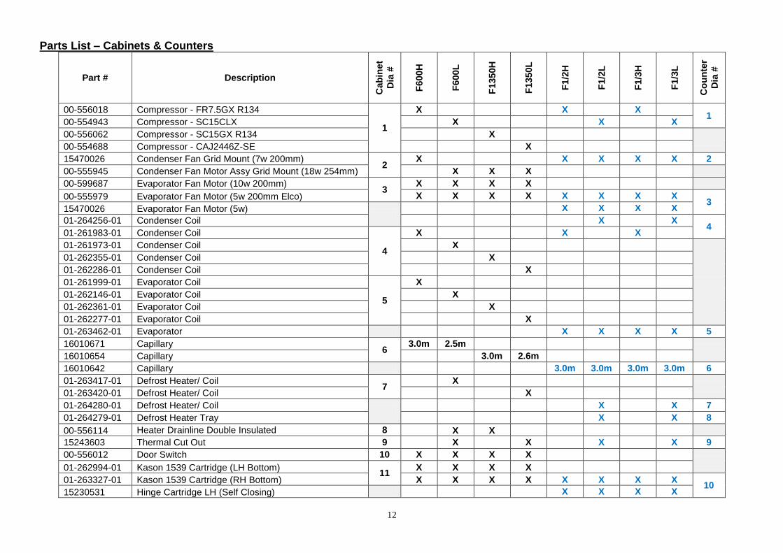
Parts List – Cabinets & Counters
Part # Description
Cab
inet
Dia
#
F600H
F600
L
F1350H
F1350L
F1/2
H
F1/2
L
F1/3
H
F1/3
L
Co
un
ter
Dia
#
00-556018 Compressor - FR7.5GX R134
1
X X
X 1
00-554943 Compressor - SC15CLX X X X
00-556062 Compressor - SC15GX R134 X
00-554688 Compressor - CAJ2446Z-SE X
15470026 Condenser Fan Grid Mount (7w 200mm) 2
X X X X X 2
00-555945 Condenser Fan Motor Assy Grid Mount (18w 254mm) X X X
00-599687 Evaporator Fan Motor (10w 200mm) 3
X X X X
00-555979 Evaporator Fan Motor (5w 200mm Elco) X X X X X X X X 3
15470026 Evaporator Fan Motor (5w)
X X X X
01-264256-01 Condenser Coil X X 4
01-261983-01 Condenser Coil
4
X X X
01-261973-01 Condenser Coil X
01-262355-01 Condenser Coil X
01-262286-01 Condenser Coil X
01-261999-01 Evaporator Coil
5
X
01-262146-01 Evaporator Coil X
01-262361-01 Evaporator Coil X
01-262277-01 Evaporator Coil X
01-263462-01 Evaporator X X X X 5
16010671 Capillary 6
3.0m 2.5m
16010654 Capillary 3.0m 2.6m
16010642 Capillary 3.0m 3.0m 3.0m 3.0m 6
01-263417-01 Defrost Heater/ Coil 7
X
01-263420-01 Defrost Heater/ Coil X
01-264280-01 Defrost Heater/ Coil
X X 7
01-264279-01 Defrost Heater Tray X X 8
00-556114 Heater Drainline Double Insulated 8 X X
15243603 Thermal Cut Out 9 X X X X 9
00-556012 Door Switch 10 X X X X
01-262994-01 Kason 1539 Cartridge (LH Bottom) 11
X X X X
01-263327-01 Kason 1539 Cartridge (RH Bottom) X X X X X X X X 10
15230531 Hinge Cartridge LH (Self Closing) X X X X
13
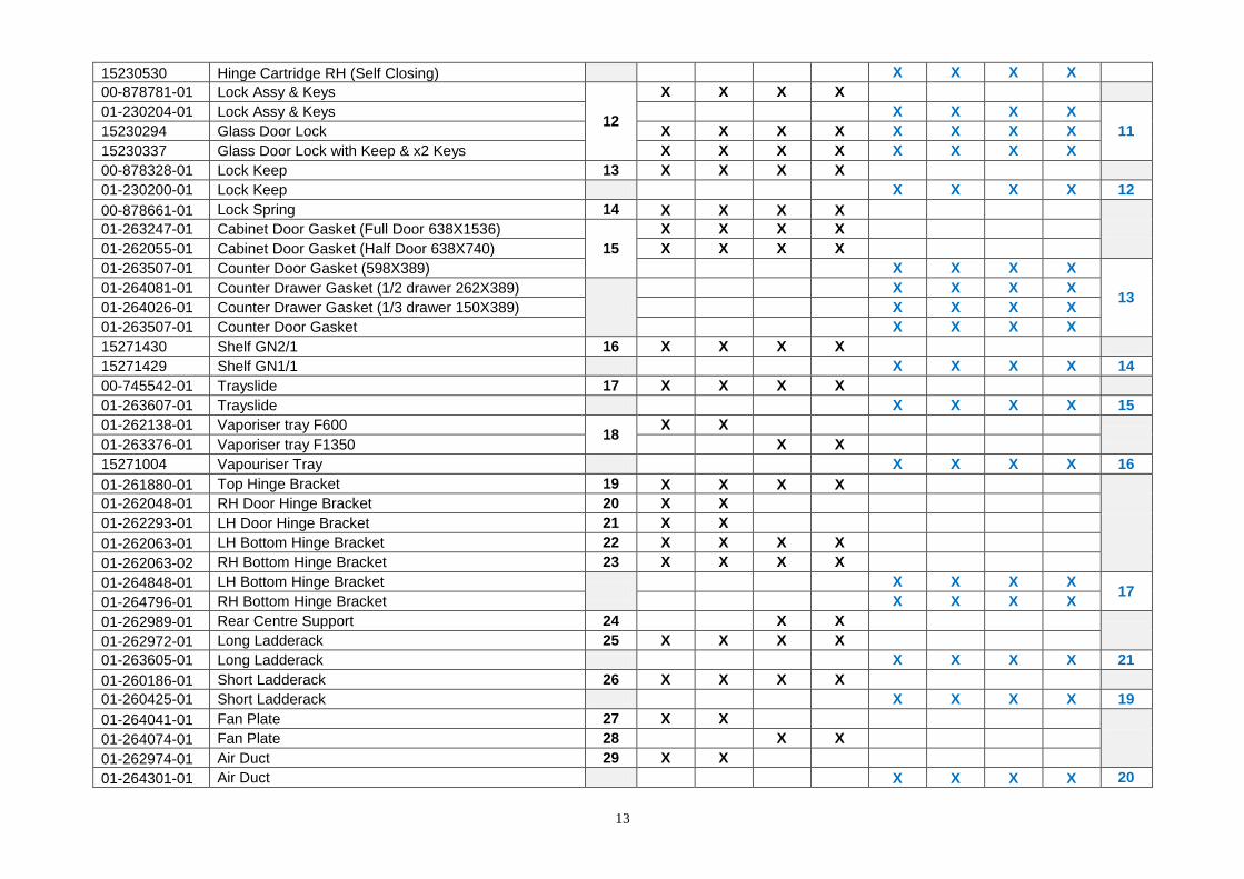
15230530 Hinge Cartridge RH (Self Closing) X X X X
00-878781-01 Lock Assy & Keys
12
X X X X
01-230204-01 Lock Assy & Keys X X X X
11 15230294 Glass Door Lock X X X X X X X X
15230337 Glass Door Lock with Keep & x2 Keys X X X X X X X X
00-878328-01 Lock Keep 13 X X X X
01-230200-01 Lock Keep X X X X 12
00-878661-01 Lock Spring 14 X X X X
01-263247-01 Cabinet Door Gasket (Full Door 638X1536)
15
X X X X
01-262055-01 Cabinet Door Gasket (Half Door 638X740) X X X X
01-263507-01 Counter Door Gasket (598X389) X X X X
13 01-264081-01 Counter Drawer Gasket (1/2 drawer 262X389)
X X X X
01-264026-01 Counter Drawer Gasket (1/3 drawer 150X389) X X X X
01-263507-01 Counter Door Gasket X X X X
15271430 Shelf GN2/1 16 X X X X
15271429 Shelf GN1/1 X X X X 14
00-745542-01 Trayslide 17 X X X X
01-263607-01 Trayslide X X X X 15
01-262138-01 Vaporiser tray F600 18
X X
01-263376-01 Vaporiser tray F1350 X X
15271004 Vapouriser Tray X X X X 16
01-261880-01 Top Hinge Bracket 19 X X X X
01-262048-01 RH Door Hinge Bracket 20 X X
01-262293-01 LH Door Hinge Bracket 21 X X
01-262063-01 LH Bottom Hinge Bracket 22 X X X X
01-262063-02 RH Bottom Hinge Bracket 23 X X X X
01-264848-01 LH Bottom Hinge Bracket
X X X X 17
01-264796-01 RH Bottom Hinge Bracket X X X X
01-262989-01 Rear Centre Support 24 X X
01-262972-01 Long Ladderack 25 X X X X
01-263605-01 Long Ladderack X X X X 21
01-260186-01 Short Ladderack 26 X X X X
01-260425-01 Short Ladderack X X X X 19
01-264041-01 Fan Plate 27 X X
01-264074-01 Fan Plate 28 X X
01-262974-01 Air Duct 29 X X
01-264301-01 Air Duct X X X X 20
14
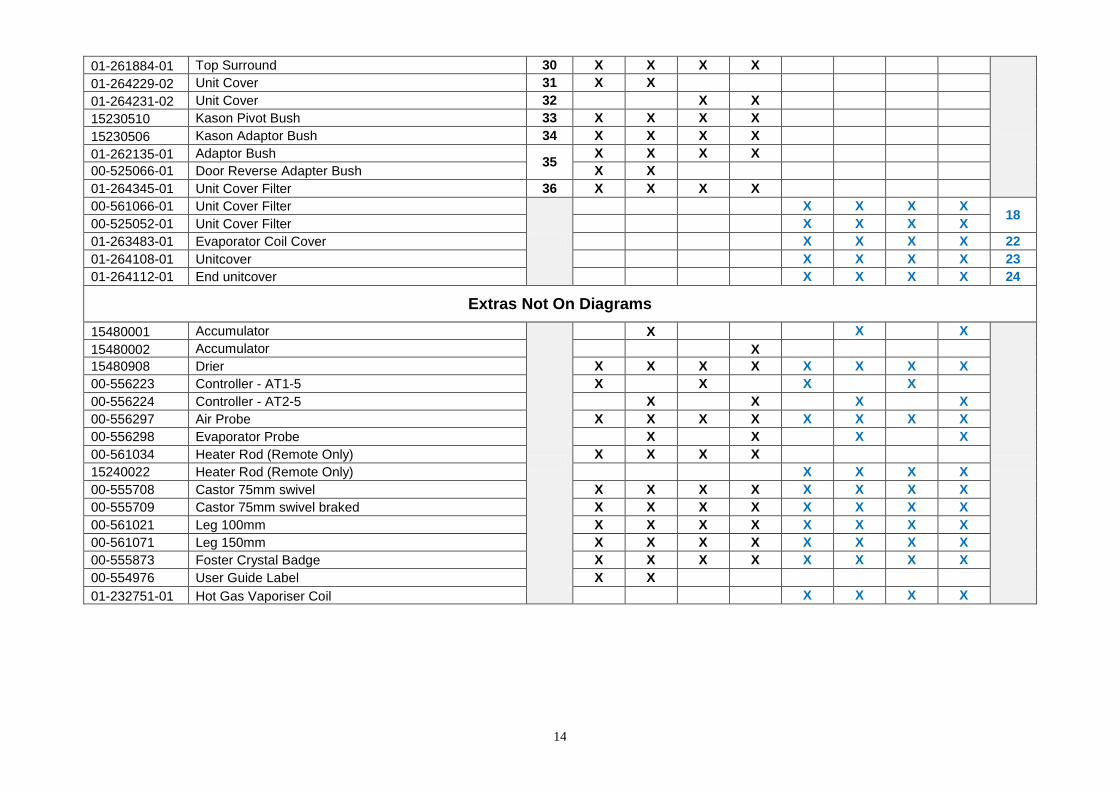
01-261884-01 Top Surround 30 X X X X
01-264229-02 Unit Cover 31 X X
01-264231-02 Unit Cover 32 X X
15230510 Kason Pivot Bush 33 X X X X
15230506 Kason Adaptor Bush 34 X X X X
01-262135-01 Adaptor Bush 35
X X X X
00-525066-01 Door Reverse Adapter Bush X X
01-264345-01 Unit Cover Filter 36 X X X X
00-561066-01 Unit Cover Filter
X X X X 18
00-525052-01 Unit Cover Filter X X X X
01-263483-01 Evaporator Coil Cover X X X X 22
01-264108-01 Unitcover X X X X 23
01-264112-01 End unitcover X X X X 24
Extras Not On Diagrams
15480001 Accumulator
X X X
15480002 Accumulator X
15480908 Drier X X X X X X X X
00-556223 Controller - AT1-5 X X X X
00-556224 Controller - AT2-5 X X X X
00-556297 Air Probe X X X X X X X X
00-556298 Evaporator Probe X X X X
00-561034 Heater Rod (Remote Only) X X X X
15240022 Heater Rod (Remote Only) X X X X
00-555708 Castor 75mm swivel X X X X X X X X
00-555709 Castor 75mm swivel braked X X X X X X X X
00-561021 Leg 100mm X X X X X X X X
00-561071 Leg 150mm X X X X X X X X
00-555873 Foster Crystal Badge X X X X X X X X
00-554976 User Guide Label X X
01-232751-01 Hot Gas Vaporiser Coil X X X X

15
Parts List Diagram - Cabinets
16
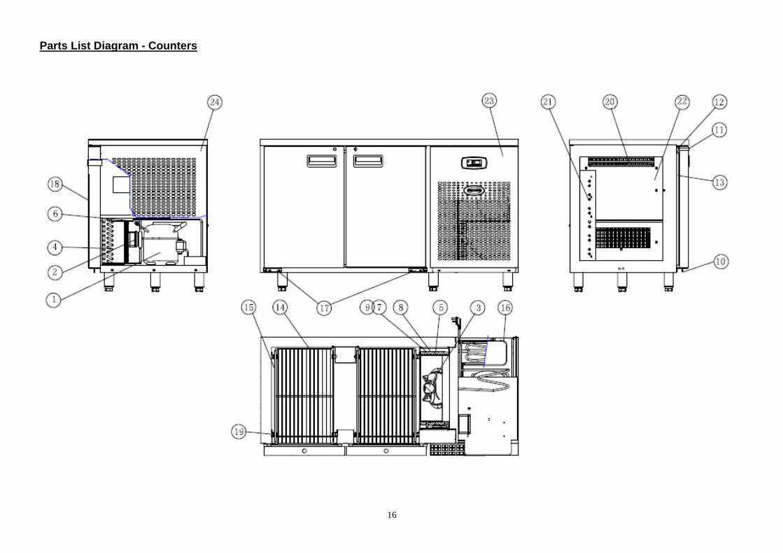
Parts List Diagram - Counters
17
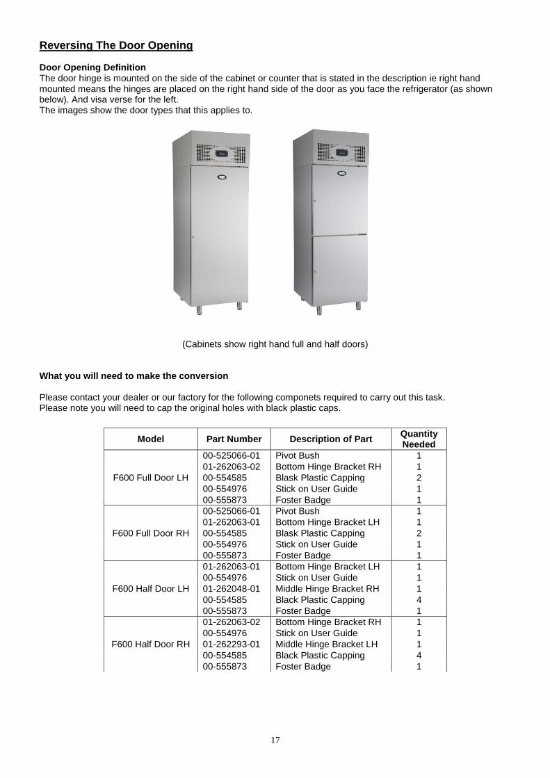
Reversing The Door Opening Door Opening Definition The door hinge is mounted on the side of the cabinet or counter that is stated in the description ie right hand mounted means the hinges are placed on the right hand side of the door as you face the refrigerator (as shown below). And visa verse for the left. The images show the door types that this applies to.
(Cabinets show right hand full and half doors) What you will need to make the conversion Please contact your dealer or our factory for the following componets required to carry out this task. Please note you will need to cap the original holes with black plastic caps.
Model Part Number Description of Part Quantity Needed
F600 Full Door LH
00-525066-01 Pivot Bush 1
01-262063-02 Bottom Hinge Bracket RH 1
00-554585 Blask Plastic Capping 2
00-554976 Stick on User Guide 1
00-555873 Foster Badge 1
F600 Full Door RH
00-525066-01 Pivot Bush 1
01-262063-01 Bottom Hinge Bracket LH 1
00-554585 Blask Plastic Capping 2
00-554976 Stick on User Guide 1
00-555873 Foster Badge 1
F600 Half Door LH
01-262063-01 Bottom Hinge Bracket LH 1
00-554976 Stick on User Guide 1
01-262048-01 Middle Hinge Bracket RH 1
00-554585 Black Plastic Capping 4
00-555873 Foster Badge 1
F600 Half Door RH
01-262063-02 Bottom Hinge Bracket RH 1
00-554976 Stick on User Guide 1
01-262293-01 Middle Hinge Bracket LH 1
00-554585 Black Plastic Capping 4
00-555873 Foster Badge 1
18
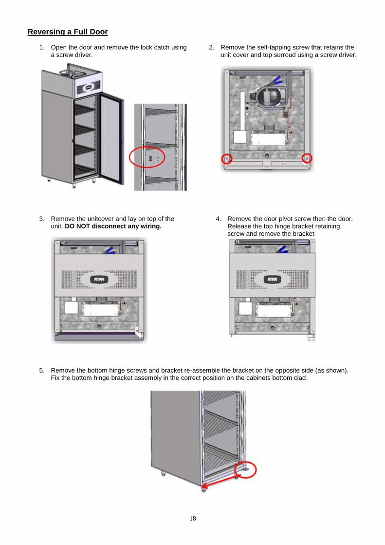
Reversing a Full Door
1. Open the door and remove the lock catch using a screw driver.
2. Remove the self-tapping screw that retains the unit cover and top surroud using a screw driver.
3. Remove the unitcover and lay on top of the unit. DO NOT disconnect any wiring.
4. Remove the door pivot screw then the door. Release the top hinge bracket retaining screw and remove the bracket
5. Remove the bottom hinge screws and bracket re-assemble the bracket on the opposite side (as shown). Fix the bottom hinge bracket assembly in the correct position on the cabinets bottom clad.
19
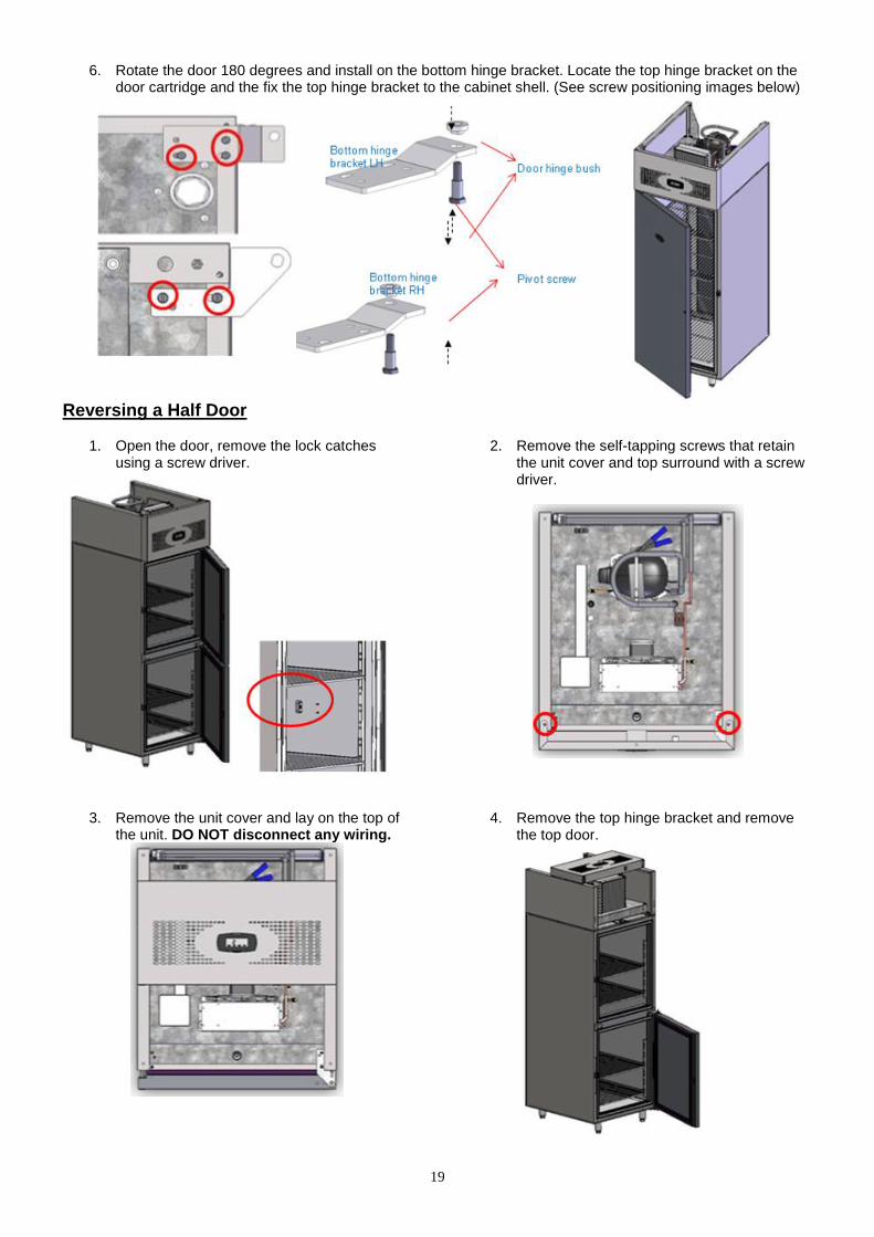
6. Rotate the door 180 degrees and install on the bottom hinge bracket. Locate the top hinge bracket on the door cartridge and the fix the top hinge bracket to the cabinet shell. (See screw positioning images below)
Reversing a Half Door
1. Open the door, remove the lock catches using a screw driver.
2. Remove the self-tapping screws that retain the unit cover and top surround with a screw driver.
3. Remove the unit cover and lay on the top of the unit. DO NOT disconnect any wiring.
4. Remove the top hinge bracket and remove the top door.
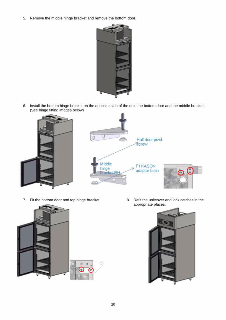
20
5. Remove the middle hinge bracket and remove the bottom door.
6. Install the bottom hinge bracket on the opposite side of the unit, the bottom door and the middle bracket. (See hinge fitting images below)
7. Fit the bottom door and top hinge bracket
8. Refit the unitcover and lock catches in the appropriate places.
21
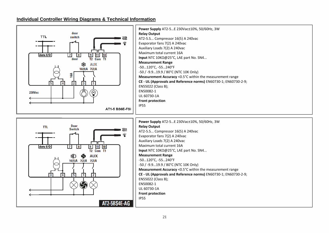
Individual Controller Wiring Diagrams & Technical Information
Power Supply AT2-5…E 230Vac±10%, 50/60Hz, 3W Relay Output AT2-5.S... Compressor 16(5) A 240vac Evaporator fans 7(2) A 240vac Auxiliary Loads 7(2) A 240vac Maximum total current 16A Input NTC 10KΩ@25°C, LAE part No. SN4... Measurement Range -50…120°C, -55…240°F -50 / -9.9…19.9 / 80°C (NTC 10K Only) Measurement Accuracy <0.5°C within the measurement range CE - UL (Approvals and Reference norms) EN60730-1; EN60730-2-9; EN55022 (Class B); EN50082-1 UL 60730-1A Front protection IP55
Power Supply AT2-5…E 230Vac±10%, 50/60Hz, 3W Relay Output AT2-5.S... Compressor 16(5) A 240vac Evaporator fans 7(2) A 240vac Auxiliary Loads 7(2) A 240vac Maximum total current 16A Input NTC 10KΩ@25°C, LAE part No. SN4... Measurement Range -50…120°C, -55…240°F -50 / -9.9…19.9 / 80°C (NTC 10K Only) Measurement Accuracy <0.5°C within the measurement range CE - UL (Approvals and Reference norms) EN60730-1; EN60730-2-9; EN55022 (Class B); EN50082-1 UL 60730-1A Front protection IP55
22
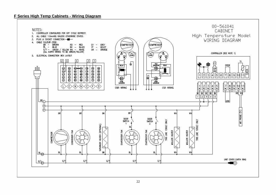
F Series High Temp Cabinets - Wiring Diagram
23
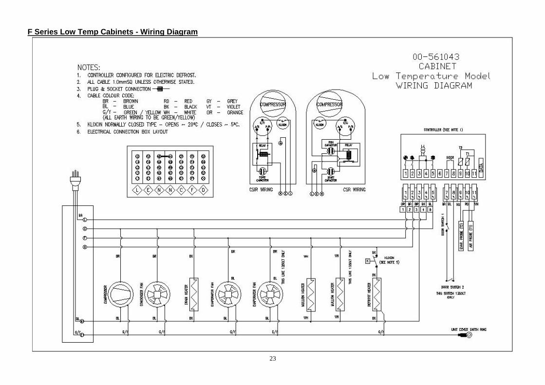
F Series Low Temp Cabinets - Wiring Diagram
24
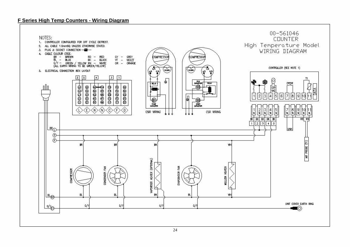
F Series High Temp Counters - Wiring Diagram

25
F Series Low Temp Counters - Wiring Diagram
26
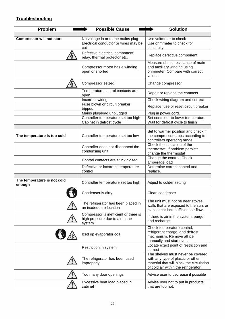
Troubleshooting
Problem Possible Cause Solution
Compressor will not start No voltage in or to the mains plug Use voltmeter to check
Electrical conductor or wires may be cut
Use ohmmeter to check for continuity
Defective electrical component: relay, thermal protector etc.
Replace defective component
Compressor motor has a winding open or shorted
Measure ohmic resistance of main and auxiliary winding using ohmmeter. Compare with correct values
Compressor seized. Change compressor
Temperature control contacts are open
Repair or replace the contacts
Incorrect wiring Check wiring diagram and correct
Fuse blown or circuit breaker tripped.
Replace fuse or reset circuit breaker
Mains plug/lead unplugged Plug in power cord.
Controller temperature set too high Set controller to lower temperature.
Cabinet in defrost cycle Wait for defrost cycle to finish
The temperature is too cold Controller temperature set too low Set to warmer position and check if the compressor stops according to controllers operating range.
Controller does not disconnect the condensing unit
Check the insulation of the thermostat. If problem persists, change the thermostat
Control contacts are stuck closed Change the control. Check amperage load
Defective or incorrect temperature control
Determine correct control and replace.
The temperature is not cold enough
Controller temperature set too high Adjust to colder setting
Condenser is dirty Clean condenser
The refrigerator has been placed in an inadequate location
The unit must not be near stoves, walls that are exposed to the sun, or places that lack sufficient air flow.
Compressor is inefficient or there is high pressure due to air in the system
If there is air in the system, purge and recharge
Iced up evaporator coil
Check temperature control, refrigerant charge, and defrost mechanism. Remove all ice manually and start over.
Restriction in system Locate exact point of restriction and correct
The refrigerator has been used improperly
The shelves must never be covered with any type of plastic or other material that will block the circulation of cold air within the refrigerator.
Too many door openings Advise user to decrease if possible
Excessive heat load placed in cabinet
Advise user not to put in products that are too hot.
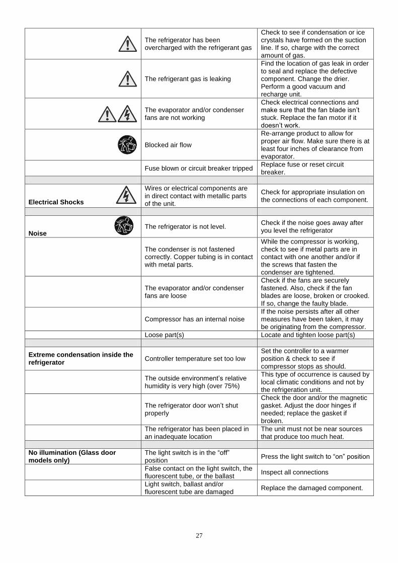
27
The refrigerator has been overcharged with the refrigerant gas
Check to see if condensation or ice crystals have formed on the suction line. If so, charge with the correct amount of gas.
The refrigerant gas is leaking
Find the location of gas leak in order to seal and replace the defective component. Change the drier. Perform a good vacuum and recharge unit.
The evaporator and/or condenser fans are not working
Check electrical connections and make sure that the fan blade isn‟t stuck. Replace the fan motor if it doesn‟t work.
Blocked air flow
Re-arrange product to allow for proper air flow. Make sure there is at least four inches of clearance from evaporator.
Fuse blown or circuit breaker tripped Replace fuse or reset circuit breaker.
Electrical Shocks
Wires or electrical components are in direct contact with metallic parts of the unit.
Check for appropriate insulation on the connections of each component.
Noise The refrigerator is not level.
Check if the noise goes away after you level the refrigerator
The condenser is not fastened correctly. Copper tubing is in contact with metal parts.
While the compressor is working, check to see if metal parts are in contact with one another and/or if the screws that fasten the condenser are tightened.
The evaporator and/or condenser fans are loose
Check if the fans are securely fastened. Also, check if the fan blades are loose, broken or crooked. If so, change the faulty blade.
Compressor has an internal noise If the noise persists after all other measures have been taken, it may be originating from the compressor.
Loose part(s) Locate and tighten loose part(s)
Extreme condensation inside the refrigerator
Controller temperature set too low Set the controller to a warmer position & check to see if compressor stops as should.
The outside environment‟s relative humidity is very high (over 75%)
This type of occurrence is caused by local climatic conditions and not by the refrigeration unit.
The refrigerator door won‟t shut properly
Check the door and/or the magnetic gasket. Adjust the door hinges if needed; replace the gasket if broken.
The refrigerator has been placed in an inadequate location
The unit must not be near sources that produce too much heat.
No illumination (Glass door models only)
The light switch is in the “off” position
Press the light switch to “on” position
False contact on the light switch, the fluorescent tube, or the ballast
Inspect all connections
Light switch, ballast and/or fluorescent tube are damaged
Replace the damaged component.
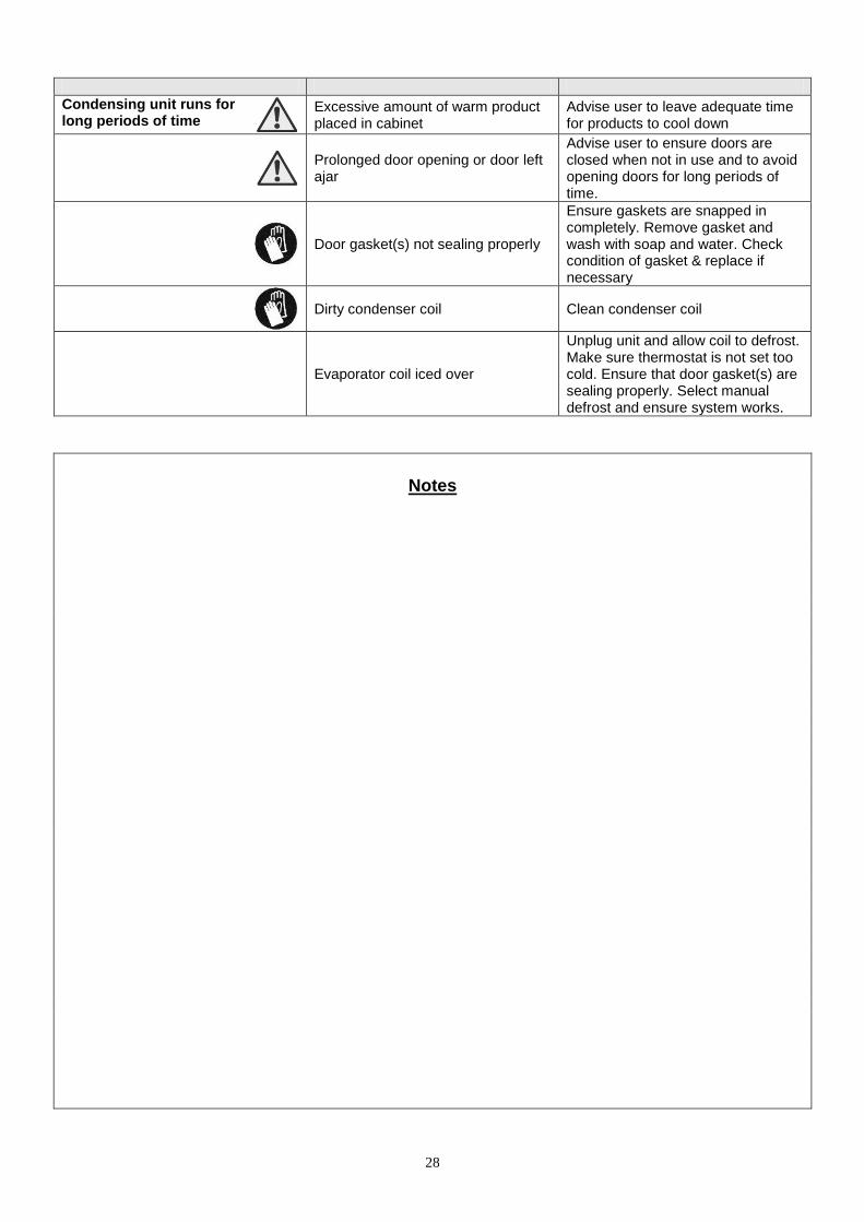
28
Condensing unit runs for long periods of time
Excessive amount of warm product placed in cabinet
Advise user to leave adequate time for products to cool down
Prolonged door opening or door left ajar
Advise user to ensure doors are closed when not in use and to avoid opening doors for long periods of time.
Door gasket(s) not sealing properly
Ensure gaskets are snapped in completely. Remove gasket and wash with soap and water. Check condition of gasket & replace if necessary
Dirty condenser coil Clean condenser coil
Evaporator coil iced over
Unplug unit and allow coil to defrost. Make sure thermostat is not set too cold. Ensure that door gasket(s) are sealing properly. Select manual defrost and ensure system works.
Notes
29
Foster Operations Asia Pacific Contact: Zoe Callender Tel: +44 1553 780502 Fax: +44 1553 768409 Email: [email protected] Middle East Contact: Graham Heath Tel: +971 4 3497 393 Fax: +971 4 3448 232 Email: [email protected] Foster Refrigerator Oldmedow Road Kings Lynn Norfolk PE30 4JU Tel: 01553 780500 Fax: 01553 768409 Website: www.fosterrefrigerator.co.uk Email: [email protected] a Division of „ITW (UK) Ltd‟
F-Series/AT1/2-5/SM/OPS/0611
![Interface with SIBS-AT2 Oracle FLEXCUBE Universal … · Interface with SIBS-AT2 Oracle FLEXCUBE Universal Banking Europe Cluster Release 11.3.81.02.0 [October] [2013]](https://img.pdfslide.us/doc/110x75/5b02e1637f8b9a3c378b5b7a/interface-with-sibs-at2-oracle-flexcube-universal-with-sibs-at2-oracle-flexcube.jpg)