Embed Size (px)
Citation preview
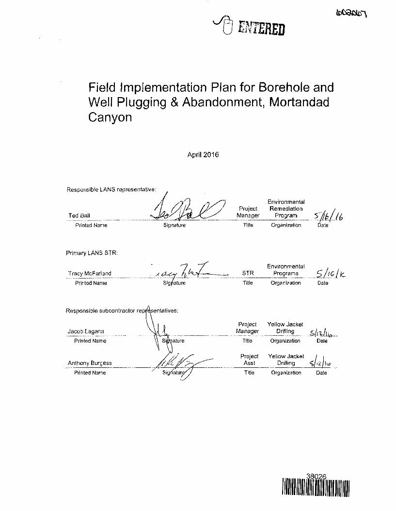
Field Implementation Plan for Borehole and Well Plugging & Abandonment, Mortandad Canyon
Printed Name
Primary LANS STR:
McFarland
Printed Name
April 2016
Responsible subcontractor rep~entatives.
Jacob Lagana Printed Name . - - \ S' al~;~-----··-
//f tf/:.~::----;; ~":;-- ----·---
·~
Printed Name
Anthony Burgess
Project Manager
nua
Environmental Remediation
Program
Organization sJk}J6
Date
Environmental ---~!R _____ P.!ogra~~- ____ $.j_J_c{ le.
Title Organization Date
Project Yellow Jacket ___ M_a:i~ge__r:_ ____ _?rilll~g ___ .... S/, ~--
Title 0111anizalion Date
Project Yellow Jacket ~ Asst Drilhng ~ ,z ll.Gl
' --··--•O»OH "'"'·--Title On~anlzation Date
38026
1111111 lllll lllll ll/1111111 II/I /Ill
April 2016
FIELD IMPLEMENTATION PLAN FOR WELL & BOREHOLE PLUGGING & ABANDONMENT, MORTANDAD CANYON, LOS ALAMOS NATIONAL LABORATORY
Presented by:
Yellow Jacket Drilling Services, LLC
~.A ~· Los Alamos
NATIONAL LABORATORY -EST.1943-
ESHID-602067
Field Implementation Plan for Borehole and Well Plugging & Abandonment, Mortandad Canyon
Responsible LANS representative:
Ted Ball
Printed Name
Primary LANS STR:
Tracy McFarland
Printed Name
Responsible subcontractor rep
Jacob Lagana
Printed Name
Anthony Burgess
Printed Name
Signature
April 2016
Project Manager
Title
STR
Title
Project Manager
Title
Project Asst
Title
Environmental Remediation
Program
Organization
Environmental
Date
Programs 5 IC le Organization Date
Yellow Jacket Drilling
Organization Date
Yellow Jacket .:c;,/.2 ho Drilling
Organization Date
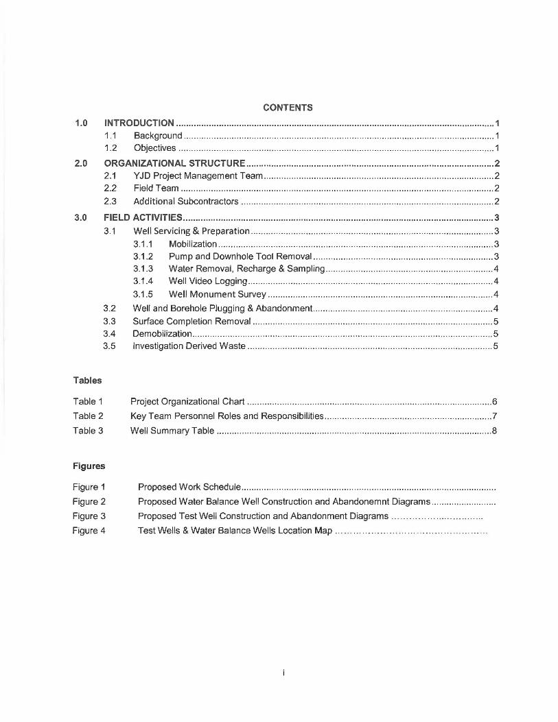
CONTENTS
1.0 INTRODUCTION ............................................................................................................................... 1 1 .1 Background ......... ............... .................. .. .......... .. ......... .. ........ .. .................... ........... .. .............. 1 1.2 Objectives ........... .. ..... .. ......... ..... .. ........ ..... ..... ........ ... ............. ....... ...... ...... ............ .... .. .... .... ... 1
2.0 ORGANIZATIONAL STRUCTURE ................................................................................................... 2 2.1 YJD Project Management Team ..... .. ...... ......... ........... .... .... ... .. ........ ... .. ........ ............. ..... .. .. ... 2 2.2 Field Team ............................................................................................................................. 2
2.3 Additional Subcontractors ....... .. ... ........ ......................................................... ...... .................. 2
3.0 FIELD ACTIVITIES ............................................................................................................................ 3
3.1 Well Servicing & Preparation ..... .. ........ .. ................ ... ... .... .... ........... .... ......... .. ................ ..... ... 3
3.1 .1 Mobilization ....... .......... .............. .......... .. ......... .. ......... .. ......... .. ......... .. .......... .. ........ ... 3 3.1.2 Pump and Downhole Tool Removal .. .. ......... .. .................... .. ............... ...... ... .. ......... 3 3.1.3 Water Removal, Recharge & Sampling ......... ... ................ .. ............. .................... .. . .4 3.1.4 Well Video Logging ..... .. ............................... .. ...................... .......... .. ........................ 4
3.1.5 Well Monument Survey ............... .. .... ..... ... .................. .... ... .... .... ............... ...... .. ... .. 4
3.2 Well and Borehole Plugging & Abandonment... ...................... ... .................... .. ......... .. .......... .4
3.3 Surface Completion Removal ................................................................................................ 5 3.4 Demobilization ........ ........................................... .. ..................... .......... .............................. .... .. 5 3.5 Investigation Derived Waste .. .. ... ........ ... .............. .... ... ..... .. .. .. .. ... ...... .... ..................... .... ....... . 5
Tables
Table 1
Table 2
Table 3
Figures
Figure 1
Figure 2
Figure 3
Figure 4
Project Organizational Chart ....... ... .. .. ..... ... ... ..... .. .. ... .. ...... ... ....... ......... ......... .. .. ......... .... .... .... 6
Key Team Personnel Roles and Responsibilities .................... ............................................... 7
Well Summary Table ............................. .. ........ ................................................. ...... ..... ...... ..... 8
Proposed Work Schedule ..... .. ... ...... .. ........ .. .. ........... ................... .. .... ........ ........... ...... ........ .. .
Proposed Water Balance Well Construction and Abandonemnt Diagrams ........................ ..
Proposed Test Well Construction and Abandonment Diagrams ...... .... ...... ... .. .. . ....... .
Test Wells & Water Balance Wells Location Map .... .. ....... .. ..... . .... .. .. ... .. .... .... ... ... .. .
F/P for Well Plugging and Abandonment Mortandad Canyon
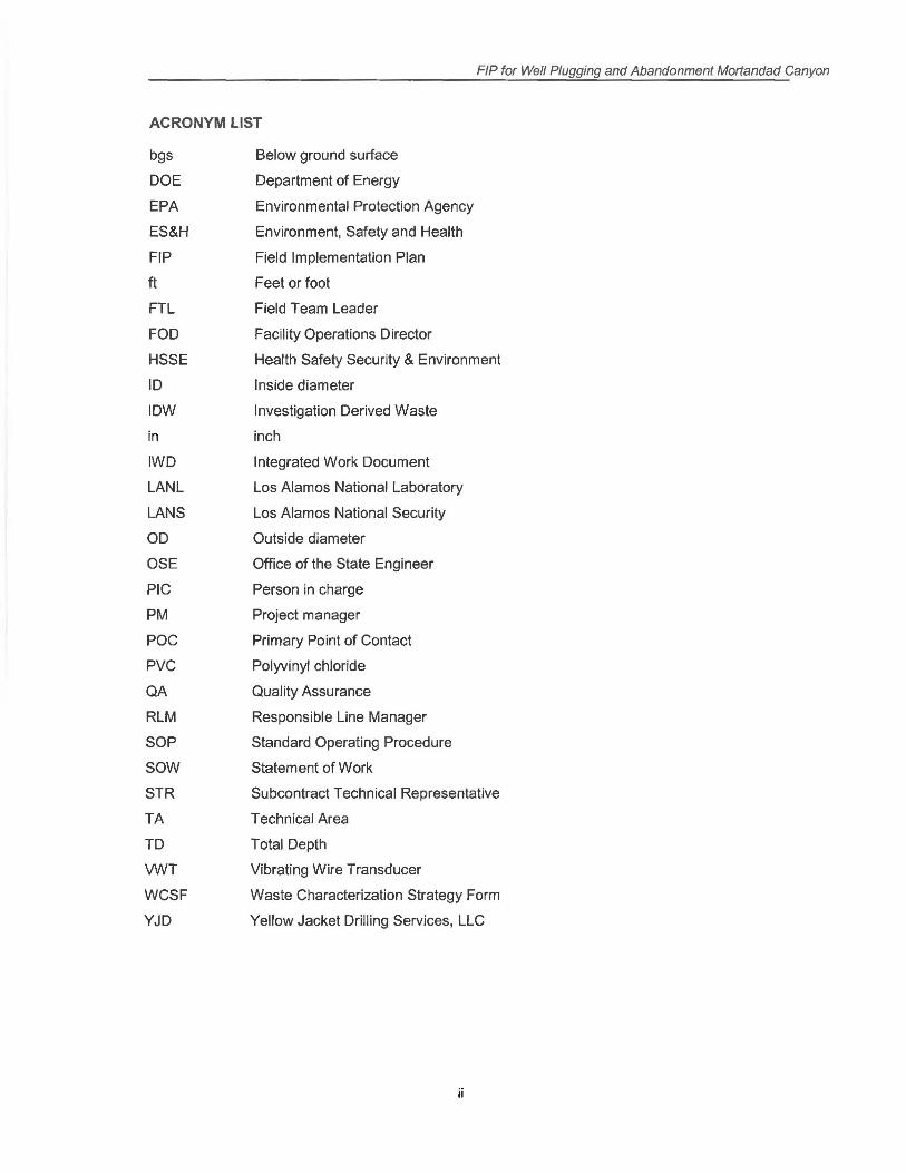
ACRONYM LIST
bgs Below ground surface
DOE Department of Energy
EPA Environmental Protection Agency
ES&H Environment, Safety and Health
FIP Field Implementation Plan
ft Feet or foot
FTL Field Team Leader
FOO Facility Operations Director
HSSE Health Safety Security & Environment
ID Inside diameter
IDW Investigation Derived Waste
in inch
IWD Integrated Work Document
LANL Los Alamos National Laboratory
LANS Los Alamos National Security
OD Outside diameter
OSE Office of the State Engineer
PIC Person in charge
PM Project manager
POC Primary Point of Contact
PVC Polyvinyl chloride
QA Quality Assurance
RLM Responsible Line Manager
SOP Standard Operating Procedure
sow Statement of Work
STR Subcontract Technical Representative
TA Technical Area
TD Total Depth
VWT Vibrating Wire Transducer
WCSF Waste Characterization Strategy Form
YJD Yellow Jacket Drilling Services, LLC
ii
FJP for Well Plugging and Abandonment Mortandad Canyon
1.0 INTRODUCTION
1.1 Background
Yellow Jacket Drilling Services, LLC (Y JD) has been contracted to perform a total of twenty six (26) well abandonments by Los Alamos National Security (LANS) Environmental management (EM) Directorate. Four (4) wells have been designated as MT Test Wells, twenty one wells (21) Water Balance Wells and one (1) hole designated 50-603060. All wells are located within Los Alamos National Laboratory (LANL), Mortandad Canyon, located in Los Alamos County, New Mexico. Hole 50-603360 is located on the mesa top south of Pajarito Rd, in Technical Area 50.
The wells designated MCWB 4 thru 9b are constructed of 3 inch Sch 40 PVC up to depths of 80 feet bgs. (drilled in 1994); wells designated MT 1 thru 4 are constructed of 2 inch Sch 40 PVC up to depths of 75 feet bgs. (drilled in 1998); and hole designated 50-603060 (drilled in February 2008) are to be plugged and abandoned. This work will be performed under the statement of work (SOW) provided by RFP 1578464, dated February 26, 2016, LANS and the Work Plans for the Plugging & Abandonment of wells for Fiscal year 2016, LA-UR-16-2024, EP2015-0212, January 2016.
In general, twenty five (25) environmental monitor wells will be decommissioned by the following process; all pumps and down hole equipment will be removed, any water present will be removed and contained, well video (as required), followed by water sample collection (as required) 24 hours later, wells will be grouted in place by tremie pumping materials, followed by over drilling of the upper 20 feet of PVC well casing and cementing in the upper 20 feet of hole. After all well plugging actives are completed any above ground well features shall be removed as required. Upon completion of all decommissioning activities a monument shall be placed and surveyed.
YJD shall provide means and oversight for investigation derived waste (IDW) containment and on site management, Office of the State Engineer of New Mexico (NMOSE) plugging and abandonment documentation and required State submittals, and all required documentation set forth by the SOW.
This Field Implementation Plan (FIP) provides guidance for well servicing (including pump removal, water bailing & collection, video, etc.), well plugging & abandonment (in-place grouting & over drilling of upper 20 feet of PVC casing). and surface completion removals . Project staff, health and safety, waste management, security, schedules, and required permits are also discussed in this document.
1.2 Objectives
As stated in the Work Plans for the Plugging & Abandonment of wells for Fiscal year 2016, LAUR-16-2024, EP2015-0212, January 2016, the purpose of the FIP= is to address activities required to complete the general scope of work that will establish a provision of the technical functions and expertise required for the effective and timely delivery of professional services to plug and abandon wells and boreholes for project. These services shall be in accordance with the NMOSE and Compliance Order on Consent.
The purpose for the SOW is for plugging and abandonment of wells to prevent the migration of surface water and potential contaminants within the wells to depth. A Waste Characterization Strategy Form (WCSF) has been prepared and a final Summary Report will be prepared for LANL.
1 April 2016
F/P for Well Plugging and Abandonment Mortandad Canyon
2.0 ORGANIZATIONAL STRUCTURE
This project is being performed by Y JD for LANS EM Directorate. The LANL Environmental Programs Drilling Subcontract Technical Representative (STR) will be YJD's focal point for communications and Y JD's project manager will the main point of contact.
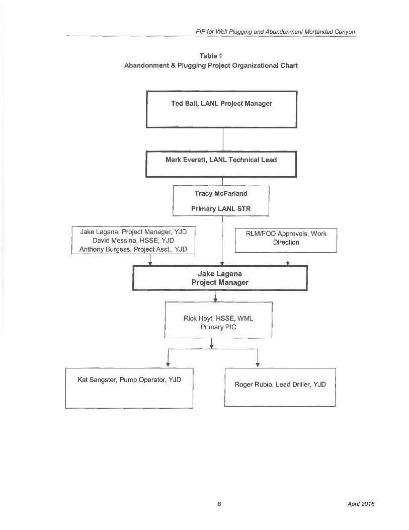
An organizational chart is presented in Table 1.
2.1 YJD Project Management Team
The YJD Management Team consists of the Project Manager (PM), Field Geologist, two (2) Environment, Safety and Health (ES&H) Repiesentatives, and Project Manager Assistant. The Management Team will review all task order work plans, ensure compliance with quality assurance (QA), ES&H plans, and perform project requirements of ongoing work.
The Management Team will also provide technical assistance to the Field Team . In addition, they will provide health and safety oversight and quality control guidance for plugging and abandonment process.
The ES&H Representative will provide health and safety related technical assistance and senior review of all project specific safety plans. He will also conduct project site safety inspections. The YJD and LANS Management Team key personnel and their respective roles are detailed in Table 2.
2.2 Field Team
YJD's field team personnel and their respective roles are shown in Table 2. This staff is primarily consisting of pump rig operator and an assistant, drill rig operator and up to two (2) assistants, IDW coordinator and additional qualified staff may be added as necessary to ensure all project requirements are met. These staff will be identified and their roles assigned before work begins.
During the abandonment operations, the main point of contact for field activates will be our Field Health, Safety Security & Environment officer (HSSE) I Waste Management Leader (WML) and there will be at least one operator (drill rig and/or pump rig operator) onsite full time to assist the Field Team Leader {FTL)/Person in Charge (PIC). Other YJD team members will assist the FTL I PIC as needed. The lead operators will maintain field notes detailing daily site activities, compile and submit daily field reports, document down-hole tools and type/quantity of materials used during abandonment activities, maintain and document well data tallies, collect samples, document wastes generated, and conduct daily safety meetings and equipment inspections. The FTL/PIC will be the main point of contact at the site.
Field operations will run approximately 12-hours a day, on a 10 day on I 4 day off shift rotation . Shift timing is yet to be determined. Y JD field team members will be interchangeable and their exact scheduling is expected to be flexible.
2.3 Additional Subcontractors
At this time, no major subcontractors are anticipated to be utilized for any major aspects of this SOW. Subcontractors will be utilized throughout the project but not for any major task such as; downhole well servicing items (pump removal, water removal & sampling) or drilling & well decommissioning activities.
2 April 2016
FIP for Well Plugging and Abandonment Mortandad Canyon
3.0 FIELD ACTIVITIES
Field activities, including well servicing (including pump removal, water bailing & collection, video, etc.), well plugging & abandonment (in-place grouting and over drilling of upper 20 feet of PVC casing), and surface completion removal will follow an approved Integrated Work Document (IWD). The Work Plans for the Plugging & Abandonment of wells for Fiscal year 2016, LA-UR-16-2024, EP2015-0212, January 2016 will be used to guide field operations and ensure all objectives are met.
Field activities shall commence and attempt to follow the attached "projected work schedule", this schedule serves as outline for Y JD's intended performance timeline for the SOW. Y JD shall make all attempts practical and reasonable to maintain the schedule set forth in order to maintain the contract schedule set for by LANL. Y JD will keep LANL informed to their progress and maintain an updated weekly, project schedule.
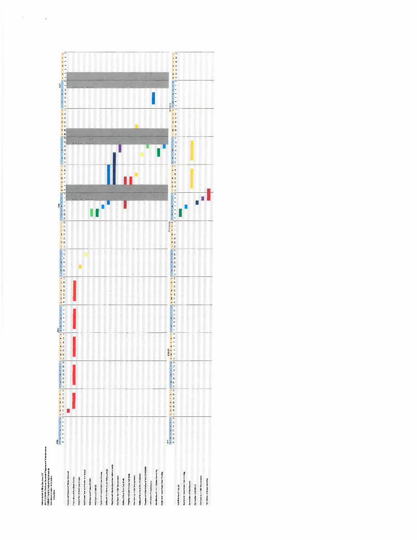
A current Subcontractor Schedule for this project is presented in Figure 1.
3.1 Well Servicing and Well Preparation
Pump Rig, Drilling Rig and other associated equipment and supplies for the completion of the project will be staged around the work site in an organized and secure manner. Surplus and/or inactive equipment and supplies may be stored at the LANL project laydown yard (this area is to be determined by LANS). The STR, FTL, and drilling foreman will control the gate key.
3.1.1 Mobilization
Mobilization will consist of multiple events transporting and setting up equipment at the project location. Mobilization will include the following:
• Mobilize pump and drill rig, trailers (if necessary), support vehicles, abandonment tools and materials, and related ancillary supplies and equipment to the drill site.
• Stage alternative rigs, equipment, tools and materials at the laydown yard.
• Entrance/exit radiological screening of all equipment and tooling by RP-1. Perform all on site safety training, inspection of equipment and tooling prior to commencing work.
• Set up drill rig , trailers, support vehicles and tools at the designated location.
• Review scope of work and project-specific health and safety issues with crew.
• Complete all required training for all personnel.
• Obtain Facility Operations Director (FOO) Work Authorization, including rig inspection and IWD review.
The site will be accessed from south of Pajarito Rd. The water source for the project has been identified as a fire hydrant near the Pajarito yard on E. Pajarito Rd.
3.1 .2 Pump and Downhole Supplies Removal
Prior to the plugging and abandonment, all wells shall have all pumps, transducers, sounding tubes and other downhole equipment and tooling removed. A standard small capacity pump rig
3 April 2016
F/P for Well Plugging and Abandonment Mortandad Canyon
shall be utilized to remove all downhole equipment at twenty three (23) of the locations. The two remaining wells shall have this service performed by the drill rig due to location and access.
All materials and equipment removed shall be staged at a designated location for LANL or disposed of as part of the WCSF. IDW accumulated during pump removal activities will be staged on site and characterized as determined by the WCSF.
The Work Plans for the Plugging & Abandonment of wells for Fiscal year 2016, LA-UR-16-2024, EP2015-0212, January 2016 will be used to guide field operations and ensure all objectives are met.
3.1.3 Groundwater Removal, Recharge and Sampling
After all downhole equipment has been removed, the well will be checked for the presence of groundwater and the static (alluvial) water level (SWL) will be measured if present. Wells that have water present shall be bailed dry (or as close to practical) and shall be allowed to recharge for up to 24 hours. After the 24 hour period if water is present, a sample shall be collected by bailer and procured for analysis. All samples will be submitted to LAN L's Sample Management Office (SMO) with the corresponding chain of custody and any other required documentation. IDW accumulated during these activities will be staged on site and characterized as determined by the WCSF.
3.1.4 Well Video Logging
Some of the wells and bore hole may be video logged by a portable downhole camera by LANL prior to Y JD's arrival at LANL. While providing a vertical view and depth counter, the well shall be videoed and recorded to a Scan Disk. A copy of any wells' recording shall be made available upon request. This video will ensure no obstructions are present prior to the plugging and abandonment procedure.
3.1.5 Well Monument Survey
All well monuments shall be surveyed and data shall be provided to LANL in the final summary report. A global positioning system (GPS) hand held unit shall be utilized for determination of each well's northing, easting and elevation data. Coordinates shall be provided with respect to the North American Datum (NAD83).
3.2 Well Plugging and Abandonment
Upon completion of activities outlined in section 3.1 , the plugging and abandonment of twenty five (25) wells shall be performed in accordance with the NMOSE approved plugging and abandonment plans for each well . In addition, all work will follow The Work Plans for the Plugging & Abandonment of wells for Fiscal year 2016, LA-UR-16-2024, EP2015-0212, January 2016 as a guide field operations and ensure all objectives are met. A standard truck mounted hollow stem auger rig shall be utilized for the abandonment procedures. This will include tremie pumping materials from the bottom of the well up to the surface to ensure displacement of any water and provide a complete seal without any voids. After well has been grouted in place, over drilling of the upper twenty (20) feet of PVC casing shall performed, then a seal shall be placed within the over drilled borehole to complete sealing of the abandoned well. Should any settlement of grouting materials take place, the wells will be "topped off' the following day to ensure complete sealing prior to commencing with surface completion removal and restorations.
4 April 2016
FIP for Well Plugging and Abandonment Mortandad Canyon
IDW accumulated during these activities will be staged on site and characterized as determined by the WCSF.
3.3 Surface Completion Removal & Restoration
The existing wellhead surface completion including any above ground service devices (such as; control panels, wiring, etc.), well vaults or monuments, bollards and concrete well pads shall be removed. IDW accumulated during plugging and abandonment activities will be staged on site and characterized as determined by the WCSF.
A brass survey monument, imprinted with well identification information, will be placed in the northwest corner of the pad. Wellhead surface completions will be deconstructed in accordance with The Work Plans for the Plugging & Abandonment of wells for Fiscal year 2016, LA-UR-16-2024, EP2015-0212, January 2016.
3.4 Demobilization
Demobilization activities will include:
• Final decontamination and screening for radioactivity by RP-1 of the drill rig, tools, and support equipment.
• Loading and removal of the drilling tools, including alternative tools, from the site.
• Removal of the pump rig, drill rig and all support vehicles & equipment from the site.
• Staging and securing of IDW for future disposition.
• Removal of municipal waste (e.g. materials packaging).
• Final site cleanup.
The LANL STR will inspect the site prior to final demobilization of the drill crew. Final demobilization of the drill crew will not be permitted until the condition of the site is acceptable to the STR.
3.5 Investigation Derived Waste
IDW will be managed in accordance with an approved WCSF. This procedure incorporates the requirements of all applicable EPA and NMED regulations, DOE orders and Laboratory requirements. The primary waste streams include drill cuttings, groundwater and, potentially, decontamination water and typical construction debris. Drill cuttings will be managed in accordance with the WCSF which will be prepared by LANL in accordance with EP-DIR-SOP-10021, Characterization and Management of Project Waste, and will provide more detailed information on waste descriptions, quantities, handling, and disposition. All wastes generated during the Mortandad Plugging and Abandonment project will be managed according to the WCSF.
5 April 2016
FIP for Well Plugging and Abandonment Mortandad Canyon
Table 1 Abandonment & Plugging Project Organizational Chart
Ted Ball, LANL Project Manager
Mark Everett, LANL Technical Lead
Tracy Mcfarland
Primary LANL STR
Jake Lagana, Project Manager, Y JD RLM/FOD Approvals, Work David Messina, HSSE, Y JD Direction
Anthony Burgess, Project Asst., Y JD
i ' i Jake Lagana
Project Manager
1
Rick Hoyt, HSSE, WML Primary PIC
i J l
Kat Sangster, Pump Operator, Y JD Roger Rubio, Lead Driller, Y JD
6 April 2016
FIP for Well Plugging and Abandonment Mortandad Canyon
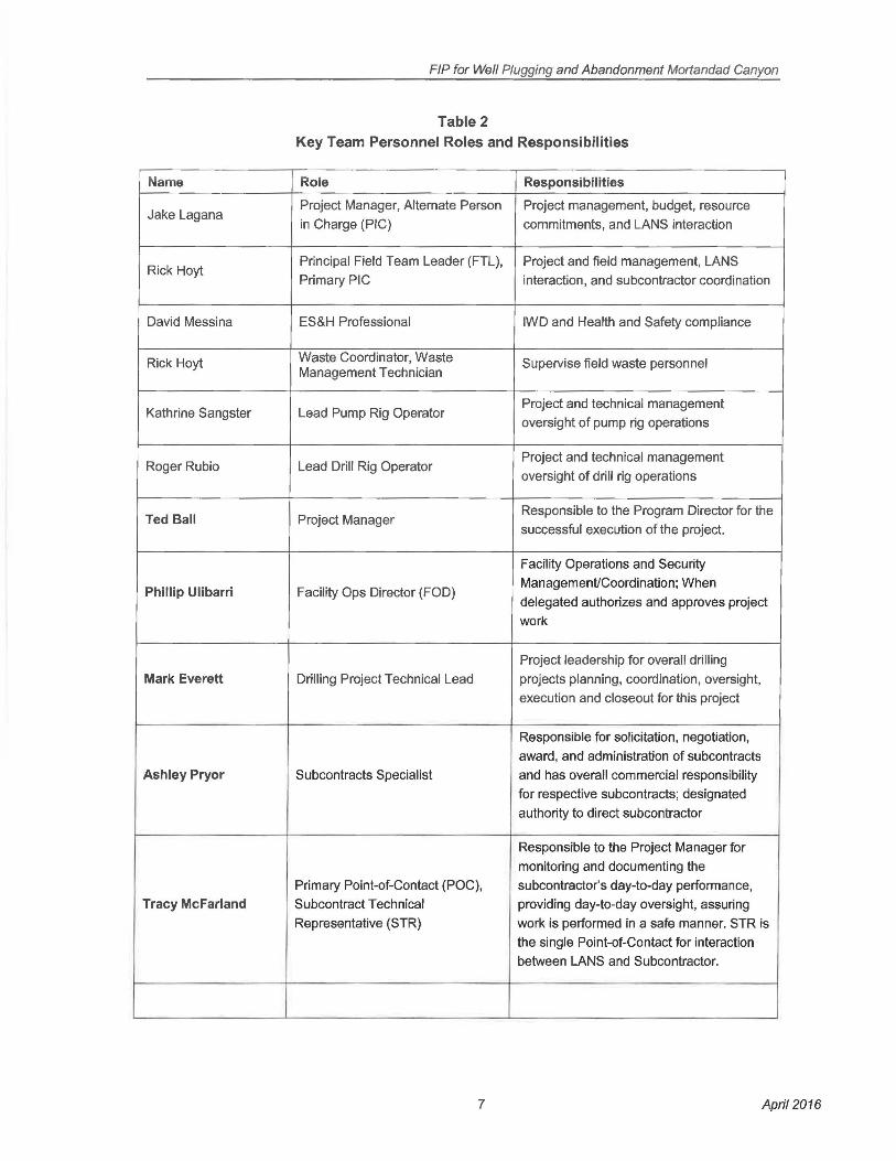
Table 2 Key Team Personnel Roles and Responsibilities
Name Role Responsibilities
Jake Lagana Project Manager, Alternate Person Project management, budget, resource
in Charge (PIC) commitments, and LANS interaction
Rick Hoyt Principal Field Team Leader (FTL), Project and field management, LANS
Primary PIC interaction, and subcontractor coordination
David Messina ES&H Professional IWD and Health and Safety compliance
Rick Hoyt Waste Coordinator, Waste Supervise field waste personnel Management Technician
Kathrine Sangster Lead Pump Rig Operator Project and technical management
oversight of pump rig operations
Roger Rubio Lead Drill Rig Operator Project and technical management
oversight of drill rig operations
Ted Ball Project Manager Responsible to the Program Director for the
successful execution of the project.
Facility Operations and Security
Phillip Ulibarri Facility Ops Director (FOO) ManagemenVCoordination; When
delegated authorizes and approves project
work
Project leadership for overall drilling
Mark Everett Drilling Project Technical Lead projects planning, coordination, oversight,
execution and closeout for this project
Responsible for solicitation, negotiation,
award, and administration of subcontracts
Ashley Pryor Subcontracts Specialist and has overall commercial responsibility
for respective subcontracts; designated
authority to direct subcontractor
Responsible to the Project Manager for
monitoring and documenting the
Primary Point-of-Contact (POC), subcontractor's day-to-day performance,
Tracy McFarland Subcontract Technical providing day-to-day oversight, assuring
Representative (STR) work is performed in a safe manner. STR is
the single Point-of-Contact for interaction
between LANS and Subcontractor.
7 April 2016

FJP for Well Plugging and Abandonment Mortandad Canyon
Table 3 Test Wells & Water Balance Wells Chart
8 April 2016
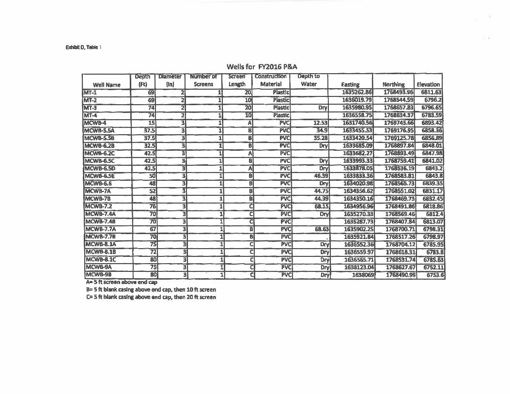
Extiblt 0, Table t
uepm Diameter numoeror Well Name (Ft) (In) Screens
MT-1 69 2 MT-2 69 2 MT-3 74 2 MT-4 74 2 MCWB-4 15 3 MCWB-5.SA 37.5 3 MCWB-S.58 37.5 3 MCWIHi.28 32.5 3 MCWB-6.X 42.S 3 MCWB-6.5C 42.5 3 MCWB-6.50 42.5 3 , MCWB-6.SE so 3 MCWB-6.6 48 3 MCWB-7A 52 3 MCWB-78 48 3 MCWB-7.2 76 3 MCWB-7.4A 70 3 MCWB-7.48 70 3 MCWB-7.7A 67 3 MCWB-7.78 70 3 MCWB-8.JA 75 3 MCWB-8.18 72 3 MCWIHUC 80 3 MCWB-9A 75 3 MCWB-98 80 3 . - .. .:... -~-- -- _......__ . -- - cap
B= 5 ft blank caslna above end cap. then 10 ft screen C= s ft blank casrne above end cap. then 20 ft screen
1 1 1 1 1 1 1 1 1 1 1 1 1
1 1 1 1 1 1 1 1 1 1 1 1
Wells for FY2016 P&A :x:reen -·-··--· uepmw Length Material Water Easting Northing Elevation
20 Piastlc 1635262.86 1768493.96 6811.63 10 Plastlc 1636019.79 1768544.59 67962 20 Plastic Ory 1635980.95 1768657.83 6796.65 10 Plastic 1636558.75 1768634.37 6783.59 A PVC 12.53 16317~ 1769745.tit 6893.42 B PVC 34.9 1633455.53 1769176.95 6858.36 B PVC 35.28 1633420.54 1769125.78 6856.89 B PVC Dry 1633685.09 1768897.84 6848.01 A PVC 1633682.27 1768893.49 6847.98 B PVC Dry 1633993.33 1768759.41 6841.02 A PVC Dry 1633878.05 1768536.19 6843.2 8 PVC 46.39 1633833.:H 1768583.81 6843.8 B PVC Dfy 1634020.98 1768565.73 6839.35 B PVC 44.75 1634356.62 1768551.02 6831.17 B PVC 44.39 1634350.16 1768469.73 6832.45 c PVC 68.15 1634956.96 1768491.86 6818.86 c PVC Dry 1635270.33 1768569.46 6812.4 c PVC 1635287.73 1768407.84 6813.07 B PVC 68.63 1635902.25 1768700.71 679831 B PVC . 1635921.84 1768517.26 6798.97 c PVC Dry 1636552.36 1768704.12 6785.95 c PVC Dry 1636559.97 1768618.31 6783.8 c PVC Dry 1636565.71 1768531.74 6785.63 c PVC Dry 1638123.04 1768627.67 6752.11 c PVC Dry 1638069 1768490.99 6753.E

FIP for Well Plugging and Abandonment Mortandad Canyon
Figure 1 Proposed work Schedule
9 April 2016
..
~ ~ ~""-............... --=------.;....1...:....;,,_,,. f ~ :·~:,--~~~~~~~~~~~~~~~~~~-I:~:~~~~~~~
..
...
-·
-' _,
I I I
I
f I i i j ] j I f t I
I I
•• .. I
-· .. -' . " "' ., ..
.. . , _,
., ..
_,
FIP for Well Plugging and Abandonment Mortandad Canyon
Figure 2 Water Balance Well Construction & Abandonment Diagram
10 April 2016
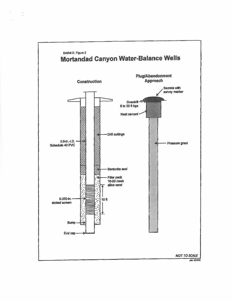
Exhibit D, Figure 2
Mortandad Canyon Water-Balance Wells
Construction
3.D-fn.-1.D. Schedule 40 PVC
Plug/Abandonment Approach
Overdril Ota 20ftbgs
Neat cement
Drill cuttingl
Bemnite aeal
Fiiier peck 10.20meth allca sand
/ Sacntte wllh ~ survey marfcer
...,_ PmaUre grout
NOTTO SCALE plnl 12t811i
FIP for Well Plugging and Abandonment Mortandad Canyon
Figure 3 Test Wells Construction & Abandonment Diagram
11 April 2016
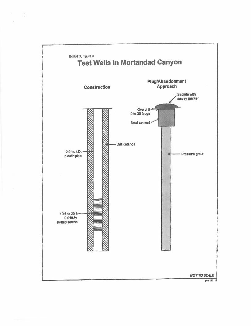
Exhlb~ 0, Flgll1'8 3
Test Wells in Mortandad Canyon
2.0-ln.-1.0. plaaUcplpe
Construction
10ft to 201'-~~~ 0.010-ln.
slotted ecreen
Plug/Abandonment Approach
Overdrlll o to 20fl bga
Neat cement
Drll cultlngl
/Secrete with I? survey marker
NOTTO SCALE .,..,Z11tll

FIP for Well Plugging and Abandonment Mortandad Canyon
Figure 4 Test Wells & Water Balance Wells Location Map
12 April 2016
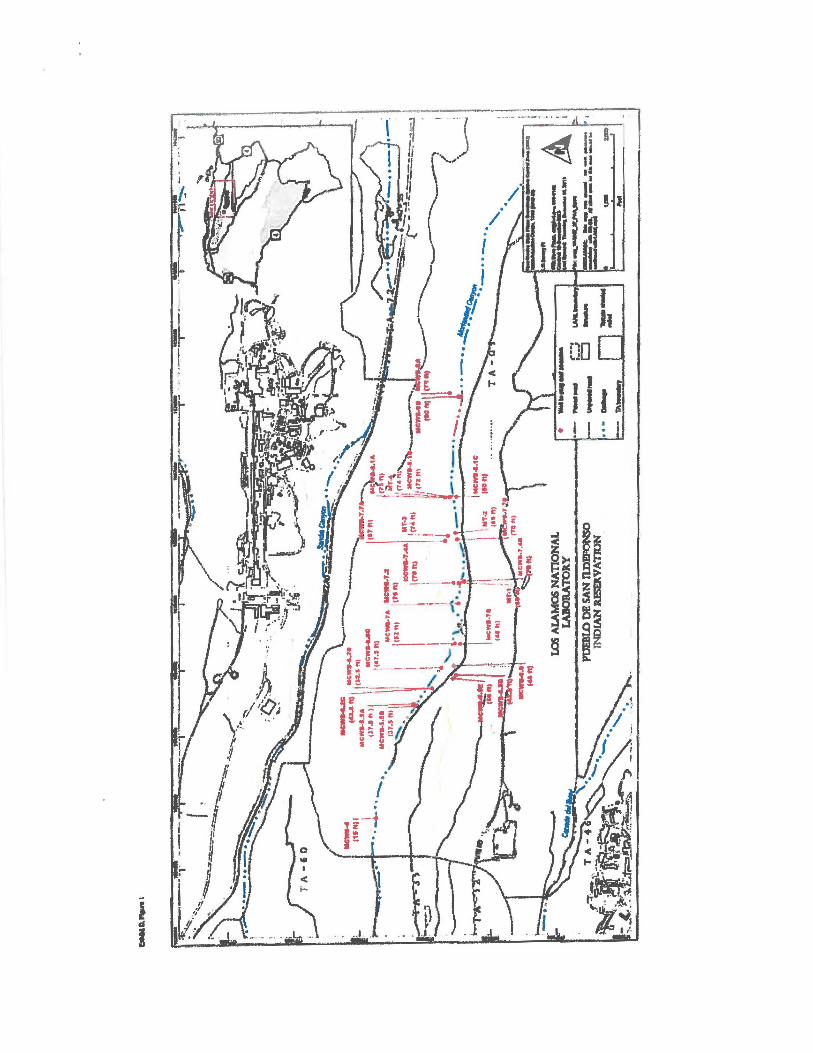
I d
I
I~ t
. .. I .
=-t lz • £ •