Embed Size (px)
Citation preview
Modeling safety and security, state of the art
F. A. Maestas Applied Research Associates, Inc., USA
Abstract
The accurate modeling of complex physical events is critical in evaluating measures for designing and protecting human safety. This paper describes current techniques for modelling key aspects of vehicle, building and human response to extreme events. The terrorist act results in high pressure and temperature environments that apply loads over short time durations. Those loads must be accounted for in the design of building structures, protective vehicles and protective safety equipment. Examples associated with designs to mitigate progressive collapse, occupant injury in vehicle roll over and brain injury will be presented. Key aspects of the modelling will be discussed. Engineering models will be the focus of the paper although some finite element techniques will be also provided Keywords: weapon effectiveness, survivability analysis, modeling and simulation, physical security analysis, persona security.
1 Introduction
In recent years, physical security and force protection specialists have been obligated to make costly and potentially life-saving decisions regarding blast mitigation strategies associated with equipment, structural designs and retrofits, site planning, and security protocols for increasingly complex environments and in response to increasingly aggressive adversaries. Typically, Improvised Explosive Devices (IEDs) have increasingly been the preferred means for terrorists to achieve their objectives. The increased use of both conventional and thermobaric weapons is motivating new and innovative efforts within research, development, and medical communities to offer near- and long-term improvements in vehicle design, structural design and personnel protective gear. Figure 1 merely is a fireball surrounding a vehicle as the result of an IED detonation.
Safety and Security Engineering IV 487
www.witpress.com, ISSN 1743-3509 (on-line) WIT Transactions on the Built Environment, Vol 117, © 2011 WIT Press
doi:10.2495/SAFE110421
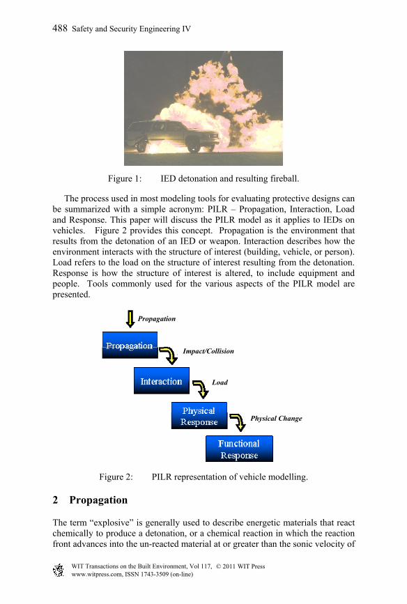
Figure 1: IED detonation and resulting fireball.
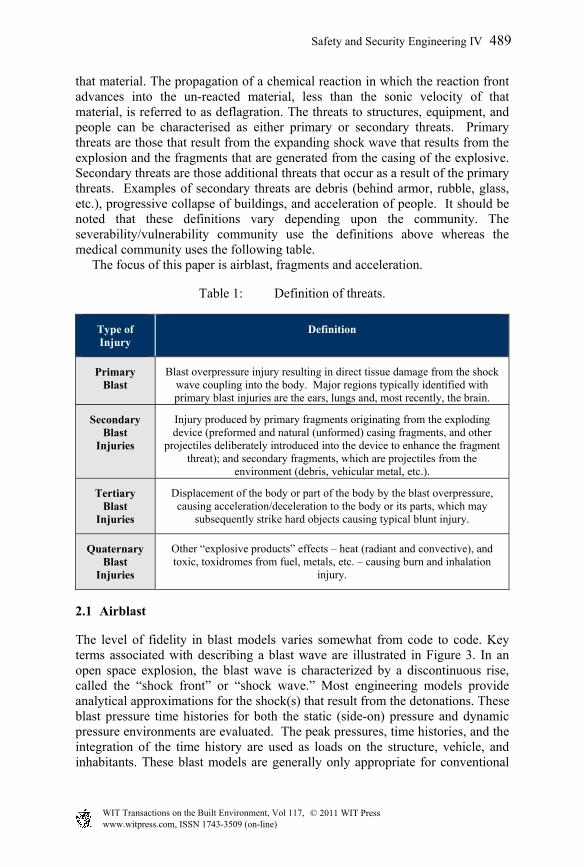
The process used in most modeling tools for evaluating protective designs can be summarized with a simple acronym: PILR – Propagation, Interaction, Load and Response. This paper will discuss the PILR model as it applies to IEDs on vehicles. Figure 2 provides this concept. Propagation is the environment that results from the detonation of an IED or weapon. Interaction describes how the environment interacts with the structure of interest (building, vehicle, or person). Load refers to the load on the structure of interest resulting from the detonation. Response is how the structure of interest is altered, to include equipment and people. Tools commonly used for the various aspects of the PILR model are presented.
Figure 2: PILR representation of vehicle modelling.
2 Propagation
The term “explosive” is generally used to describe energetic materials that react chemically to produce a detonation, or a chemical reaction in which the reaction front advances into the un-reacted material at or greater than the sonic velocity of
Propagation
Impact/Collision
Load
Physical Change
488 Safety and Security Engineering IV
www.witpress.com, ISSN 1743-3509 (on-line) WIT Transactions on the Built Environment, Vol 117, © 2011 WIT Press
that material. The propagation of a chemical reaction in which the reaction front advances into the un-reacted material, less than the sonic velocity of that material, is referred to as deflagration. The threats to structures, equipment, and people can be characterised as either primary or secondary threats. Primary threats are those that result from the expanding shock wave that results from the explosion and the fragments that are generated from the casing of the explosive. Secondary threats are those additional threats that occur as a result of the primary threats. Examples of secondary threats are debris (behind armor, rubble, glass, etc.), progressive collapse of buildings, and acceleration of people. It should be noted that these definitions vary depending upon the community. The severability/vulnerability community use the definitions above whereas the medical community uses the following table. The focus of this paper is airblast, fragments and acceleration.
Table 1: Definition of threats.
Type of Injury
Definition
Primary Blast
Blast overpressure injury resulting in direct tissue damage from the shock wave coupling into the body. Major regions typically identified with primary blast injuries are the ears, lungs and, most recently, the brain.
Secondary Blast
Injuries
Injury produced by primary fragments originating from the exploding device (preformed and natural (unformed) casing fragments, and other
projectiles deliberately introduced into the device to enhance the fragment threat); and secondary fragments, which are projectiles from the
environment (debris, vehicular metal, etc.).
Tertiary Blast
Injuries
Displacement of the body or part of the body by the blast overpressure, causing acceleration/deceleration to the body or its parts, which may
subsequently strike hard objects causing typical blunt injury.
Quaternary Blast
Injuries
Other “explosive products” effects – heat (radiant and convective), and toxic, toxidromes from fuel, metals, etc. – causing burn and inhalation
injury.
2.1 Airblast
The level of fidelity in blast models varies somewhat from code to code. Key terms associated with describing a blast wave are illustrated in Figure 3. In an open space explosion, the blast wave is characterized by a discontinuous rise, called the “shock front” or “shock wave.” Most engineering models provide analytical approximations for the shock(s) that result from the detonations. These blast pressure time histories for both the static (side-on) pressure and dynamic pressure environments are evaluated. The peak pressures, time histories, and the integration of the time history are used as loads on the structure, vehicle, and inhabitants. These blast models are generally only appropriate for conventional
Safety and Security Engineering IV 489
www.witpress.com, ISSN 1743-3509 (on-line) WIT Transactions on the Built Environment, Vol 117, © 2011 WIT Press
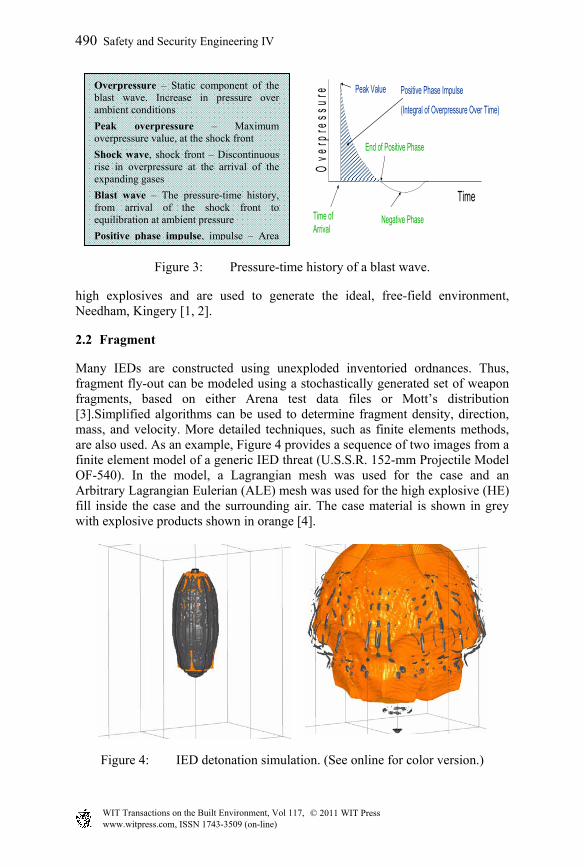
Figure 3: Pressure-time history of a blast wave.
high explosives and are used to generate the ideal, free-field environment, Needham, Kingery [1, 2].
2.2 Fragment
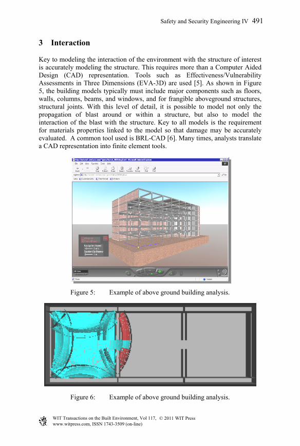
Many IEDs are constructed using unexploded inventoried ordnances. Thus, fragment fly-out can be modeled using a stochastically generated set of weapon fragments, based on either Arena test data files or Mott’s distribution [3].Simplified algorithms can be used to determine fragment density, direction, mass, and velocity. More detailed techniques, such as finite elements methods, are also used. As an example, Figure 4 provides a sequence of two images from a finite element model of a generic IED threat (U.S.S.R. 152-mm Projectile Model OF-540). In the model, a Lagrangian mesh was used for the case and an Arbitrary Lagrangian Eulerian (ALE) mesh was used for the high explosive (HE) fill inside the case and the surrounding air. The case material is shown in grey with explosive products shown in orange [4].
Figure 4: IED detonation simulation. (See online for color version.)
Overpressure – Static component of the blast wave. Increase in pressure over ambient conditions
Peak overpressure – Maximum overpressure value, at the shock front
Shock wave, shock front – Discontinuous rise in overpressure at the arrival of the expanding gases
Blast wave – The pressure-time history, from arrival of the shock front to equilibration at ambient pressure
Positive phase impulse, impulse – Area
Ove
rpre
ssur
e
TimeTime of Arrival
Peak Value
End of Positive Phase
Negative Phase
Positive Phase Impulse
(Integral of Overpressure Over Time)
490 Safety and Security Engineering IV
www.witpress.com, ISSN 1743-3509 (on-line) WIT Transactions on the Built Environment, Vol 117, © 2011 WIT Press
3 Interaction
Key to modeling the interaction of the environment with the structure of interest is accurately modeling the structure. This requires more than a Computer Aided Design (CAD) representation. Tools such as Effectiveness/Vulnerability Assessments in Three Dimensions (EVA-3D) are used [5]. As shown in Figure 5, the building models typically must include major components such as floors, walls, columns, beams, and windows, and for frangible aboveground structures, structural joints. With this level of detail, it is possible to model not only the propagation of blast around or within a structure, but also to model the interaction of the blast with the structure. Key to all models is the requirement for materials properties linked to the model so that damage may be accurately evaluated. A common tool used is BRL-CAD [6]. Many times, analysts translate a CAD representation into finite element tools.
Figure 5: Example of above ground building analysis.
Figure 6: Example of above ground building analysis.
Safety and Security Engineering IV 491
www.witpress.com, ISSN 1743-3509 (on-line) WIT Transactions on the Built Environment, Vol 117, © 2011 WIT Press
3.1 Airblast
The free field blast environment is significantly modified as it interacts with the structure of interest. Figure 6 illustrates the blast environment resulting from a detonation inside a room. Note the shock waves reflecting off the various surfaces of the room. Such reflections significantly affect the load on the surfaces, contents, and personnel inside the room.
3.2 Fragment
When an IED is constructed of a cased munition, fragment loading the structure of interest has two effects. First, they impart momentum to the structure. For vehicles, this momentum contributes to the overall displacement. Second, fragments may penetrate and potentially perforate the structure. Fragment perforation into a building or vehicle results in not only primary fragments, but secondary debris into the interior of the building or vehicle. Because the fragment penetration occurs at a slower rate than the blast loading, the breaches in the vehicle or building structure created by fragment penetration do not significantly facilitate blast wave propagation into the building or vehicle interior. Fragment penetration can be calculated using tools such as FATEPEN [7]. The significance of fragment penetration into the interior is the threat of penetration injuries to occupants.
3.3 Acceleration
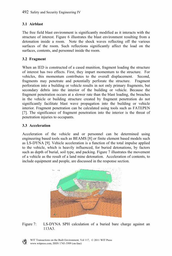
Acceleration of the vehicle and or personnel can be determined using engineering based tools such as BEAMS [8] or finite element based models such as LS-DYNA [9]. Vehicle acceleration is a function of the total impulse applied to the vehicle, which is heavily influenced, for buried detonations, by factors such as depth of burial, soil type, and packing. Figure 7 illustrates the movement of a vehicle as the result of a land mine detonation. Acceleration of contents, to include equipment and people, are discussed in the response section.
Figure 7: LS-DYNA SPH calculation of a buried bare charge against an 113A3.
492 Safety and Security Engineering IV
www.witpress.com, ISSN 1743-3509 (on-line) WIT Transactions on the Built Environment, Vol 117, © 2011 WIT Press
4 Load
The loads on the vehicle, equipment, and inhabitants are calculated from the modified blast and fragment environments.
4.1 Airblast
The blast load is calculated as a function of the distance (range) from the detonation point to the component of interest. The effect of reflections is included in the resulting pressure time history. The impulse is calculated by integrating the pressure time history over the area of interest. Peak pressure and impulse are the primary criteria for evaluating blast loading. The load may be peak pressure for comparison to breach capacity or impulse for the windows.
4.2 Fragment
The fragment load is also calculated by integrating the impulse over the structural element. The resulting load is typically momentum based; however, perforation is a localized shear failure.
4.3 Acceleration
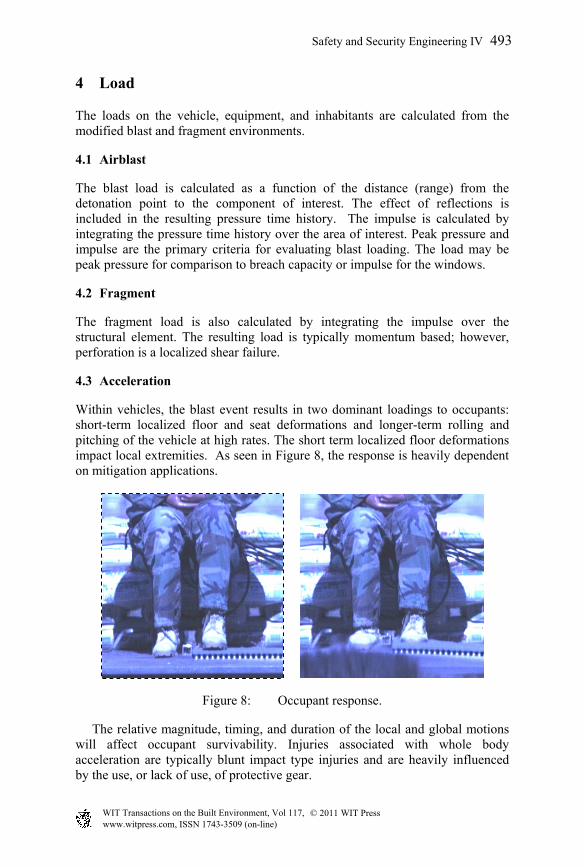
Within vehicles, the blast event results in two dominant loadings to occupants: short-term localized floor and seat deformations and longer-term rolling and pitching of the vehicle at high rates. The short term localized floor deformations impact local extremities. As seen in Figure 8, the response is heavily dependent on mitigation applications.
Figure 8: Occupant response.
The relative magnitude, timing, and duration of the local and global motions will affect occupant survivability. Injuries associated with whole body acceleration are typically blunt impact type injuries and are heavily influenced by the use, or lack of use, of protective gear.
Safety and Security Engineering IV 493
www.witpress.com, ISSN 1743-3509 (on-line) WIT Transactions on the Built Environment, Vol 117, © 2011 WIT Press
5 Response
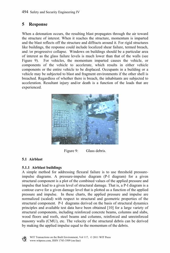
When a detonation occurs, the resulting blast propagates through the air toward the structure of interest. When it reaches the structure, momentum is imparted and the blast reflects off the structure and diffracts around it. For rigid structures like buildings, the response could include localized shear failure, termed breach, and /or progressive collapse. Windows on buildings should be a particular area of interest as the glass failure levels is much lower than that of the walls (see Figure 9). For vehicles, the momentum imparted causes the vehicle, or components of the vehicle to accelerate, which results in either vehicle components or the entire vehicle to be displaced. Occupants in a building or a vehicle may be subjected to blast and fragment environments if the other shell is breached. Regardless of whether there is breach, the inhabitants are subjected to acceleration. Resultant injury and/or death is a function of the loads that are experienced.
Figure 9: Glass debris.
5.1 Airblast
5.1.1 Airblast buildings A simple method for addressing flexural failure is to use threshold pressure-impulse diagrams. A pressure-impulse diagram (P-I diagram) for a given structural component is a plot of the combined values of the applied pressure and impulse that lead to a given level of structural damage. That is, a P-I diagram is a contour curve for a given damage level that is plotted as a function of the applied pressure and impulse. In these charts, the applied pressure and impulse are normalized (scaled) with respect to structural and geometric properties of the structural component. P-I diagrams derived on the basis of structural dynamics principles and available test data have been obtained [10] for a large variety of structural components, including reinforced concrete beams, columns and slabs, wood floors and roofs, steel beams and columns, reinforced and unreinforced masonry walls (CMU), etc. The velocity of the structural debris can be derived by making the applied impulse equal to the momentum of the debris.
494 Safety and Security Engineering IV
www.witpress.com, ISSN 1743-3509 (on-line) WIT Transactions on the Built Environment, Vol 117, © 2011 WIT Press
There are two simple methods for modeling a progressive collapse. One is the load transmission approach. In this method, the gravity loads are determined by “trickling” the weight of each unfailed component down a tree of supports and component failures are determined by comparing loads against capacities. In the matrix methodology, gravity loads are determined by assembling and solving a global stiffness problem (similar to a finite element method) and component failures are determined by comparing loads in each of the assumed response modes to capacities. If the structural components or associated connections fail, the mass distribution in the structure changes. It is generally assumed in the collapse methodologies that failed components and any equipment supported by them fall onto the components below them. The component on which they fall has an additional load to support.
5.1.2 Airblast – vehicles Response of the vehicle itself can be a localized failure of the various structural elements, translational movement, and/or overturning.
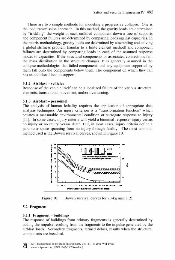
5.1.3 Airblast – personnel The analysis of human lethality requires the application of appropriate data analysis techniques. An injury criterion is a “transformation function” which equates a measurable environmental condition or surrogate response to injury [11]. In some cases, injury criteria will yield a binomial response: injury versus no injury or no injury versus death. But, in most cases, injury criteria define a parameter space spanning from no injury through fatality. The most common method used is the Bowen survival curves, shown in Figure 10.
Figure 10: Bowen survival curves for 70-kg man [12].
5.2 Fragment
5.2.1 Fragment – buildings The response of buildings from primary fragments is generally determined by adding the impulse resulting from the fragments to the impulse generated by the airblast loads. Secondary fragments, termed debris, results when the structural components are breached.
Safety and Security Engineering IV 495
www.witpress.com, ISSN 1743-3509 (on-line) WIT Transactions on the Built Environment, Vol 117, © 2011 WIT Press
5.2.2 Fragment – vehicles The response of vehicles subjected to fragments is determined in the same manner as for buildings.
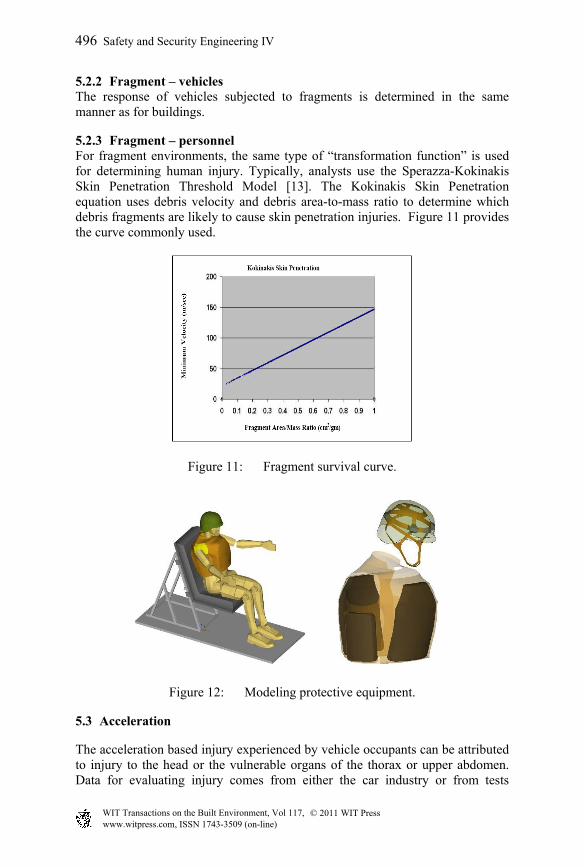
5.2.3 Fragment – personnel For fragment environments, the same type of “transformation function” is used for determining human injury. Typically, analysts use the Sperazza-Kokinakis Skin Penetration Threshold Model [13]. The Kokinakis Skin Penetration equation uses debris velocity and debris area-to-mass ratio to determine which debris fragments are likely to cause skin penetration injuries. Figure 11 provides the curve commonly used.
Figure 11: Fragment survival curve.
Figure 12: Modeling protective equipment.
5.3 Acceleration
The acceleration based injury experienced by vehicle occupants can be attributed to injury to the head or the vulnerable organs of the thorax or upper abdomen. Data for evaluating injury comes from either the car industry or from tests
496 Safety and Security Engineering IV
www.witpress.com, ISSN 1743-3509 (on-line) WIT Transactions on the Built Environment, Vol 117, © 2011 WIT Press
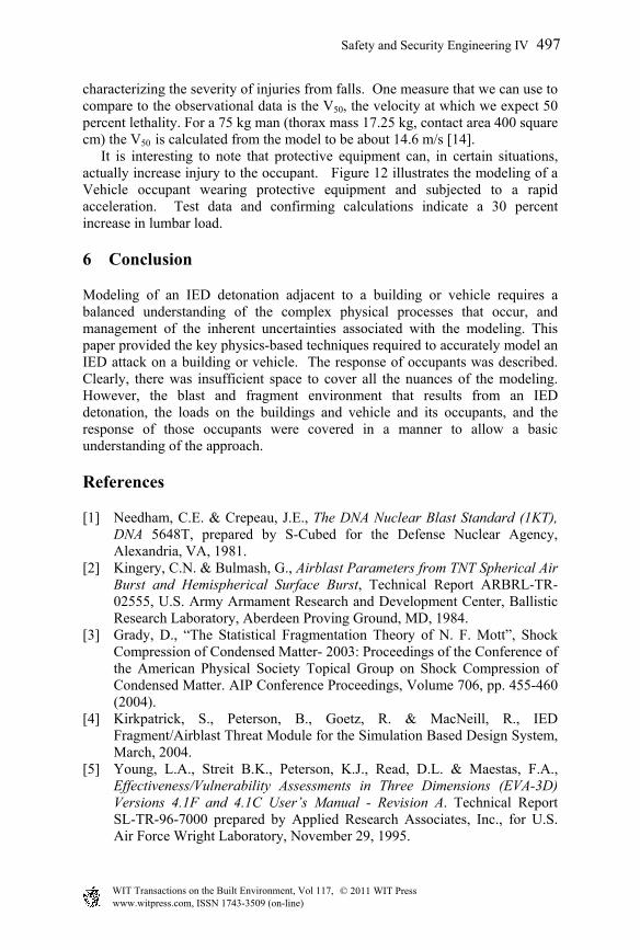
characterizing the severity of injuries from falls. One measure that we can use to compare to the observational data is the V50, the velocity at which we expect 50 percent lethality. For a 75 kg man (thorax mass 17.25 kg, contact area 400 square cm) the V50 is calculated from the model to be about 14.6 m/s [14]. It is interesting to note that protective equipment can, in certain situations, actually increase injury to the occupant. Figure 12 illustrates the modeling of a Vehicle occupant wearing protective equipment and subjected to a rapid acceleration. Test data and confirming calculations indicate a 30 percent increase in lumbar load.
6 Conclusion
Modeling of an IED detonation adjacent to a building or vehicle requires a balanced understanding of the complex physical processes that occur, and management of the inherent uncertainties associated with the modeling. This paper provided the key physics-based techniques required to accurately model an IED attack on a building or vehicle. The response of occupants was described. Clearly, there was insufficient space to cover all the nuances of the modeling. However, the blast and fragment environment that results from an IED detonation, the loads on the buildings and vehicle and its occupants, and the response of those occupants were covered in a manner to allow a basic understanding of the approach.
References
[1] Needham, C.E. & Crepeau, J.E., The DNA Nuclear Blast Standard (1KT), DNA 5648T, prepared by S-Cubed for the Defense Nuclear Agency, Alexandria, VA, 1981.
[2] Kingery, C.N. & Bulmash, G., Airblast Parameters from TNT Spherical Air Burst and Hemispherical Surface Burst, Technical Report ARBRL-TR-02555, U.S. Army Armament Research and Development Center, Ballistic Research Laboratory, Aberdeen Proving Ground, MD, 1984.
[3] Grady, D., “The Statistical Fragmentation Theory of N. F. Mott”, Shock Compression of Condensed Matter- 2003: Proceedings of the Conference of the American Physical Society Topical Group on Shock Compression of Condensed Matter. AIP Conference Proceedings, Volume 706, pp. 455-460 (2004).
[4] Kirkpatrick, S., Peterson, B., Goetz, R. & MacNeill, R., IED Fragment/Airblast Threat Module for the Simulation Based Design System, March, 2004.
[5] Young, L.A., Streit B.K., Peterson, K.J., Read, D.L. & Maestas, F.A., Effectiveness/Vulnerability Assessments in Three Dimensions (EVA-3D) Versions 4.1F and 4.1C User’s Manual - Revision A. Technical Report SL-TR-96-7000 prepared by Applied Research Associates, Inc., for U.S. Air Force Wright Laboratory, November 29, 1995.
Safety and Security Engineering IV 497
www.witpress.com, ISSN 1743-3509 (on-line) WIT Transactions on the Built Environment, Vol 117, © 2011 WIT Press
[6] Butler, L.A., Edwards, E.W., BRL-CAD Tutorial Series: Volume 1 – Overview and Installation, ARL-SR-113, U.S. Army Research Laboratory, February, 2002.
[7] Yatteau, J.D., Zernow, R.H. & Recht, R.F., FATEPEN2 Compact Fragment Penetration Model Volume 1 – Model Description, Report No. 5599-2, Applied Research Associates, Inc., January 1991.
[8] Bingham, B.L., Doolittle, C.M., Hacker, W.L., Hikida, S., Plamondon, M.A. & Whitehouse, S.R., A Code for Blast Effectiveness Against Mobile Systems (BEAMS Version 6.9), Theoretical Manual, prepared by Applied Research Associates, Inc. for U.S. Army Research Laboratory, December 2002.
[9] LS-DYNA Keyword User’s Manual, Livermore Software Technology Corporation, Version 970, April 2003.
[10] Facility and Component Explosive Damage Assessment Program (FACEDAP), Theory Manual, Version 1.2, Contract No. DACA 45-91-D-0019, U.S. Army Corps Engineers, Omaha, NE, May 1984.
[11] Young, L.A., Champion H.R. & Bass C.R., Bioengineering of Blast Injury, prepared for Combating Terrorism Technology Support Office, under Contract F08637-03-C-6006, April 2006.
[12] Bowen I.G., Fletcher E.R. & Richmond D.R., Estimate of Man’s Tolerance to the Direct Effects of Airblast, prepared by Lovelace Foundation for Medical Education and Research for the Defense Atomic Support Agency, DASA-2113, October 1968.
[13] Kokinakis, W. & Sperrazza, J., Criteria for Incapacitating Soldiers with Fragments and Flechettes, BRL Report No. 1269, Ballistic Research Laboratories, January 1965.
[14] Sturdivan, L.M., Human Vulnerability Modelling for Terrorist Bombing Risk Assessment, Army Research Laboratory Survivability and Lethality Analysis Directorate, December 2002.
498 Safety and Security Engineering IV
www.witpress.com, ISSN 1743-3509 (on-line) WIT Transactions on the Built Environment, Vol 117, © 2011 WIT Press

![Ullrich NDIA Munitions 021203 [Read-Only] · BLU-118B Thermobaric Bomb 90-day transition! 11 Defeat of Highly Mobile or Relocatable Targets Hellfire Thermobaric Blast/Frag Warhead](https://img.pdfslide.us/doc/110x75/5b6166e67f8b9a31488c6e8e/ullrich-ndia-munitions-021203-read-only-blu-118b-thermobaric-bomb-90-day-transition.jpg)