Embed Size (px)
Citation preview

EZ Trak Installation and Operations Manual
Unitec
www.StartwithUnitec.com

E Z T R A K
Document Number: EZT1001 ii Document Title: EZ Trak Installation and Operations Manual
EZ TRAK INSTALLATION AND
OPERATIONS MANUAL
This manual provides comprehensive installation, setup, and operational procedures for the EZ Trak Fleet Terminal.
If further assistance is needed, please contact the distributor from which the product was purchased.
When calling for assistance, you must have the following information available:
EZ Trak Serial Number:
Distributor Name: C O P Y R I G H T
© 2011 Unitec, Incorporated. All rights reserved. No part of this book, including text, screen examples, diagrams, or icons, may be reproduced or transmitted in any form, by any means (electronic, photocopying, recording, or otherwise) without prior written permission of Unitec, Incorporated.
T R A D E M A R K S
EZ Trak, Unitec, and the Unitec Logo are trademarks, service marks, or registered trademarks of Unitec, Incorporated.
E Z T R A K
Document Number: EZT1001 iii Document Title: EZ Trak Installation and Operations Manual
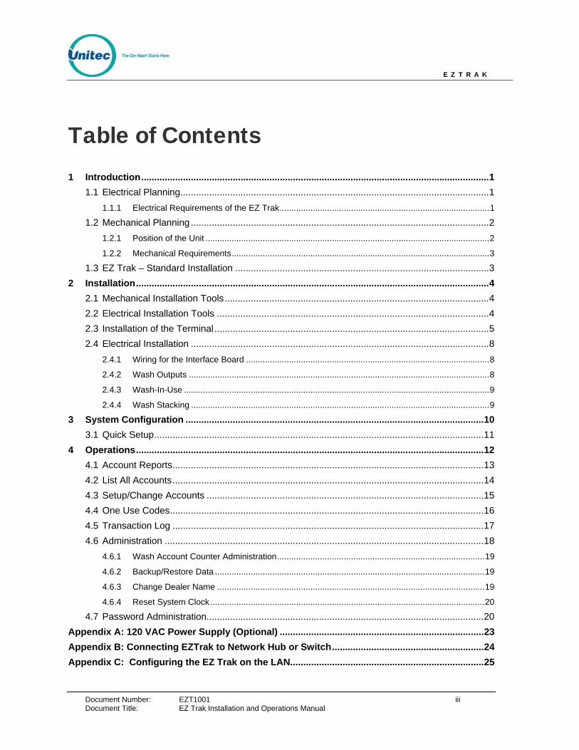
Table of Contents 1 Introduction.....................................................................................................................................1
1.1 Electrical Planning......................................................................................................................1 1.1.1 Electrical Requirements of the EZ Trak........................................................................................1
1.2 Mechanical Planning ..................................................................................................................2 1.2.1 Position of the Unit .......................................................................................................................2 1.2.2 Mechanical Requirements............................................................................................................3
1.3 EZ Trak – Standard Installation .................................................................................................3 2 Installation.......................................................................................................................................4
2.1 Mechanical Installation Tools.....................................................................................................4 2.2 Electrical Installation Tools ........................................................................................................4 2.3 Installation of the Terminal.........................................................................................................5 2.4 Electrical Installation ..................................................................................................................8
2.4.1 Wiring for the Interface Board ......................................................................................................8 2.4.2 Wash Outputs ..............................................................................................................................8 2.4.3 Wash-In-Use ................................................................................................................................9 2.4.4 Wash Stacking .............................................................................................................................9
3 System Configuration ..................................................................................................................10 3.1 Quick Setup..............................................................................................................................11
4 Operations.....................................................................................................................................12 4.1 Account Reports.......................................................................................................................13 4.2 List All Accounts.......................................................................................................................14 4.3 Setup/Change Accounts ..........................................................................................................15 4.4 One Use Codes........................................................................................................................16 4.5 Transaction Log .......................................................................................................................17 4.6 Administration ..........................................................................................................................18
4.6.1 Wash Account Counter Administration.......................................................................................19 4.6.2 Backup/Restore Data .................................................................................................................19 4.6.3 Change Dealer Name ................................................................................................................19 4.6.4 Reset System Clock...................................................................................................................20
4.7 Password Administration..........................................................................................................20 Appendix A: 120 VAC Power Supply (Optional) ..............................................................................23 Appendix B: Connecting EZTrak to Network Hub or Switch..........................................................24 Appendix C: Configuring the EZ Trak on the LAN..........................................................................25
E Z T R A K
Document Number: EZT1001 iv Document Title: EZ Trak Installation and Operations Manual
Index of Figures Figure 1. Conduits with Ethernet Cable Layout ............................................................................... 2 Figure 2. EZ Trak Base Placement.................................................................................................. 3 Figure 3. EZ Trak Terminal Base..................................................................................................... 5 Figure 4. EZ Trak Terminal Base Dimensions................................................................................. 6 Figure 5. Setting Anchor Bolts ......................................................................................................... 6 Figure 6. Interface Board Connections ............................................................................................ 8 Figure 7. Sample Account Report Screen ..................................................................................... 13 Figure 8. Sample List All Accounts Screen.................................................................................... 14 Figure 9. Setup/Change Account Screen ...................................................................................... 15 Figure 10. Sample One Use Codes Screen.................................................................................. 16 Figure 11. Sample Transaction Log Screen .................................................................................. 17 Figure 12. Administration Screen................................................................................................... 18 Figure 13. Password Administration Screen.................................................................................. 20
Index of Tables Table 1. Wash Program Relays ....................................................................................................... 9 Table 2. Wash-In-Use Signal ........................................................................................................... 9

E Z T R A K
Document Number: EZT1001 1 Document Title: EZ Trak Installation and Operations Manual
1 Introduction The EZ Trak fleet terminal is a drive-up entry system developed specifically for the automobile dealer market. EZ Trak cards and codes allow the dealer to track all wash use by driver and department. EZ Trak can be used to track car wash use by rental companies, neighboring dealerships and businesses.
EZ Trak is designed to integrate with the dealer’s local computer network. It requires 24 Volt AC or DC power, Intranet (Ethernet) connection, and a web browser.
1.1 Electrical Planning
1.1.1 Electrical Requirements of the EZ Trak
The EZ Trak requires 24 VAC 1-amp service, which should be provided during wash construction. Most installers will have power supplied directly from one of the three phases used to power the wash motors and controllers. If this method is used, special attention should be given to proper earth grounding at the unit, as well as in the breaker panel.
Make sure that the protective earth ground wire does not carry any motor return current. Only the neutral wire should carry return current.
The EZ Trak activates one wash type. The car wash’s Programmable Logic Controller (PLC) activation voltage is routed to the EZ Trak interface board and back to the car wash controller. In addition, a Wash-In-Use Hot and Wash-In-Use Neutral are required to properly activate the EZ Trak operator interface and maintain accurate accounting information. Typically, these are also provided by the PLC. It is important to consider this fact when planning the conduit runs, because there will need to be 2 separate runs from the wash to the EZ Trak—one for AC power, and one for PLC Control Wires and the Ethernet cable. The base of the EZ Trak terminal provides two knock-outs as well as the hole in the units' base to accommodate various conduit installation options.
An Ethernet cable is required to program the EZ Trak. This cable should be standard CAT 5 or CAT 6. This cable can be pulled with the control wires. The cable is connected to the Dealer’s Ethernet switch or router.

E Z T R A K
Document Number: EZT1001 2
Figure 1. Conduits with Ethernet Cable Layout
Important: DO NOT RUN CABLE OUTSIDE OF A CONDUIT!
Follow all local and National Electric Codes.
Finally, it should be understood that the EZ Trak terminal is to be powered by wires of at least 18 AWG, or larger. Failure to adhere to this recommendation could result in a fire or injury. When installing the conduit, it is suggested that it be a minimum of ¾” in size, and be made of metal versus PVC.
1.2 Mechanical Planning
1.2.1 Position of the Unit
The proper positioning of the EZ Trak terminal is very important. Figure 2 of this section should be used as a reference for good layout practices. There are several layout considerations that follow, which may be a good idea to think about.
The EZ Trak terminal should be placed 10-14 feet from the car wash entrance to ensure the proper timing and flow of customers. The wash’s treadle switch should be centered along the horizontal plane, approximately 18” inches out from the front of the EZ Trak terminal. This will ensure that the car/truck’s wheel is aligned with the treadle switch, as shown in Figure 2. Finally, a concrete post can be positioned just to the front and left corner of the unit, to act as a protective buffer. A typical size for this post is between 30 and 35 inches.
Document Title: EZ Trak Installation and Operations Manual
E Z T R A K
Document Number: EZT1001 3
1.2.2 Mechanical Requirements
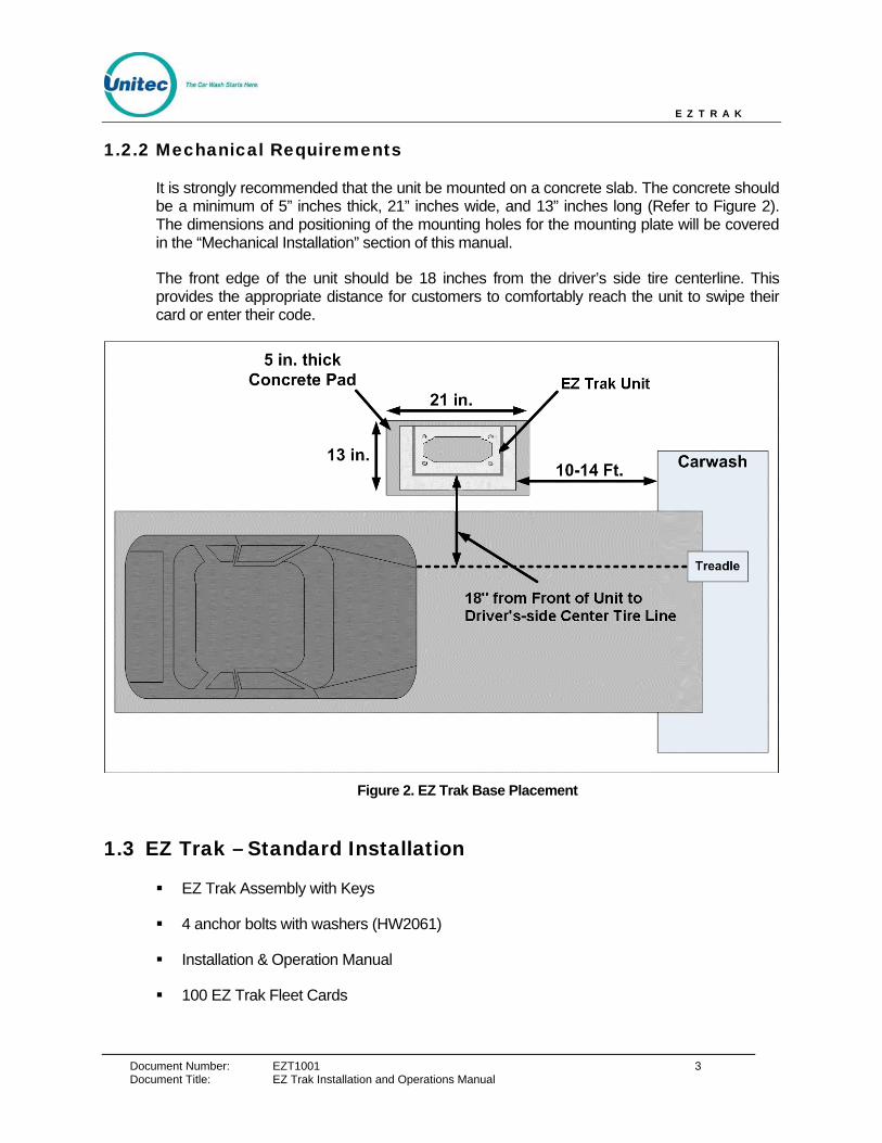
It is strongly recommended that the unit be mounted on a concrete slab. The concrete should be a minimum of 5” inches thick, 21” inches wide, and 13” inches long (Refer to Figure 2). The dimensions and positioning of the mounting holes for the mounting plate will be covered in the “Mechanical Installation” section of this manual.
The front edge of the unit should be 18 inches from the driver’s side tire centerline. This provides the appropriate distance for customers to comfortably reach the unit to swipe their card or enter their code.
Figure 2. EZ Trak Base Placement
1.3 EZ Trak – Standard Installation
EZ Trak Assembly with Keys
4 anchor bolts with washers (HW2061)
Installation & Operation Manual
100 EZ Trak Fleet Cards
Document Title: EZ Trak Installation and Operations Manual

E Z T R A K
Document Number: EZT1001 4 Document Title: EZ Trak Installation Manual
2 Installation
2.1 Mechanical Installation Tools
The following tools are recommended for the typical mechanical installation of this EZ Trak unit:
6” inch or longer ratchet extension (for optional straight base)
¾” inch deep well socket and socket wrench
Small, thin blade, flat-tip screwdriver
Hammer drill
½” Concrete hammer drill bit
Hammer
Dual-plane Level
50’ foot tape measure
2.2 Electrical Installation Tools
Small, thin tipped, straight screwdriver (1/8” tip, for green Phoenix connectors)
Wire strippers (capable of handling 10-22 AWG wire)
Cable or wire tie wraps
Diagonal cutters
Needle nose pliers
5/16” nut-driver
¼” nut-driver
Phillips-head and flat-head screwdrivers

E Z T R A K
Document Number: EZT1001 5
2.3 Installation of the Terminal
The EZ Trak terminal is bolted onto the concrete base. Perform the following steps:
1. Center the EZ Trak terminal on the concrete base. Please note that the bolt holes are inside the terminal, as shown in the picture the below.
Figure 3. EZ Trak Terminal Base
2. Mark the 4 holes that you intend to drill in order to mount the EZ Trak. Mark the holes with a marker as the terminal is sitting on top of the concrete. It is important to keep in mind that the conduit run will need to protrude through the cutout in the base by at least 3 inches.
Document Title: EZ Trak Installation and Operations Manual
E Z T R A K
Document Number: EZT1001 6
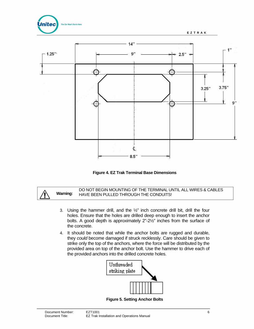
Figure 4. EZ Trak Terminal Base Dimensions
Warning: DO NOT BEGIN MOUNTING OF THE TERMINAL UNTIL ALL WIRES & CABLES HAVE BEEN PULLED THROUGH THE CONDUITS!
3. Using the hammer drill, and the ½” inch concrete drill bit, drill the four
holes. Ensure that the holes are drilled deep enough to insert the anchor bolts. A good depth is approximately 2”-2½” inches from the surface of the concrete.
4. It should be noted that while the anchor bolts are rugged and durable, they could become damaged if struck recklessly. Care should be given to strike only the top of the anchors, where the force will be distributed by the provided area on top of the anchor bolt. Use the hammer to drive each of the provided anchors into the drilled concrete holes.
Figure 5. Setting Anchor Bolts
Document Title: EZ Trak Installation and Operations Manual

E Z T R A K
Document Number: EZT1001 7 Document Title: EZ Trak Installation and Operations Manual
5. When all anchor bolts have been set, place one nut onto each of them, and use the ratchet and socket to tighten it, until as many of the threads from the bolts as possible are showing. There should also be sufficient threads on the anchor bolts left to secure the plate in place with the remaining 4 nuts. If this is not the case, the holes in the concrete were drilled too deep, and the installer should use smaller, or no leveling nuts.
6. Securely fasten the 4 nuts with the socket wrench. When this has been successfully completed, there should be no movement in the EZ Trak whatsoever.
NOTE: It is very important to allow at least 66” inches of wire to remain draped over the top of the conduit, so that there is enough left to make all of the electrical connections. It is also recommended that 3” or more of conduit protrude the bottom of the terminal. This is to ensure that standing water will not accumulate in the conduit.
E Z T R A K
Document Number: EZT1001 8
2.4 Electrical Installation
2.4.1 Wiring for the Interface Board
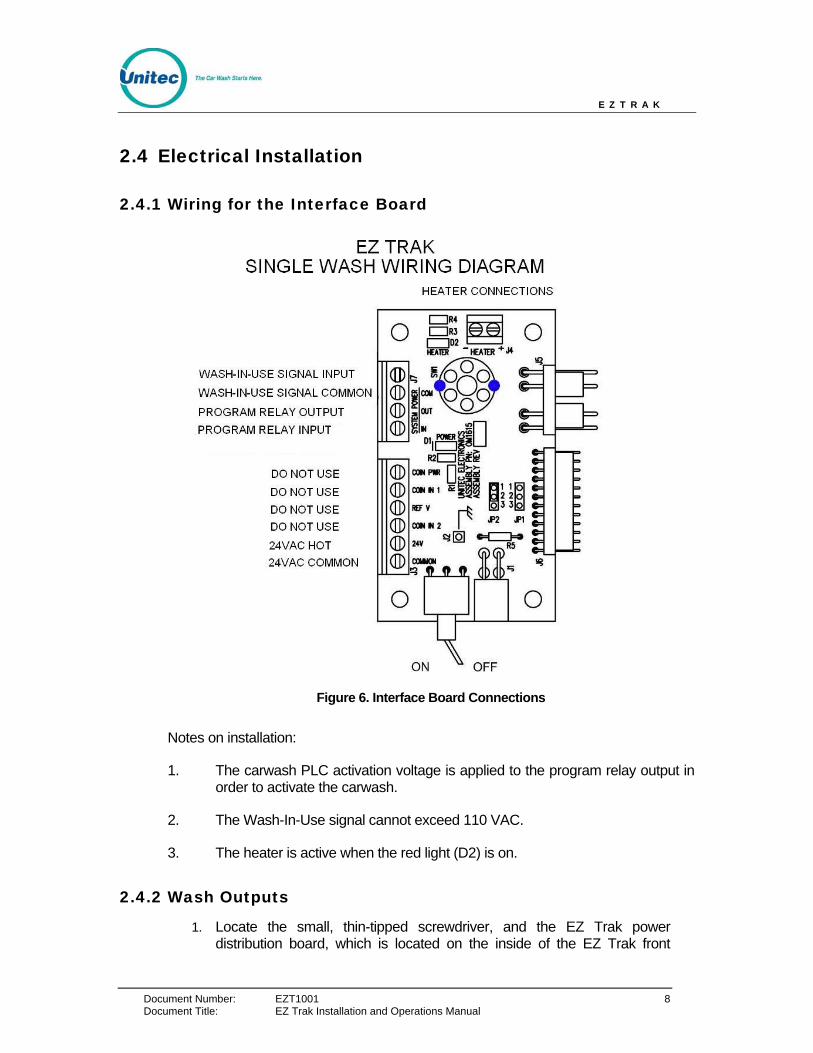
Figure 6. Interface Board Connections
Notes on installation:
1. The carwash PLC activation voltage is applied to the program relay output in order to activate the carwash.
2. The Wash-In-Use signal cannot exceed 110 VAC.
3. The heater is active when the red light (D2) is on.
2.4.2 Wash Outputs
1. Locate the small, thin-tipped screwdriver, and the EZ Trak power distribution board, which is located on the inside of the EZ Trak front
Document Title: EZ Trak Installation and Operations Manual
E Z T R A K
Document Number: EZT1001 9 Document Title: EZ Trak Installation and Operations Manual
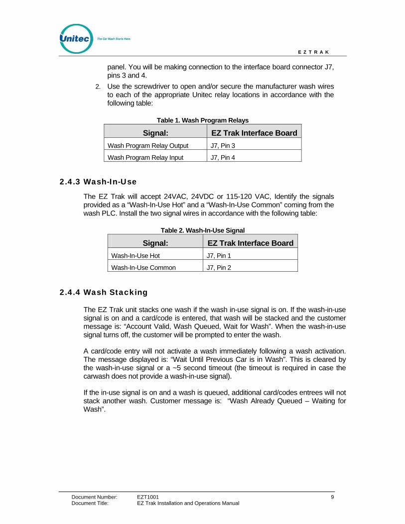
panel. You will be making connection to the interface board connector J7, pins 3 and 4.
2. Use the screwdriver to open and/or secure the manufacturer wash wires to each of the appropriate Unitec relay locations in accordance with the following table:
Table 1. Wash Program Relays
Signal: EZ Trak Interface Board Wash Program Relay Output J7, Pin 3
Wash Program Relay Input J7, Pin 4
2.4.3 Wash-In-Use
The EZ Trak will accept 24VAC, 24VDC or 115-120 VAC, Identify the signals provided as a “Wash-In-Use Hot” and a “Wash-In-Use Common” coming from the wash PLC. Install the two signal wires in accordance with the following table:
Table 2. Wash-In-Use Signal
Signal: EZ Trak Interface Board Wash-In-Use Hot J7, Pin 1
Wash-In-Use Common J7, Pin 2
2.4.4 Wash Stacking
The EZ Trak unit stacks one wash if the wash in-use signal is on. If the wash-in-use signal is on and a card/code is entered, that wash will be stacked and the customer message is: “Account Valid, Wash Queued, Wait for Wash”. When the wash-in-use signal turns off, the customer will be prompted to enter the wash.
A card/code entry will not activate a wash immediately following a wash activation. The message displayed is: “Wait Until Previous Car is in Wash”. This is cleared by the wash-in-use signal or a ~5 second timeout (the timeout is required in case the carwash does not provide a wash-in-use signal).
If the in-use signal is on and a wash is queued, additional card/codes entrees will not stack another wash. Customer message is: “Wash Already Queued – Waiting for Wash”.
E Z T R A K
Document Number: EZT1001 10 Document Title: EZ Trak Installation and Operations Manual
3 System Configuration Setup and configuration of the EZ Trak is completed via the Internet using a laptop or desktop computer with Internet access. The network parameters for the EZ Trak terminal are configured at the terminal itself.
The Fleet Terminal Ethernet interface comes shipped pre-configured with the following settings:
• IP Address: 192.168.0.108
• Netmask: 255.255.255.0
• Gateway: 192.168.0.1
• DHCP: Off
To confirm these settings, enter the keypad code “123456789#”. The current: IP address, Netmask, Gateway, MAC address, DHCP mode, DHCP Fallback mode and Fallback IP address are displayed. Press the “#” key to return to operational mode.
If any of the preconfigured information conflicts with your router or network settings, you will need to change the network parameters at the EZ Trak terminal. To leave a parameter unchanged, press the “#” key to skip past that parameter. There is no backspace key. Therefore, if you make a mistake you need to cycle through the menu again and make the correct entry.
Note: This function does NOT time-out return to operational mode by default. You MUST press the “#” key until the unit cycles back in to operational mode.
To change a parameter, perform the following steps:
1. Cycle the power on the EZ Trak. Upon boot up, enter the keypad code “1397#” during the first 20 seconds.
2. Press “1#” to turn DHCP on or press “0#” to turn DHCP off. The default setting for DHCP is off.
3. Enter the IP address. Use the “*” key as a “.”. The current value is displayed.
4. Enter the Gateway address. Use the “*” key as a “.”. The current value is displayed.
5. Enter the Nameserver (Netmask) address. Use the “*” key as a “.”. The current value is displayed.
6. All network parameters will then be displayed. Press the # key to exit.

E Z T R A K
Document Number: EZT1001 11 Document Title: EZ Trak Installation and Operations Manual
3.1 Quick Setup
To access the EZ Trak main menu, connect the Ethernet port to you PC network hub or router then enter http://192.168.0.108 (or the IP address you programmed) into your web browser address.
1. Login to the Main Menu using the Master login User Name: NADA and Password: UE.
2. Login to the Password Administration Menu using the Master login. Enter all screen user names and passwords. Check the box and click Submit.
3. Login to the Admin Menu. Enter the current date and time, check Set Current Time then click Submit. Select all boxes under Reset System Counters then click Submit. Return to the Main Menu.
4. Login to the One Use Codes Menu. Select Generate New One-Time-Use Codes then click Submit. Print the One Use Codes page (using computer print commands) for reference. Select Clear All One-Time-Use Codes but keep the sheet for setting up pin numbers. Return to the Main Menu.
5. Login to the Account Setup-Change menu. Select the number of accounts you would like to add. Enter the Account name. Enter the Department. Enter the number of Remaining Washes. Enter the card and/or keypad codes. Select the Key/Card Status from the drop-down menu. Click Submit.
The EZ Trak system is now ready to operate. Test the accounts you entered by swiping a programmed card or entering a code. Be sure the wash is fired.
E Z T R A K
Document Number: EZT1001 12 Document Title: EZ Trak Installation and Operations Manual
4 Operations The EZ Track Fleet Terminal main menu includes the following functions, as defined below:
• Account Reports – provides a detailed report of account usage for every account or a summary of usage for each department.
• List All Accounts – provides a detailed list of all accounts plus a link to setup accounts.
• Setup Change Accounts – used to add and deleted up to 100 accounts, set the account name and department, set the account numeric code or VIP Wash card code, and set the type of code activation: keypad, card, either, or both. You can also disable an account with the option. Accounts are displayed in groups of 10.
• One Use Codes -- provides 50 keypad codes that will activate the wash once. These codes are valid until used or until a new set of codes is generated. When entering a keypad code at the terminal, the code is followed by the “#” key which acts as the “enter” key.
• Transaction Log – provides a detailed list of the last 100 transactions at the Fleet Terminal.
• Administration – used to reset accounting counters, backup and restore data, change the carwash name, and set the current time in the Fleet Terminal.
• Password Administration – prevents unauthorized login of the EZ Trak system by assigning a User Name and Password to each screen.
E Z T R A K
Document Number: EZT1001 13
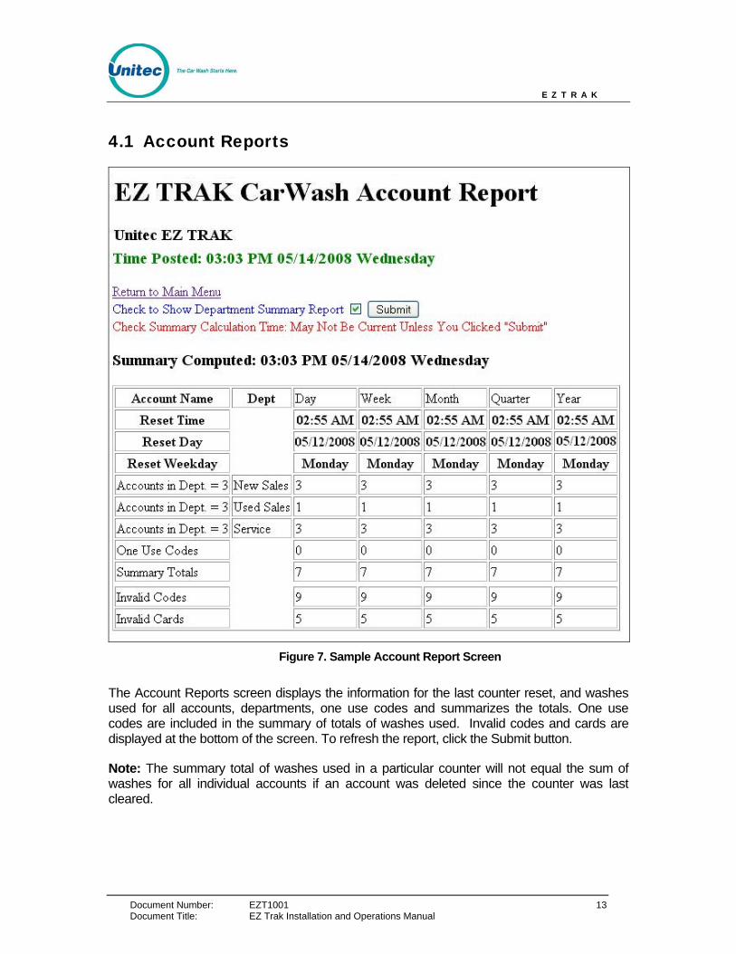
4.1 Account Reports
Figure 7. Sample Account Report Screen
The Account Reports screen displays the information for the last counter reset, and washes used for all accounts, departments, one use codes and summarizes the totals. One use codes are included in the summary of totals of washes used. Invalid codes and cards are displayed at the bottom of the screen. To refresh the report, click the Submit button.
Note: The summary total of washes used in a particular counter will not equal the sum of washes for all individual accounts if an account was deleted since the counter was last cleared.
Document Title: EZ Trak Installation and Operations Manual
E Z T R A K
Document Number: EZT1001 14
4.2 List All Accounts
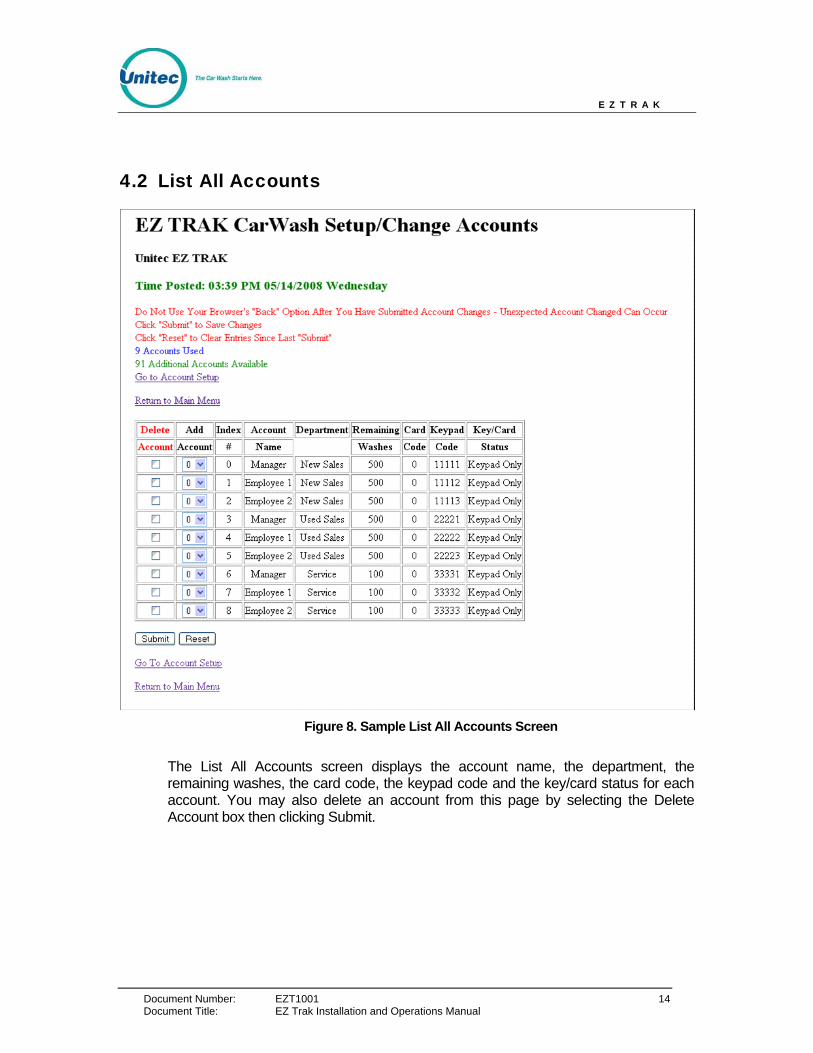
Figure 8. Sample List All Accounts Screen
The List All Accounts screen displays the account name, the department, the remaining washes, the card code, the keypad code and the key/card status for each account. You may also delete an account from this page by selecting the Delete Account box then clicking Submit.
Document Title: EZ Trak Installation and Operations Manual
E Z T R A K
Document Number: EZT1001 15
4.3 Setup/Change Accounts
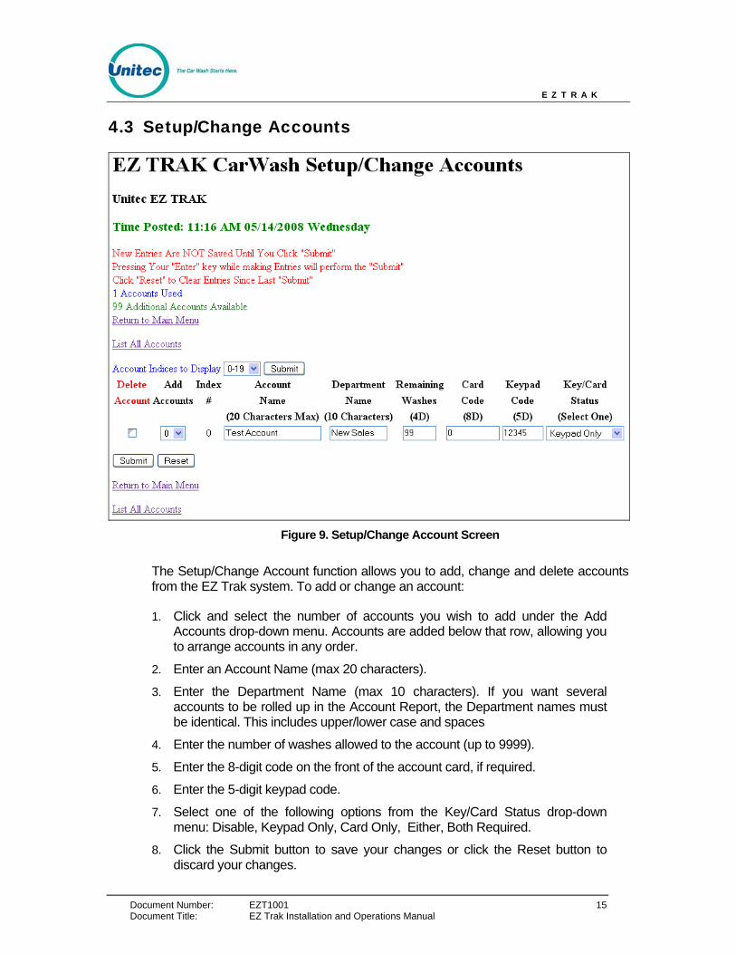
Figure 9. Setup/Change Account Screen
The Setup/Change Account function allows you to add, change and delete accounts from the EZ Trak system. To add or change an account:
1. Click and select the number of accounts you wish to add under the Add Accounts drop-down menu. Accounts are added below that row, allowing you to arrange accounts in any order.
2. Enter an Account Name (max 20 characters).
3. Enter the Department Name (max 10 characters). If you want several accounts to be rolled up in the Account Report, the Department names must be identical. This includes upper/lower case and spaces
4. Enter the number of washes allowed to the account (up to 9999).
5. Enter the 8-digit code on the front of the account card, if required.
6. Enter the 5-digit keypad code.
7. Select one of the following options from the Key/Card Status drop-down menu: Disable, Keypad Only, Card Only, Either, Both Required.
8. Click the Submit button to save your changes or click the Reset button to discard your changes.
Document Title: EZ Trak Installation and Operations Manual
E Z T R A K
Document Number: EZT1001 16
9. To delete an account, select the Delete Account box next to the account you wish to delete then click Submit.
4.4 One Use Codes
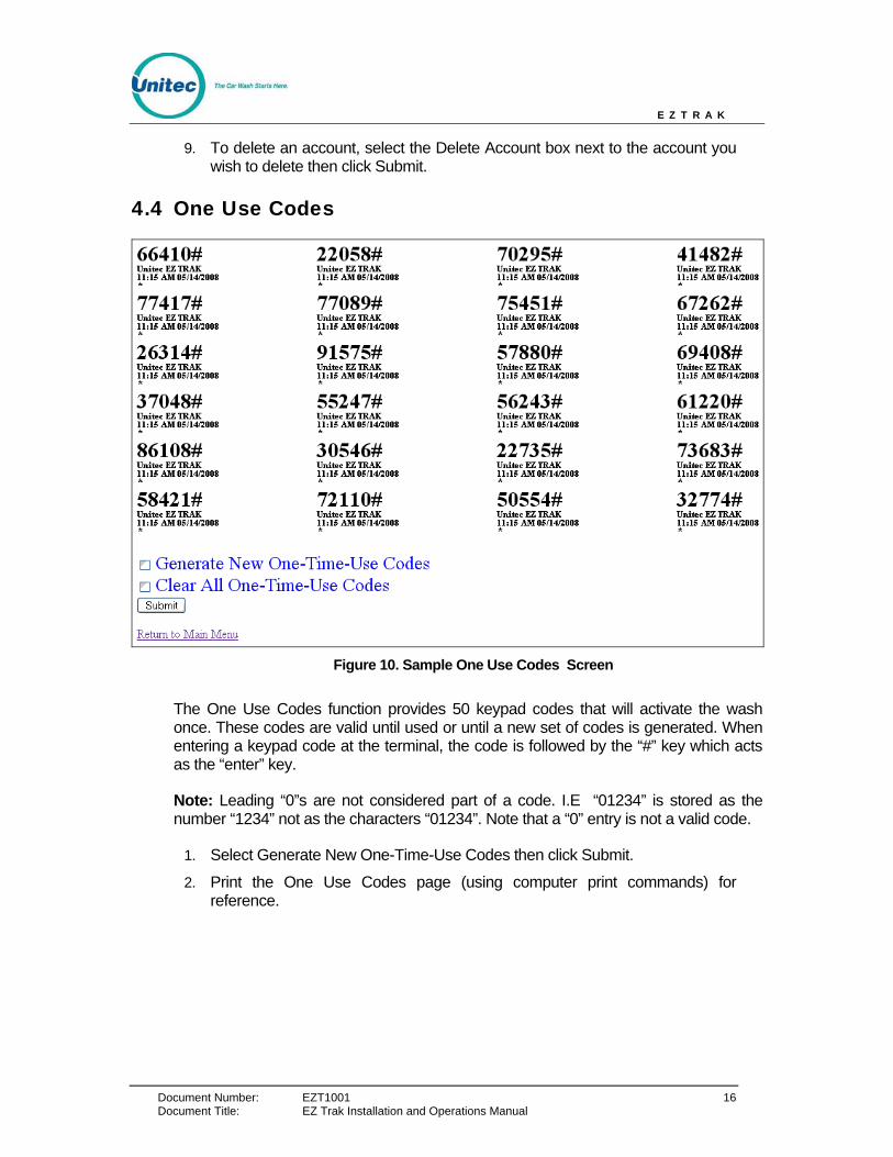
Figure 10. Sample One Use Codes Screen
The One Use Codes function provides 50 keypad codes that will activate the wash once. These codes are valid until used or until a new set of codes is generated. When entering a keypad code at the terminal, the code is followed by the “#” key which acts as the “enter” key.
Note: Leading “0”s are not considered part of a code. I.E “01234” is stored as the number “1234” not as the characters “01234”. Note that a “0” entry is not a valid code.
1. Select Generate New One-Time-Use Codes then click Submit.
2. Print the One Use Codes page (using computer print commands) for reference.
Document Title: EZ Trak Installation and Operations Manual
E Z T R A K
Document Number: EZT1001 17
4.5 Transaction Log
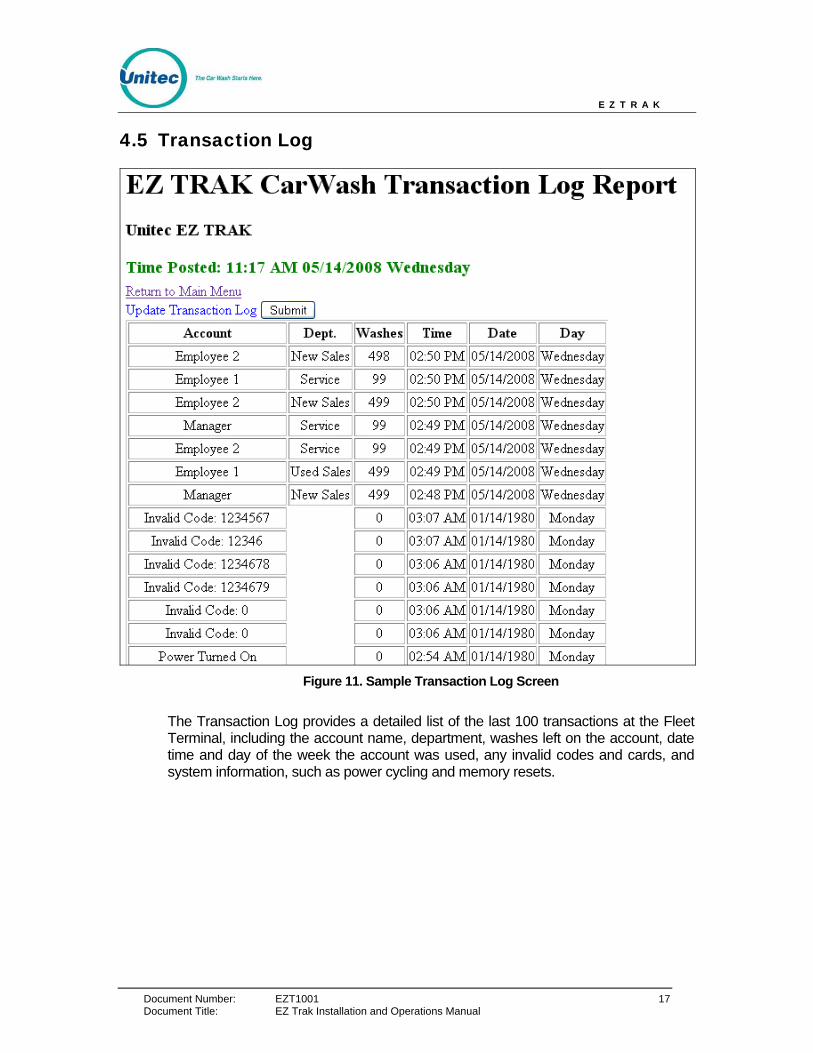
Figure 11. Sample Transaction Log Screen
The Transaction Log provides a detailed list of the last 100 transactions at the Fleet Terminal, including the account name, department, washes left on the account, date time and day of the week the account was used, any invalid codes and cards, and system information, such as power cycling and memory resets.
Document Title: EZ Trak Installation and Operations Manual
E Z T R A K
Document Number: EZT1001 18
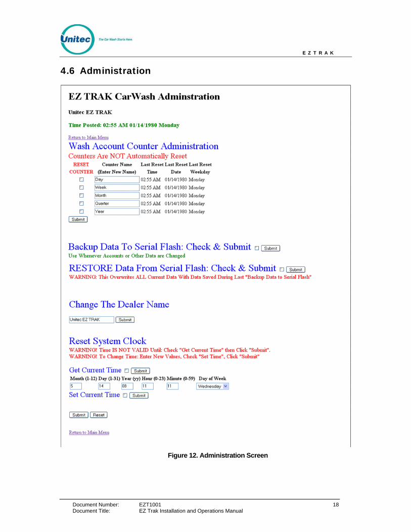
4.6 Administration
Figure 12. Administration Screen
Document Title: EZ Trak Installation and Operations Manual
E Z T R A K
Document Number: EZT1001 19 Document Title: EZ Trak Installation and Operations Manual
The Administration screen allows you to perform several administrative functions for the EZ Trak system, including resetting system counters, backing up and restoring data, changing the dealer name, and resetting the system clock.
4.6.1 Wash Account Counter Administration
The Wash Account Counter Administration function allows you to reset system counters by day, week month, quarter or year or any other increment you chose. You may rename any reset increment by typing a new name in the field and clicking Submit. To reset system counters, select the box by the system counter and click submit.
4.6.2 Backup/Restore Data
The “Backup” features saves all data normally held in memory to a serial flash. This data includes: account information, user names/passwords, account usage data, one use codes and the transaction log. You should backup your data at least every time you make changes to the accounts or passwords.
The “Restore” feature replaces all current data in memory with the data from the serial flash. Note that this restores all system information to the state it was in when the last “Backup” was done.
The Restore function also restores all of the user names/passwords and other information displayed on the administration web page. However, if you Restore data and then click and submit from the administration web page before leaving that page you will overwrite the restored data with the data on that page. For example, you can keep your current user names/passwords after a restore by checking and submitting the change passwords option immediately after the restore. If you do not click submit from the administration web page, the user names/passwords at the time of the last “backup” will be active.
Warning: All changes to the accounts, passwords, account usage, and transaction log since the last Backup are lost!!! If you have never done a “Backup” the restore function doesn’t work.
If memory fails in the unit when power is turned on (i.e. a dead battery), the unit will automatically restore memory from the serial flash if a backup was previously done. If no serial flash backup exists, all data in memory will be lost.
4.6.3 Change Dealer Name
You may customize the EZ Trak to display any dealer name you wish. Simply enter the new dealer name and click the Submit button.

E Z T R A K
Document Number: EZT1001 20
4.6.4 Reset System Clock
The Reset System Clock function allows you to set the local time on the EZ Trak system world-wide. Enter the date, time and day of the week and click the Submit button. The system time does not automatically update, so it will need to be manually updated for Daylight SavingsTime.
4.7 Password Administration
Figure 13. Password Administration Screen
The Password Administration screen allows you to manage access to the EZ Trak system. Passwords are required to access all web pages (except the main menu). Passwords provide access to one specific web page.
Once a web page is first accessed, a window will pop up and prompt for the user name and password. If a valid username/password is entered, the web page will be shown. Several attempts are given. If all attempts fail, a blank page will display. Once the page is accessed, you will not be required to reenter the username and password
Document Title: EZ Trak Installation and Operations Manual

E Z T R A K
Document Number: EZT1001 21 Document Title: EZ Trak Installation and Operations Manual
during that session. If you terminate the browser and restart, the user name/password will be required again.
A master username and password plus default usernames and passwords for each web page are provided in the system. You may change any or all of user names and passwords (max 15 characters each) on the Password Administration page. Once the values are changed, you must click Submit to save the changes.
If you forget the master password, swipe the “Reset Password” card at the EZ TRAK unit to return all passwords to the factory default.
Default values are as follows:
Master Username/Password: NADA/UE
Setup Account Username/Password: Setup/Setup
List Accounts Username/Password: List/List
One Use Codes Username/Password: Oneuse/Oneuse
Account Report Username/Password: Report/Report
Transaction Log Username/Password: Log/Log
Passwords Tips:
• The Master password provides access to all web pages and the administration pages.
• No user names should be the same.
• No user passwords should be the same.
• Blanks spaces should not be used in the users name or passwords.
• Blanks and duplicate names/passwords will be accepted but the names/passwords will not work.
• If a user name or password is blank, that password will not work. Only the master will then have access to that page.

E Z T R A K
Document Number: EZT1001 22 Document Title: EZ Trak Installation and Operations Manual
E Z T R A K
Document Number: EZT1001 23
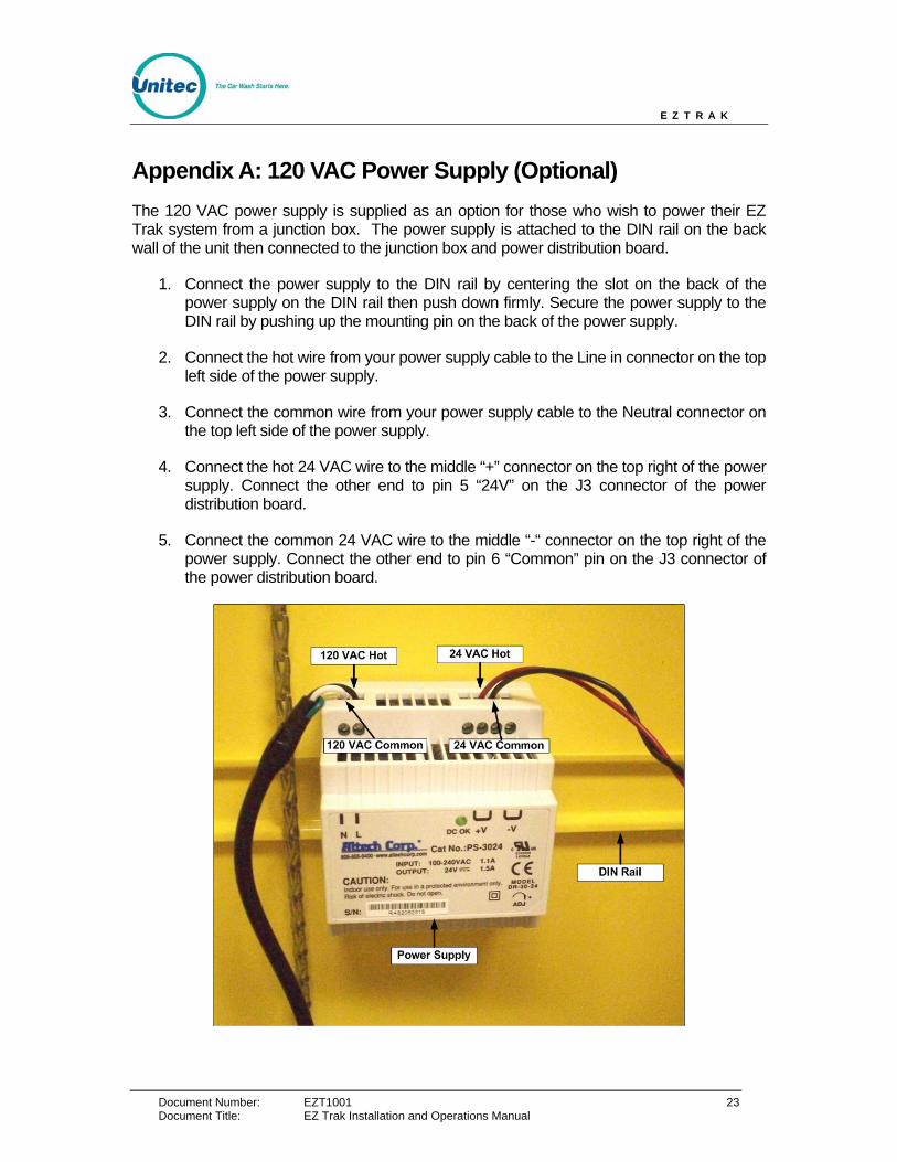
Appendix A: 120 VAC Power Supply (Optional) The 120 VAC power supply is supplied as an option for those who wish to power their EZ Trak system from a junction box. The power supply is attached to the DIN rail on the back wall of the unit then connected to the junction box and power distribution board.
1. Connect the power supply to the DIN rail by centering the slot on the back of the power supply on the DIN rail then push down firmly. Secure the power supply to the DIN rail by pushing up the mounting pin on the back of the power supply.
2. Connect the hot wire from your power supply cable to the Line in connector on the top left side of the power supply.
3. Connect the common wire from your power supply cable to the Neutral connector on the top left side of the power supply.
4. Connect the hot 24 VAC wire to the middle “+” connector on the top right of the power supply. Connect the other end to pin 5 “24V” on the J3 connector of the power distribution board.
5. Connect the common 24 VAC wire to the middle “-“ connector on the top right of the power supply. Connect the other end to pin 6 “Common” pin on the J3 connector of the power distribution board.
Document Title: EZ Trak Installation and Operations Manual

E Z T R A K
Document Number: EZT1001 24
Appendix B: Connecting EZTrak to Network Hub or Switch A standard Cat5 cable is used to connect the EZTrak to a network hub or switch using standard “straight-through” wiring in the connectors. A straight through cable has both ends with the same pin color code. These cables may be readily purchased from Radio Shack, but you may also wire the connector yourself. In this case, wire the connectors as follows:
RJ45 Jack and Plug Pin Location
RJ45 Pin # Wire Color (T568B)
Wire Diagram(T568B)
1 White/Orange 2 Orange 3 White/Green 4 Blue 5 White/Blue 6 Green 7 White/Brown 8 Brown
Straight-Through Cable Pinout for T568B
Document Title: EZ Trak Installation and Operations Manual
E Z T R A K
Document Number: EZT1001 25
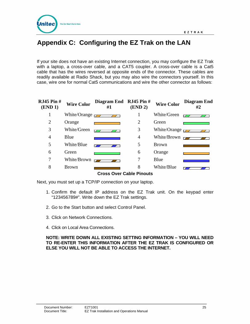
Appendix C: Configuring the EZ Trak on the LAN
If your site does not have an existing Internet connection, you may configure the EZ Trak with a laptop, a cross-over cable, and a CAT5 coupler. A cross-over cable is a Cat5 cable that has the wires reversed at opposite ends of the connector. These cables are readily available at Radio Shack, but you may also wire the connectors yourself. In this case, wire one for normal Cat5 communications and wire the other connector as follows:
RJ45 Pin # (END 1) Wire Color Diagram End
#1 RJ45 Pin #
(END 2) Wire Color Diagram End #2
1 White/Orange 1 White/Green 2 Orange 2 Green 3 White/Green 3 White/Orange 4 Blue 4 White/Brown 5 White/Blue 5 Brown 6 Green 6 Orange 7 White/Brown 7 Blue 8 Brown 8 White/Blue
Cross Over Cable Pinouts
Next, you must set up a TCP/IP connection on your laptop.
1. Confirm the default IP address on the EZ Trak unit. On the keypad enter “123456789#”. Write down the EZ Trak settings.
2. Go to the Start button and select Control Panel.
3. Click on Network Connections.
4. Click on Local Area Connections.
NOTE: WRITE DOWN ALL EXISTING SETTING INFORMATION – YOU WILL NEED TO RE-ENTER THIS INFORMATION AFTER THE EZ TRAK IS CONFIGURED OR ELSE YOU WILL NOT BE ABLE TO ACCESS THE INTERNET.
Document Title: EZ Trak Installation and Operations Manual
E Z T R A K
Document Number: EZT1001 26
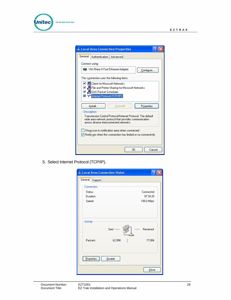
5. Select Internet Protocol (TCP/IP).
Document Title: EZ Trak Installation and Operations Manual
E Z T R A K
Document Number: EZT1001 27
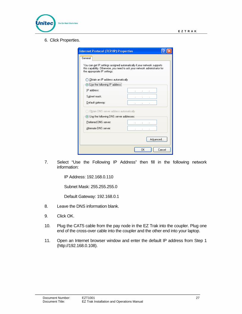
6. Click Properties.
7. Select “Use the Following IP Address” then fill in the following network information:
IP Address: 192.168.0.110
Subnet Mask: 255.255.255.0
Default Gateway: 192.168.0.1
8. Leave the DNS information blank.
9. Click OK.
10. Plug the CAT5 cable from the pay node in the EZ Trak into the coupler. Plug one end of the cross-over cable into the coupler and the other end into your laptop.
11. Open an Internet browser window and enter the default IP address from Step 1 (http://192.168.0.108).
Document Title: EZ Trak Installation and Operations Manual