Embed Size (px)
Citation preview

EZ Build Assembly and InstallationDP 5.0-6.8 Plow with E-58H 12V Hydraulic Unit
and41150 Drive Pro 6.8-7.6 Plow with E-58H 12V Hydraulic Unit
© 2012 Printed in the U.S.A.
Meyer Products LLC18513 Euclid Ave. • Cleveland, Ohio 44112-1084
Phone 216-486-1313www.meyerproducts.com• email [email protected]
Meyer Products LLC reserves the right, under its continuing product improvement program, to change construction or design details, specifications and prices without notice or without incurring any obligation.
Form No. 1-1050 March 2012

Table of Contents
General Information ............................................................................................................................................................................. 1Illustrated Parts Lists ..........................................................................................................................................................................2-4Attaching Plow to EZ Build Assembly ............................................................................................................................................. 5Vehicle Side Wiring Diagram.............................................................................................................................................................. 6Drop Speed Adjustment ..................................................................................................................................................................... 7Stop Bolt Adjustment ........................................................................................................................................................................... 7Mount Plow System To Vehicle ......................................................................................................................................................... 8Dis-Mount Plow System From Vehicle ............................................................................................................................................ 9Pre-Delivery Inspection ..................................................................................................................................................................... 10Accessories ..............................................................................................................................................................................................11
Web Based Support
(1)
GENERAL INFORMATION
Always disconnect battery prior to installation.
SAFETY PRECAUTIONS should be used when Quik Lift® is in a RAISED position.LOWER plow to the ground when vehicle is PARKED.
OVERHAUL and SERVICE information is covered on separate instructions.
Lift arm should be removed from vehicle if / when snowplow is removed.
Note:1. Connect ground cable to negative side of battery for a solid connection to ground.2. Route all cables away from moving engine parts, Manifolds, and sharp sheet metal.3. For weather protection, coat all connections with Meyer Dielectric Grease Part No. 156324. The vehicle must be equipped with a “Heavy Duty Battery” (70 Amp, Hr. Min.), 550 C.C.A. and “Alternator” (60 Amp. Min.) to obtain maximum performance.5. Follow these instructions explicitly. Warranty does not apply to a Meyer product which has been negligently or improperly assembled or installed.
Please check the contents of your crate. Page 2 shows the assembled parts in the left hand column and the accessory box in the right hand column. Page 3 is the diagram for the left hand column of page 2.
Bolt Nut Size Gr. 2 Gr. 5 Gr. 8
1/4 - 20 4 - 55/16 - 18 9 - 113/8 - 16 17 - 20 26 - 297/16 - 14 42 - 46 60 - 661/2 -13 64 - 72 90 - 1005/8 - 11 127 - 141 179 - 198
TORQUE CHART FOOT POUNDS ADDITIONAL BATTERY CONNECTIONS
1. When attaching cables to battery with side post terminals, use M.P. Adaptor Part #21976.2. Coat battery connections with battery terminal coating.
http://www.meyerproducts.com/TechSupport/ServiceManualsandIn-stallationInstructions.aspx
http://www.meyerproducts.com/techsupport/EZtroubleshooter.aspx
http://www.meyerproducts.com/TechSupport/OwnersManuals.aspx
http://www.youtube.com/playlist?list=PLDE0602B305314D92&feature=edit_ok
Service Manuals EZ-Troubleshooter Owners Manual Mount/Dismount Videos
Please visit our website to find our most updated technical information.
Tool list for Plow assembly:Pliers1/2" socket1/2" box wrench9/16" box wrench
9/16" socket3/4" box wrench15/16" box wrench15/16" deep well socket

Parts List
Meyer Products LLC reserves the right, under its continuing product improvement program, to change construction or design details, specifications and prices without notice or without incurring any obligation.
Parts indented are included in the carton, bag or assembly under which they are indented.
41100 & 41150 E-58H EZ Build
Item Part No. Part No. Qty. Description 41100 --------- 1 DP5.0- 6.8 E58H DP Mount Assy. --------- 41150 1 DP6.8-7.5 E58H DP Mount Assy. 07620 07620 2 • Ram with Hose & Fittings 1 05877 05877 1 •• Ram (1-1/2” x 10”) 2 22460 22460 1 •• SAE 6 x 90 Degree Elbow 3 22461 22461 1 •• Hose Assy 1/4 x 38” M-6 4 10514 10514 1 • Lift Arm 5 12959 12959 1 • Pivot Bar Drive Pro 6.8 6 13920 13920 1 • A-Frame Drive Pro 7 15630 15630 1 • E-58H Lift Unit Cover 8 15631 15631 1 • Cover Strap 9 15995 15995 1 • Lift Ass’y. (Unit only) 10 19836 19943 1 • Clevis Drive Pro 10190 10190 1 • Lift Frame Assy DP 11 10191 10191 1 •• Lift Frame 12 19775 19775 2 •• Pin 13 19781 19781 1 •• Pull Pin 14 20406 20406 1 •• Cotter Pin 3/16 x 1-1/2” 15 22010 22010 2 •• Bolt H 3/8-16 x 1-1/4” 16 22260 22260 2 •• Poly Washer 3/8” 17 814000005 814000005 2 •• Spring 18 20144 20144 2 • Bolt H 5/8 - 11 x 2-3/4” Gr. 5 19 20147 20147 4 • Bolt H 5/8 - 11 x 3-1/2” Gr. 5 20 20309 20309 5 • Locknut 5/8 - 11 21 20331 20331 2 • Lockwasher 5/8” 22 20357 20357 3 • Flatwasher 5/8” 23 20361 20361 2 • Flatwasher 1” 24 20385 20385 3 • Cotter Pin 1/8 x 1-1/4” 25 20420 20420 2 • Cotter Pin 1/4 x 2” 26 22005 22005 1 • Bolt H 5/8-11 x 5-1/2” Gr. 8 27 22245 22245 1 • Crankstand 28 22436 22436 2 • Pin 1 x 3” 29 22692 22692 1 • Plow Side Harness 30 22719 22719 3 • Pivot Pin 5/8 x 3”
Item Part No. Part No. Qty. Description 41101 41151 1 • Accessory Box 31 05024 05024 1 •• Power Cable - 36” 32 12978 12978 2 •• Trip Spring 07550 07550 1 •• Nite Saber II Kit 08202 08202 1 •• Plug Bracket Kit 33 19607 19607 1 ••• Plug Bracket 34 19609 19609 1 ••• Plate 35 20027 20027 2 ••• Bolt H 5/16-18 x 1 Gr. 2 36 20326 20326 4 ••• Lockwasher 5/16 37 20525 20525 4 ••• Finish Nut 5/16-18 38 22658 22658 2 ••• Bolt H 5/16-18 x 3 Gr. 2 09917 09917 1 •• Plow Marker Kit 39 08214 08214 2 ••• Plow Marker 40 20027 20027 4 ••• Bolt H 5/16-18 x 1 Gr. 2 41 20304 20304 4 ••• Locknut 5/16-18 42 20352 20352 8 ••• Flatwasher 5/16” 43 15370 15370 1 •• Starter Solenoid - 12 volt 15787 15787 1 •• Hardware Bag 44 21398 21398 2 ••• S. Tap Screw 1/4 - 14 x 3/4” 45 21832 21832 1 ••• Split Bushing 46 --------- 19945 2 •• Clevis Spacer 47 --------- 19948 2 •• Clevis Support Bracket 48 22690X 22690X 1 •• Pistol Grip Controller 49 22691 22691 1 •• Universal Truck Side Harness 41102 41102 1 •• Hardware Bag 50 09124 09124 2 ••• Eye Bolt 51 20357 20357 2 ••• Flatwasher 5/8” 52 20385 20385 2 ••• Cotter Pin 1/8 x 1-1/4” 53 22686 22686 2 ••• Trip Bumper 54 22720 22720 2 ••• Pivot Pin 5/8 x 7 55 8501003013 8501003013 4 • Jam Nut 5/8-11
(2)
Parts Diagram

41100 and 41150 E-58H Assembly
41100 E-58H Specific Components
41150 E-58H Specific Components
(3)
1
2
3
4
5
6
7
8
9
10
11
12
13
14
151617
19
20
22
23
24
25
26
28
30
1
2
3
10
12
15
1619
20
20
22
22
24
24
30
30
46
47
46
18
21
2755
55

Parts indented are included in the assembly under which they are indented.
Meyer Products LLC reserves the right, under its continuing product improvement program, to change construction or design details, specifications and prices without notice or without incurring any obligation.
DP 5’-0”, 6’-0” & 6’-8” DP 7’-6”
DP 5’-0” DP 6’-0” DP 6’-8” Item Part No. Part No. Part No. Qty. Description 09320 09270 09274 Drive ProTM Moldboard Assembly 56 09319 09271 09277 1 • Cutting Edge 57 21943 21943 21943 6 • Bolt C 1/2-13 x 1-3/4” Gr. 5 58 20307 20307 20307 6 • Locknut 1/2-13 59 09127 09127 09127 2 • Runner Assembly 60 10853 10853 10853 1 •• Mushroom Weldment 61 20359 20359 20359 11 •• Flatwasher 3/4” 62 22083 22083 22083 1 •• Lynch Pin
DP 5’-0”, 6’-0” & 6’-8” Parts List DP 7’-6” Parts List
Item Part No. Qty. Description 09413 Drive ProTM 7’-6” Moldboard Assy 63 09796 1 • Cutting Edge 64 21961 8 • Bolt C 1/2-13 x 2” Gr. 5 65 20307 8 • Locknut 1/2-13 66 09127 2 • Runner Assembly 67 10853 1 •• Mushroom Weldment 68 20359 11 •• Flatwasher 3/4” 69 22083 1 •• Lynch Pin
(4)
DP5’, DP6’, DP6’8” and DP7’6” Assembly
52
56
57
58
59
60
6162 5
32
50
51
54
53
53
39
40
41
5
32
50
5152
54
6364
65
66 67
68
69
39
40
41

Attaching Plow to EZ Build Assembly
A. Liberally coat Pivot Pins (55) with Coolube Multi-Purpose Premium Grease Part No. 15181.
B. Place Trip Bumpers (53) onto back of Moldboard (The Trip Bumpers (53) are NOT used on the DP 7’-6” Moldboard). Attach Pivot Bar (5) to Moldboard with Pivot Pins (54), 5/8” flatwashers (51) and insert Cotter Pins (52).
C. Attach Eye Bolts (50) to Moldboard and Trip Springs (32) to Pivot Bar (5), making certain locknuts are positioned as shown below.
D. Make certain each Eye Bolt (50) is in a vertical position as shown below so
that the Eye Bolt (50) and Trip Spring (32) hinge properly when moldboard trips.
Note: Proper tension is attained when Trip Spring (32) coils just begin to separate and then tightening top locknut four additional turns. Tighten bottom Locknut (20530) to secure Eyebolt in position. Install Eyebolt caps (07031) over exposed threads.
E. Attach Plow Markers (39) to moldboard using 5/16-18 x 1” Bolt (40), 5/16” Flatwasher (42) and 5/16-18 Locknut (441)
F. Attach the Lift Chain to the Lift Arm (4) through the two hooks on the lift arm. Adjust the lift chain at the lift arm so that there are 2-3 links of slack. This ensures that the plow blade will lift fully and be able to follow the ground contour while plowing.
(5)
52
56
57
58
59
60
6162 5
32
50
51
54
53
53
39
40
4152
56
57
58
59
60
6162 5
50
51
54
53
53
39
40
41
BATTERY
POS
NEG
Black Ground
Red
"A" LightAdapter
"B" HarnessPower/Ground Park &Turn
"C" HarnessTo Plow Light
"A" "B"
"C"White
Black Blue (ReverseSignal)
Orange to "B"harness of light modules
29
31
33
34
3536
37
38
43
44
4849
36
37
49
45
G. Run Universal Truck Side Harness (49) through a hole in grille and into the engine compartment. Sandwich vehicle grill between Plug Bracket (33) and Plate (34) using Bolt H 5/16-18 x 3” (38), 5/16 Lockwasher (36) and 5/16-18 Finish nut (37). Secure Universal Truck Side Harness (49) to Plug Bracket (33) using Bolt H 5/16-18 x 1” (36), 5/16 Lockwasher (36) and 5/16-18 Finish nut (37).
Secure Universal Truck Side Harness (49) from any hot / moving parts with tie wraps as needed.
H. Drill a 1-1/4” Diameter Hole thru firewall to install split bushing (45) and extend the harness into the cab of the vehicle. Fused lead from Universal Truck Side Harness (49) must be attached to terminal in fuse panel that is activated only when the ignition key is “on.”
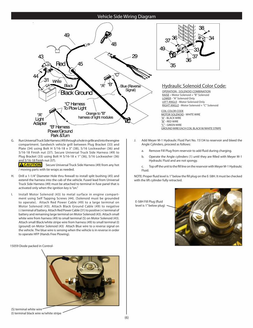
I. Install Motor Solenoid (43) to metal surface in engine compart-ment using Self Tapping Screws (44). (Solenoid must be grounded to operate). Attach Red Power Cable (49) to a large terminal on Motor Solenoid (43). Attach Black Ground Cable (49) to negative (-) terminal of battery. Attach Red Power Cable (31) to positive (+) terminal of battery and remaining large terminal on Motor Solenoid (43). Attach small white wire from harness (49) to small terminal (S) on Motor Solenoid (43). Attach small Black/white stripe wire from harness (49) to small terminal (I)(ground) on Motor Solenoid (43) Attach Blue wire to a reverse signal on the vehicle. The blue wire is sensing when the vehicle is in reverse in order to operate HFP (Hands Free Plowing).
Vehicle Side Wiring Diagram
E-58H Fill Plug (fluid level is 1” below plug)
Hydraulic Solenoid Color Code:OPERATION - SOLENOID COMBINATIONRAISE - Motor Solenoid + “B” SolenoidLOWER - “A” Solenoid Only LEFT ANGLE - Motor Solenoid OnlyRIGHT ANGLE - Motor Solenoid + “C” Solenoid
COIL COLOR CODEMOTOR SOLENOID - WHITE WIRE“A” - BLACK WIRE“B” - RED WIRE“C” - GREEN WIREGROUND WIRE EACH COIL BLACK W/WHITE STRIPE
(6)
(S) terminal white wire(I) terminal black wire w/white stripe
15059 Diode packed in Control-
J. Add Meyer M-1 Hydraulic Fluid Part No. 15134 to reservoir and bleed the Angle Cylinders, proceed as follows:
a. Remove Fill Plug from reservoir to add fluid during charging.
b. Operate the Angle cylinders (1) until they are filled with Meyer M-1 Hydraulic Fluid and are not spongy.
c. Top off the unit to the fill line on the reservoir with Meyer M-1 Hydraulic Fluid.
NOTE: Proper fluid level is 1” below the fill plug on the E-58H. It must be checked with the lift cylinder fully retracted.

(7)
For snow plow light installation see separate instructions.
Orange wire on Harness (49) will attach to both orange wires of the “B” harness supplied in the Light Module Kit. Reference Form 1-757
Route Cables “C” (Yellow) from module to Harness (49). Connect both “C” Harness female ends to the male corresponding ends of the Harness (49).
Connect both male ends from the snow plow light to the female ends on the Plow Side Harness (29).
Check snow plow light blinkers to make sure the wires have not been reversed.
Note: All electrical connections should have both ends coated with a dielectric grease, Meyer Part No. 15632, prior to final installation. This will ensure a good connection and help in preventing corrosion.
K. Refer to Operation and Maintenance Manual for complete controller operation.
L. After all electrical connections have been made the drop speed of the plow may be evaluated / adjusted. To adjust, loosen the hex nut and adjust in to slow the drop speed and out to make it faster. After ideal drop speed it achieved, retighten the hex nut. See below.
After cycling of the plow, recheck oil level.
E-58H Lower Adjustment (left side of vehicle):Loosen jam nut and turn screw clockwise to slow the drop of the plow and counter clockwise to speed the drop of the plow. Tighten jam nut
M. Assemble adjustable stacking stop bolts to lift frame (11) using 5/8-11 x 2-3/4” bolts (18), lockwashers (21) and jamnuts (55). See below.
Note: Adjustment must be made after moldboard assembly is installed. Adjustment bolts (61) should make contact with the a-frame before any part of the A-Frame/ Sector or moldboard come in contact with the lift arm and, or hydraulic unit while raising the snowplow or stacking snow. Moldboard should be checked in all positions.

Mount Plow To Vehicle
F. Attach crankstand to lift frame.
E. Remove crankstand from a-frame.
D. Adjust crankstand until it is no longer in contact with the ground.
B. Twist handle on driver side to disengage the notch that locks open the pins.
G. Remove weather cover on male end and connect one piece electrical plug. The spring loaded cover will lock one piece plug.
A. Pull vehicle into plow assembly and push plow assembly forward an inch or two.
C. Push back on lift frame until pins spring thru mount on vehicle.
For Mounting and Dis-mounting instructional video’s please visit www.youtube.com/meyerproducts
(8)
Meyer Products assumes no responsibility for installations not made in accordance with these instructions.
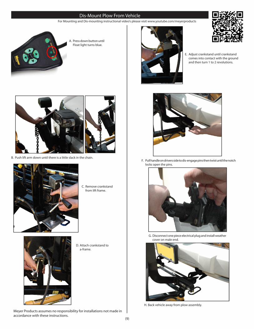
Dis-Mount Plow From VehicleFor Mounting and Dis-mounting instructional video’s please visit www.youtube.com/meyerproducts
A. Press down button until Float light turns blue.
Meyer Products assumes no responsibility for installations not made in accordance with these instructions.
B. Push lift arm down until there is a little slack in the chain.
C. Remove crankstand from lift frame.
D. Attach crankstand to a-frame.
E. Adjust crankstand until crankstand comes into contact with the ground and then turn 1 to 2 revolutions.
F. Pull handle on drivers side to dis-engage pins then twist until the notch locks open the pins.
G. Disconnect one piece electrical plug and install weather cover on male end.
H. Back vehicle away from plow assembly.
(9)

PRE-DELIVERY INSPECTION Vehicle Make: Vehicle Model: Vehicle Year: Vehicle VIN#: Vehicle FGAWR: Installing Company:
Mounting Type: Plow Type: Drive Pro 5.0 6.0 6.8 7.6
Hydraulic Serial Number: Moldboard Serial Number:
Comments:
Inspected By: W.O.# Date:
Customer Signature:
All bolts torqued to specification Suspension interference Clevis height in inches Diode Installed Trip springs adjusted Lift Chain Adjusted Check for hydraulic fluid leaks Hydraulic fluid Level Dielectric grease applied to ALL electrical connection All wires/modules secured Plow Stops Adjusted (plow cannot bump hyd. unit) Controller Operation Controller Turns Off when vehicle shut off
Plow Operation Up Plow Operation Left Plow Operation Right Plow Operation Down Plow Drop Speed Adjusted Plow Light Blinker Left & Right Operation Plow Light Low & High Beam Operation Plow Lights Adjusted Plow Mount/Dismount reviewed with Customer Plow Operation reviewed with Customer HFP (Hands Free Plowing) reviewed with Customer Warranty/Registration/Owners Manual
reviewed with Customer
(10)
Serial Number Decal LocationsE-58H unit serial number is attached to the cover.
Moldboard serial number is attached to the back of the moldboard.
Clevis height
9-1/2”

(11)
CUTTING EDGE KITS DEFLECTOR KITS PART NO. DESCRIPTION Steel Rubber Urethane Molded Rubber Poly 09320 DP 5.0 STEEL 08172* N/A N/A N/A 08238 N/A 09270 DP 6.0 STEEL 08175* 08237 08116 12036 08103 N/A 09274 DP 6.8 STEEL 08176* 08236 08277 13071 08107 12706 09275 DP 7.6 STEEL 08178* 08189 08119 12039 08109 12078 09278 DPP 7.6 POLY 08178* 08189 08119 12039 08109 12078*
Drive Pro Moldboard Accessories
Controllers and Controller Accessories
*Included with moldboard
22790XJoy Stick
22690XPistol Grip(standard)
22695XPistol Grip DLX
22154Touch Pad
(need 07691 adapter)
22799Joy Stick
Cradle Mount
22798Pistol Grip
Cradle Mount
2281545-Degree
Cradle Adapter
22801 (10”)22844 (20”)Floor Mount
Please visit http://www.meyerproducts.com/plows/lotpro.aspx for a complete listing of accessories
© 2012 Printed in the U.S.A.
Meyer Products LLC18513 Euclid Ave. • Cleveland, Ohio 44112-1084
Phone 216-486-1313www.meyerproducts.com• email [email protected]