Embed Size (px)
Citation preview
External Combustion Chamber Stpves
F. A. BERCZYNSKI * ' John Mohr & Sons, Chicago, Illinois
INTRODUCTION The continued increase in blast furnace production resulting from the
use of beneficiated burdens, auxiliary fuels and higher hot blast tempera- tures has given extra impetus to the search for methods that will increase the output of blast furnace stoves. This search has led to the use of high temperature refractories, the developnlent of new stove operating tech- niques,and auxiliary equipment, and a thorough investigation of the heat transfer process. Improvements in stove construction, on the other hand, have been lagging. Structural failures in stoves operating at extremely high temperatures and gas rates together with the short cycles common to present practices suggest improvements are necessary. The object of this paper is to shed some light on the cause of the most serious stove failure and to suggest a design that can prevent its occurrence while at the same time increasing the stove checker mass.
INTERNAL COMBUSTION CHAMBER STOVE FAILURES The demand' for higher hot blast temperatures has overtaxed stoves of
conventional designdo the extent that serious problems have arisen, the most predominant being:
I. The melting and deformation of colnbustion chamber, donle and upper checkerwork refractories.
2. Destruction of the combustion chamber and checkerwork resulting from a "cork screwing" of the checkerwork colunm.
3. Combustion chamber tilting. 4. Combustion chamber short circuits.
Engineers and operators have endeavored to elinlinate these problenls through improved internal combustion chaniber stove design and operating techniques.
* Chief Engineer. ' 55
56 I . BLAST FURNACES - 1 .. :
The melting and deformation of conlbustioli chamber, dome and upper checkerwork refractories are obviously caused 'by overheating. Stove. teinperature control systems that. maintain preset dome and stack ten). . .
peratures by regulatingburner fuel-air ratio represent. one method of combating overheating. Another involves the use of.high energy burners to : ' ' . .
insure proper mixing of fuel and air within. the combustion chamber, . .
thereby eliminating secondary combustio'n in the upper reaches 'of the combustioli cliamber,'dome and top checkers. These methods and the use of high ,temperature refractories in areas sudjected to overheating have . .
drastically' reduced failures caused by refractory melting and deformation.. : . Coluninar checkerwork construction permits "cork screwiug" which in .
- turn 'tends to dest rG the combustion .chamber. Cork screwingcan be ' . . eliminated by using pilaster wall construction foi the stove bridge and ring .
. .
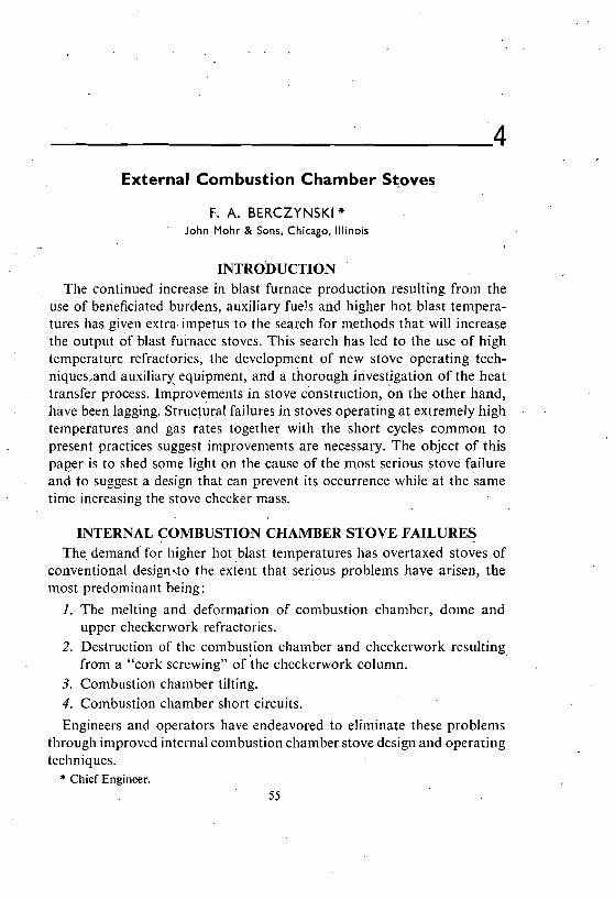
walls and a herringbone, bonded (refractory joints broken vertically and hoyizontally), staggered, construction for the checker-work proper as shown' . in Figure 1. The Mohr-Simplex Hot Blast S t o v e k the only design which ..
utilizes this type of checkerwork construction. ..
.Co'mbustion chaniber tiltihg is caused by the'diffe1:ential expansion of the walls forming the chamber. This uneven expansion causes the chamber '
to tilt toward the checkerwork column thereby reducing the latter's cross- '
sectional area. In extreme cases,' failures i l l . the upper,portion of the ' ' .
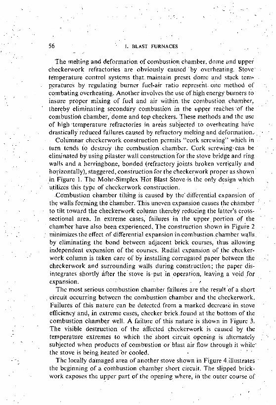
chamberhave also been experienced.. The construction shown in ~ i g u r e 2 . .
lninimizes the effect of differential expansion in,combustion chamber walls . .
by eliminating the bond between adjacent brick courses, 'thus allowing . .
independent expansion of the courses. Radial expansion of the checker- work column is taken care of b i installing corrugated paper between tlie , . : checkerworkand surrounding walls during construction; the paper djs- integrates shortly after t h e stove is--put 'in operation, leaving a void ,for expansion. . .,
The most serious combustion chamber failures are the result o f a short '
.
circuit occurring between the con~bustion chamber and the checkerwork. Failures of this nature can be detected from a marked decreac,e in stove efficiency and, in extreme cases, checker brick.found at the bottom of the
,
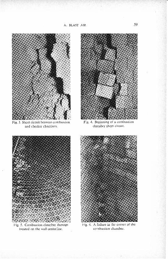
combustion chamber well. P failure of this nature is shown in Figure 3; .
The visible destruction of the &ected checkerwork is caused by the , .
temperature extremes to which the short circuit opening is alternately .. ..
subjected when products of combustion or blast air flow through i t while- , . the stove is being heated'or cooled.
The locaily damaged area of another stove shown in Figure 4.illustrates the beginning of a coiilbustion chamber short circuit. 'The slipped brick- - .
work exposes the upper part of the opening where, in the outercourse of ,
58 I . BLAST FURNACES .. . ,
1n addition to 'the dimage shown in Figure 4, oth:r:damage was also .. found., This damage was located o n the same side of the chamber, on the wall centerline, and contini~ed for 'a. considerable distance as shown in Figure 5. A probable explanation that these failures are t h e result of a . .
- . shearing force concentrated at the. centerline of the combustion chamber ' .
i s supported by the step, lines of the individual brick courses. Further, . ' .
Figure 6 shows a failure at the corner of the co~nbustion chamber, which indicates that the walls forming the combustion chamber oval were force- fully displaced. . '
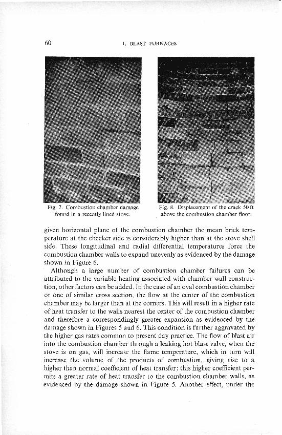
While repairing the hot blast valve of a ;ecently lined stove'which .was carefully dried out and heated to a dome temperature of 1500°F, cracks were found in the combustion chamber wall opposite"t11e hot blast valve. , . ' opening. Fu~tli.er'exanunati'on sliowed that this crack was located approxi- mately o n the ceriterline of the combustion charhber, on the checker side, and ran continuously from a fe-w feet above the combustion chamber floor to approxinlately 25 to 30 ft below the top where it became lost in. the . ,
mortar joints. Figure 7 sl~dws. a partial view of this crack running from course to course, alternately through brick and,'nlortar joint. Approxi- ...
mately 50 ft above the combustion .chamber floor, the course of the crack was displaced as shown in Figure 8..,Cracks.w&re also observed' at the corners of the .combustion chamber.
I n the case of the damage shown in .Figures 3 and 4, it 'can be assumed . ., 'that hot fAce expansion, the reaktion of the refractory with the dust in the . . gas and a leaking hot blast valve assisted expansion pressures in causing the . . ' .'
damage. In the c a s e ' o f - ~ i ~ u r e s 5 and 8, however, the damage can only be "
explained by the ,differential espansion.of the combustion chamber walls . .
and the resulting stresses. . . .
. ,
POSSIBLE CAUSES OF THE OBSERVED COMBUSTION . '
CHAMBER DAMAGE The differential expansion of a refractory.wall.is a consequence of vari-
able heating. Considering the internal cornbustio~l chambei- shown in Figure 2, it will be noted that its construction is not susceptible to. uniform heating. The wall adjacent to the stoveshell is uniforn~ly and well insulated ;
,
'accordingly, heat transfer and w'all temperature are uniform throughout. , Contrary to this, the wall temperature on the checker side decreases from . ..
- top to bottom. At the-upper end of the wall it can be assumed that both . .
sides of the wall are approximately at the same temperature, while a t the bottom a difference of approximately 1900°F between the two sides is possible. 'The nlean temperature of the brick wall is therefore very high a t the top 'and considerably lower at the bottom. It follows that in any
A. BLAST AIR 6 1
circumstances just described, is that a secondary flame is generated at the hot blast opening; this flame when directed continuously against the same
. portion of a wall produces large local expansions, resulting in damage similar to that shown in ' ~ i ~ u r e s 3 and 4. Finally, it should be noted that extended service interruptions and excessive fluctuations in hot blast tem- perature change the temperature distribution in the combustion chamber wall, adding to the problem.
The damage and failures shown in Figures 3 to 8 occurred in stoves operating at donie temperatures under 2300°F. Refractories used in the . combustion chamber walls of these stoves have a 40 to 45 pct AI2O3 content.
METHODS TO OVERCOME THE OBSERVED COMBUSTION CHAMBER DAMAGE
In the design of a hot blast stove the consideration of paramount importanc~ is structural stability.' To illustrate the effect that proper internal combustion chamber stove construction can have on reducing combustion chamber damage, consider the following: In over 150 in- stallations of the Mohr-Simplex Stove, only 2 pct have experienced com- bustion chamber damage. Refractories used in the constructio~l of the combustion chambers of these stoves have a maximum alumina content of 42 pct. The use of high alumina refractories with their superior load-bearing qualities at elevated temperatures can also. reduce the magnitude and frequency of combustion chamber damage which leads to short circuiting failures.
Variable heating, which causes combustion chamber damage, can be eliminated by a complete segregation of the conibustion area from the checker area. This segregation can be accomplished through the use of the external coinbustion chamber stove. It is the object of the second part of this paper to describe the main features of the external combustion cham- ber stove and discuss ~ t s merits.
EXTERNAL COMBUSTION CHAMBER STOVES The complete separation of the combustion area from the checker area
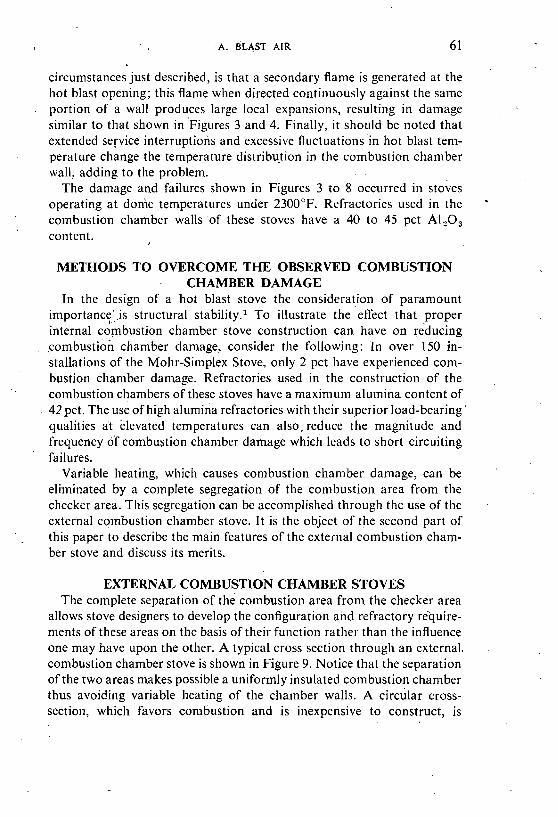
allows stove designers to develop the configuration and refractory require- ments of these areas on the basis of their function rather than the influence one may have upon the other. A typical cross section through an external. conlbustion chamber stove is shown in Figure 9. Notice that the separation of the two areas makes possible a uniformly insulated combustion chamber thus avoiding variable heating of the chamber walls. A circular cross- section, which favors combustion and is inexpensive to construct, is
62 I. BLAST FURNACES i ! ,
possible since configuration is not influenced by checkerwork temperature -
gradients. Repairs to the colnbustion chamber, should they be necessary due to refractory wear, are also s~mplified and safer. They can be effected without cold-blowing the checkerwork by using the burner fan to cool the co~nbustion clian~ber, cooling air being vented at the donle opening. ,
Lastly, the chamber can be positioned to acconunlodate local conditions, sijnplified piping and various gas burner arrangements.
e coMeusTlcm CHAMBER
e STOVE
Fig. 9. Cross section through an external conlbustion chamber stove
The area within"t11e stove shell nornlally occupied by the con+ bustion chamber, can be used to increase the heating surface of a given
. stove by 20 to 40 pct. With this additional heating surface, hot blast temperature demands can be met with reasonable stove operating tem- peratures, gas rates and pressuies, and less expensive reTractory materials. This means lower initial and opesating expenditures. Future expansion can be achieved by the application of the operating tec11ni'~ues and high temperature refractories advocated for present internal combustion ch'amber stoves with the assurance that benefits to be derived therefrom will be fully realized.
The separation of the combu~tion chamber fro111 the stove proper is not a new idea. In 1928, ~arnegie ' Steel Company; Mingo Junction Works, found it necessary to increase the heating surface of their Blast ~ u i n a c e No. 4 stoves. To provide the necessary surface, the external combustion
, - A. BLAST AIR
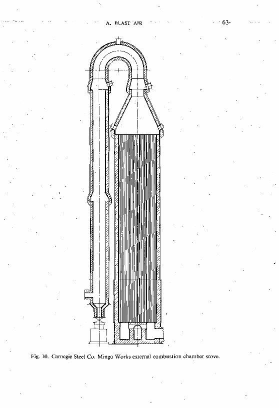
Fig. 10. Camegie Steel Co. Mingo Works external combustion chamber stove.
. .
64 . ' I. BLAST FURNACES -. . . .
chamber stove shownin ' Figure 10 was constructed. Inasmuch as this. . . .
'construction illvolved a radical departure fronl c6ive11tional practice a t . ' the tinle, it was thqughtiadvisable to bonlpare the operating ecdnomy of tllis design with existing 'three-pass stoves. .Tests were made, the results .of. . :...:
. . which indicated that tlle perfortnance of the stove, while satisfactory, had a 's ,
higher heat loss due to radiation ihenco~npared to the three-pass stovi: . . . : ' ;
The high operating costresulting froni these losses led to the abandonment :.
of the estkrna~ combustion chamber stove by Carnegie Steel Company: It is - : .
interesting tb hote, ho6&ver, that these stoves are still.in existence .tpday' . . . and are operated'as marginal equipment. : . , , ,
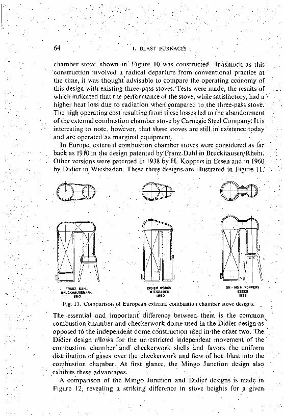
In ~u ro~e , ' ex t e rn s l coii~bustion chamber stoves were considered as &r. ' .' ..
back as 191'0 in \he design patented by:Franz.Dahl i n ~ruckhausen/~hein; : ' .-I Other versi6ns were patented in 1938 by-^: Koppers in Essln.and in 1960 '' ' ',
by Didier in Wiesbaden. These three designs. are. illustrated in Figure 1 1.: ' . ,
. . . FRANZ DAHL BRUWWUSENIRH
1910
DlDlER WORKS WIESBADEN
1 1960
DR - ING H KOPPERS , ESSEN 1938
Fig. 11. Comparison of European external con~bustion chamber stove designs. - The essential and i n ~ ~ o r t n n t differencp betweet;. theh is the common,, con~bustion chamber and checkerwork dome used in the Didier design.as
. , .
opposed to the independent dome construction used in.the other two. The ~ i d i e r design allows for the unrestricted illdependent movement of the ' . '
-combustibn. chamber ' and chPckeywqrk shells and favdri iile u~lifornl . .
distribution, of gases over the checkerwork. and flow. of hot blast into the :'
co~n~hs t ion chamber. At first glance, t h e Mingo Junction design also :.
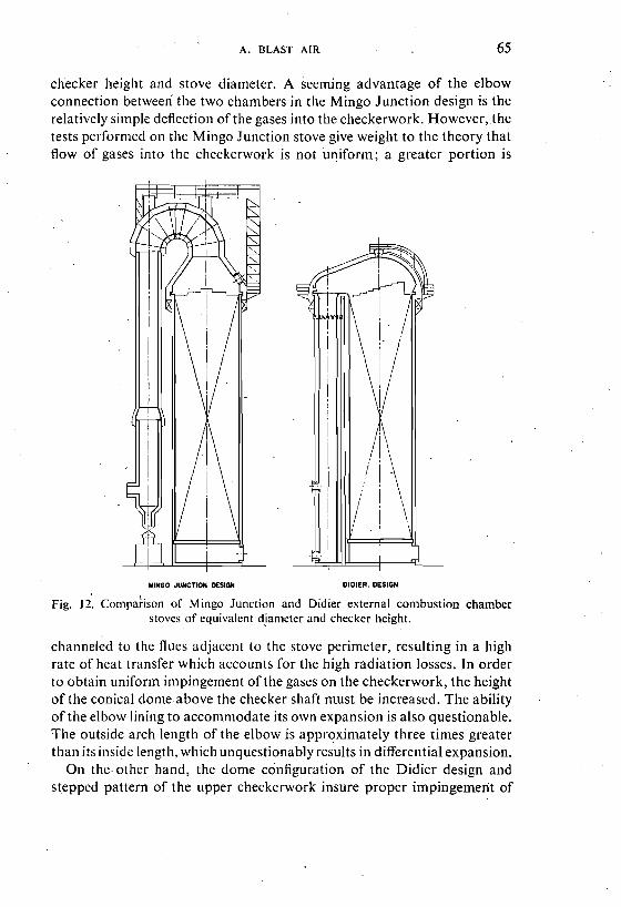
.exhibits these advantages. A comparison of the Mingo Junction and Didier designs is made in . .,
Figure 12, revealing a striking difference in stove heights for a given.
A. BLAST AIR 65
checker Ileight and stove diameter. A seenung advantage of the elbow connection betweeli the two chambers in the Mingo Junction design is the relatively simple deflection of the gases into the checkerwork. However,.the tests performed on the Mingo Junction stove give weight to the theory that flow of gases into the checkerwork is not uniform; a greater portion is
WING0 JUNCTWI DESlQN DIDIER. DESIGN
Fig. I 2. ~on~pa ; i son of M ingo Junction and Didier external con~bustion chamber stoves of equivalent diameter and checker height.
channeled to the flues adjacent to the stove perimeter, resulting in a high rate of heat transfer which accounts for the high radiation losses. In order to obtain unifornl impingement of the gases on the checkerwork, the height of the conical dome above the checker shaft rnust be increased. The ability of the elbow lining to accomn~odate its own expansion is also questionable. The outside arch length of the elbow is approximately three times greater than its inside length. whichunquestionably results in differential expansion.
On the other hand, the dome configuration of the Didier design and stepped pattern of the upper checkerwork insure proper impingement of
66 I . BLAST FURNACES
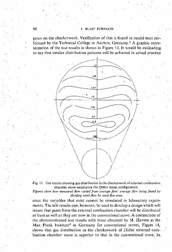
gases on the checkerwork. Verification of this is found in model tests per- I fdrnled by the Technical College in Aachen, Ger~nany." graphic repre-
sentation of the test results is shown in Figure 13. It would be misleading , to say that similar distribution patterns will be achieved in actual practice
Fig. 13. Test results showing gas distribution in the checkerwork of external conibustion chamber stove employing the Did~er dome configuration.
Figures slrow how rneasrrred flow ~wriedfioriz average flow: average flopolv beirrg forlrrd bv dividirig totnl flonl by roral flue area.
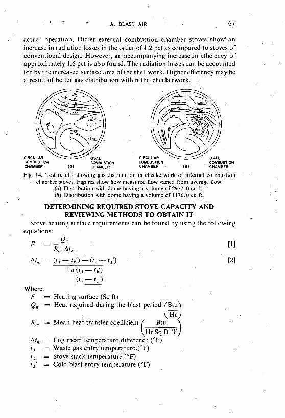
since the variables that exist cannot be simulated in laboratory experi- ments. The t&t results can, however. be used to develop a design which will insure that gases from the external combustion chamber will be distributed at least as well as they are now in the conventional stove: A conlparison of the aforernentio~led test results with those obtained by M. Hansen at the Max Plank Institute3 in Ger~nany for conventional stoves, Figure 14, shows that gas distribution in the checkerwork of Didier external com- bustion chamber stove is superior to that in the conventional stove. In
A. BLAST AIR 67
actual operation, Didier external cornbustion chamber stoves show' an increase in radiatior,, losses in the order of 1.2 pct as compared to stoves of conventional design: However, an accompanying increase ,in efficiency of approximately 1.6 pct is also found. The radiation losses can be accounted for by tlie increased su-rface area of the shell work. Higher efficiency may be a result of better gas distribution within tlie checkerwork.
COMBUSTlOh COMBUSTION CHAMBER ( 8 ) CHAMBER
Fig. 14. Test results showing gas distribution in checkerwork of internal combustion ' .
chamber stoves. Figures show how measured flow varied from average flow. (a) Distribution with dome havinga volume of 2977.0 cu ft. (b) Distribution with dome having a volume of 1176.0 cu ft.
DETERMINING REQUIRED STOVE CAPACITY AND REVIEWING METHODS TO OBTAIN IT
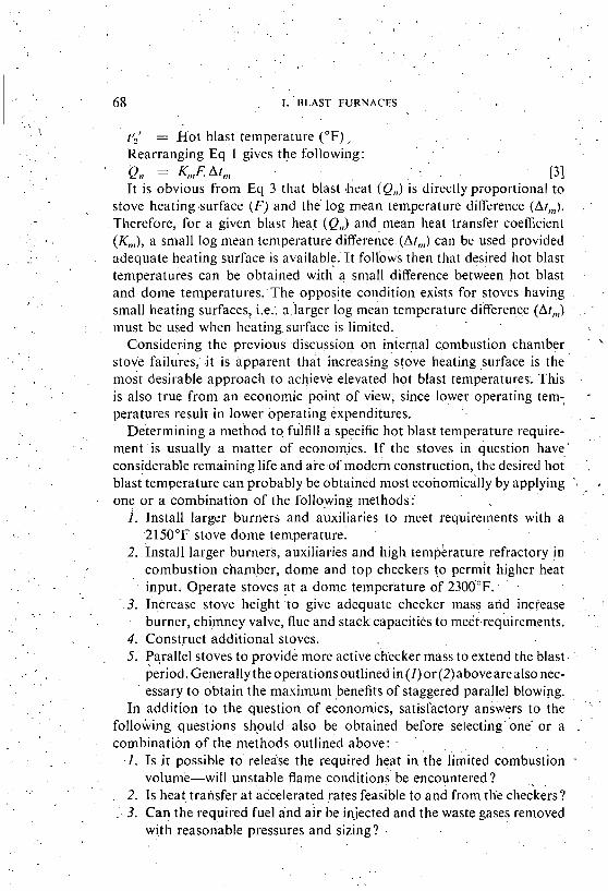
Stove heating surface requirements can be found by using the following equations:
At,,, = ( t , - t - ( t - t 111 ( t , - t ,')
( t 2 - f 1') Where:
F = Heating surface (Sq ft) Q,, = Heat required during the blast period Btu
K,,, = Mean heat transfer coefficient (4
At, = Log mean temperature difference (OF) t , = Waste gas entry ten~perature.(~F) t 2 = Stove stack temperature ( O F )
t,' = Cold blast entry temperature (OF)
68 I . BLAST FURNACES
15' = Hot blast temperature (OF) ,. . . Rearranging Eq 1 gives tile following: PI, = K,,,F, At,,, , . P I It is obvious from Eq 3 that blast )heat (Q,,) is directly proportional to
stove heating .surface ( F ) and t h i log mean temperature difference (At,,). : .
Therefore, for a given blast heat (Q,,) and mean heat transfer coefficient (Kt,,), a small log mean temperature differe~;ce.(~t,,,') can be used provided adequate heating surface is available.' It follbws then that desired hot blast t en~~era tu ies can be obtained with'' a sn~all difference betkeen hot blast and dome temperatures:The opposite condition exists for stoves llaving small heating surfaces, i.e.: a larger log mean temperature difference (At,,,) . . . -
must be used when heating,surface is limited. Consider.ing the previous discussion on internal conlbustion chamber . . '
stove f a i ~ ~ r e s , .it is apparent that increasing'stove heating surface is the '
.
most desirable approach to achievl elevated hot blast temperatures; This is also true from an economic point of view, since lower operating tern; - peratur& result in lower operating expenditures. .
Deterniining a method to fulfill a specific hot blast temperature require- ment is usually a matter of econolnjcs. If the stoves in question have.' considerable remaining life and aremof modern construction, tlie desired hot . blast'ten~~erature can probably be obtained most ecolomically by applying ', .
. . one or a combination of the following methods:'
1. Install larger burners and auxiliaries to llleet rquirements with a : ,
21 50°F stove dome temperature. 2. install larger burners, auxiliaries and high tenipkratu;e iefractory in ..
combustion chamber, dome and top checkers to higher heat . input. Operate stoves at a dome telilperature of 2300°F.. .
- . 3 . Increase stove height 'to give adequate checker mass arid increase .
burner, chimney valve, flue and stack capacities to meet-requirements. ' .
4. Construct additional stoves. 5. Parallel stoves to provide more active checker mass to extend tlie blast .
'
period.Generally the operationsoutlined in(l)or(2,)abovearealso nec-. essary to obtain the niaximunl benefits of stagge;ed parallel blowing.
In additionto the question of economics, satisfactory answers to the ' ' ' . .
following questions shpuld also be obtained before selecting' one' or a .' '
combination of the c net hods outlined above : - I. Is it possible to' release tlie required heat in the Gmited combustidn -
volume-will unstable flame conditions be encountered? . ,.
. 2. Is heat tralisfer at accelerated rates feasible to and from tlie checkers? . 3. Can the required fuel and air be injected and the waste gases removed
with reasonable pressures and sizing? .
A. BLAST AIR 69 . ,
H 4. Will a stove slenderness ratio-of 5, used by stove builders to assure
D wall stability and minimize stove pressure losses, be exceeded when stove height'is increased?.
5. Do the short heating and blast cycles encountered, particularly with - staggered parallel operation, present an operating problem?
6. Althougli present hot blast temperature demands can be met by the methods outlined, can future requirements be met by their extension?
In cases where stoves have reached the end of their useful life and must be.relined, the following methods, in addition to those listed previously, can be en~ployed to meet hot blast temperature requirements:
I. Convert existing stoves to the external combustion chambe? design. 2. Replace- existing stoves with larger conventional stoves. Heating Surface can be obtained most econon~ically through the use of
the external con~bustion chatnber design, i.e., to obtain 20 to 40 pct more heating surface, with a given checker, by any other means requires greater capital expenditures. This is due largely to the utilizationof existing stove shells and foundations made possible by the external combustion chamber design. Reduced burner and combustion air fan requirements resulting from smaller pressure losses and adequate combustion chanlber sizing are also factors.
Whether.considering methods to increase the output of existing o r new stove installations, a thorough overall appraisal is of utmost importance since additional capacity involves tremendous capital expenditures. Tlus appraisal must not only consider the present but also look to the future in order to anticipate ultimate requirements.
CONSTRUCTION OF AN EXTERNAL , COMBUSTION CHAMBER STOVE
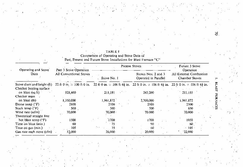
Early in 1962, a large Canadian steel manufacturer, began a thorough investigation of methods to increase the output of their Blast Furnace "C" stoves. Dimensional and operating data for these stoves are given in Table I. Included in the investigation were such schemes as :
I. Extension of existing stove shells to increase checker heating surface. 2. Relining existing stoves with high temperature refractories to perillit a
higher rate of heat input with larger burners and auxiliaries. 3. The installation of a new fourth stove. 4. Parallel and staggered parallel operation. 5. All possible conlbinatiolls of schemes (I) through (4). 6. External combustion chaniber stoves,
. .. . . . . . . . . . ~ . . . .
. . . . \. . . . ~ . . . . --
I . ' . . . . . . . . . ' . C. . . . . . . . .
. , TABLE I comparison of operating and Stove Data of
Past. Present and Future Stove Installations for Blast Furnace "C" - - - - -
present Stoves . , Future 3 Stove Operating and Stove Past StoLe ~ ~ e r a i i o n . . Operation
'Data All Conventional Stoves Stoves Nos. 2 and 3 All External Cornbustio~l . .
I Stove No. 1 Operated in Parallel Chamber Stoves .- w Stove diam'and height (ft) 22 ft 0 in. :.: 100ft 0 in. 22 ft 0 in. ;: 106 ft 43 in. 22 ft 0 in. i: 106 ft 43 in. 22 ft 0 in: :< 106 ft 43 in. r-
Checker heating surface on blast (sq ft) 121,600 211,181 . ' ' 243,200 211.181 ' .n
,Checker mass .. C on blast (Ib) . 1,350,000 1,961,872 ' 2,700,000 1,961,872
- ;a
Dome temp ("F) . 2100 2100 - , ' 2100 2300 , . 2.. stack tern pi"^) , , ~ 500 . 500 500 . . . 650 . . L?
. .
Wind rate (scfm) . . 70,000 70,000 70,000 70,000 - . .
Theoretical straight line . . hot blast temp ('E) 1500 '1700 . . . 1700 . . 1950
Time on blast (1nin.j 6 0 75 90 60, ' . . . Time o n gas (min.) . , 105 - 75 60 . . 105. .
Gas rate each stove'(cfm) . I ~,000 26,000 . 20,000 , . ' '22,000 . , . .
. .
. . . .
0
- . , . . . .
. . . .
. . . , . . - . 8 .
A. BLAST AIR 71
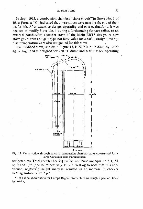
In Sept. 1962, a conlbustion chamber "short circuitY"in Stove No. 1 of Blast Furnace "C" indicated that these stoves were nearing the end of their , useful life. After extensive design, operating and cost evaluations, it was decided to modify Stove No. 1 during a forthcoming furnace reline, to an external con~bustion chamber stove of the Mohr-ERT* design. A new stove gas burner and gate type hot blast valve for 2000°F straight line hot blast temperature were also designated for this stove.
The niodified stove, shown in Figure 15, is 22 ft 0 in. in diam by 106 ft 43 in. high and is desiglled for 2300°F dome and 800°F stack operating
t OF STOVE
Fig. 15. Cross section through external conlbustion chamber stove constructed for a large Canadian steel manufacturer.
teniperatures. Total checker heating surface and mass are equal to 2.1 1,181 sq.ft and 1,961,872 lb, respectively. It is interesting to note that this con- version, neglecting height increase, resulted in an increase in checker heating surface of 26.7 pct.
* ERT is an abbreviation for Europa Regeneratoren Technik which is part of Didier Ipdustries,
I. BLAST- FURNACES
The condition bf Stoves Nos. 2 and 3 ofBlast Furnace "C" indicated they too were nearing the end of their useful life. Repairs could, however, be made at a reasonable cost to extend their life to the next scheduled reline. Since present hot blast temperature requirements could be met with the heating surface gained by the n~odification of Stove No. 1 , it was decided to repair Stoves Nos. 2 and 3. Provisions were made to convert these stoves to the external combustionchantber design with nlinihunt furnace down time in theevent of premature failure. Included in these provisions was the selection of an oversized gas burner for Stove No. 1 . This selection was based on operating.the furnace with Stove No. 1 and either of the other two stoves to maintain a straight line hot blast tempera- - ture of 1300°F for 90 min. while blowing 70,000 cfin wind.
In order to nteet present hot blast temperature dentands with one large stove and two smaller ones, it was decided to operate Stoves Nos._2 and 3 -
in parallel during their "on blast" period. In tliis way more activechecker mass could be provided during blast periods. The only ntodification necessary to the auxiliary equipment of Stoves Nos. 2 and 3 to permit this mode of operation was the installation of combustion air diffusers in their gas burners. This increased burner capacity from 16,000 cfnl to 20,000 cfm. Past, present and future operating conditions as well as stove data for Blast Furnace "C" stoves are sunt~narized i n Table 1.
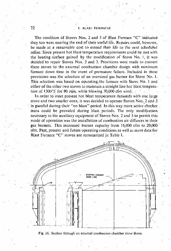
Fig. 16. Section through an external combustion chamber stovedome.
A. BLAST AIR 73
The co~nbustion chamber and checkerwork shells of the converted stove are covered by a common dome as shown in Figure 16. This dome overlaps both shells by the width of a box girder located below the dome and connected to it as well as to tlie checker chamber shell and upper portion of the conibustion chamber shell. The self supported conibustion chamber shell is joined to its upper portion by a three-wave expansion joint which takes up the differential expansion between shells since differential shell expansion cannot be avoided even by increasing the insulation of the con~bustion chamber. The shape of tlie dome is made u p of two quarter spheres, at each end, whose radii are laiger than the shafts they cover by the width of the box girder. These spheres are coniiected by a center piece which has the form of a half truncate'd cone. Donie lining assumes the same shape as the dome, insuring uniform distribution of gases over the checkerwork and flow of hot blast into the combustion chalnber.
The dome lining is'supported by the box girder, thus relieving the combustion and checker chaniber linings of dome weight. Following the shape of the dome shell, the portions above the chambers are formed by quarter spheres which are connected by a conical barrel type arch. The total expansion of the dome is taken up by the insulation a t the dome shell. Refractory quality and thickness for the dome are listed in Table 11.
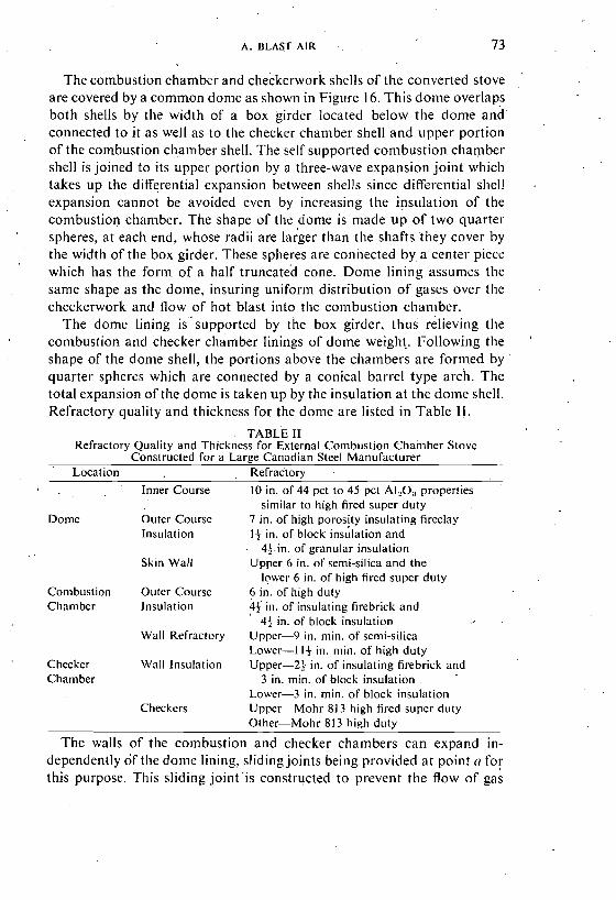
TABLE 11 Refractory Quality and Thickness for External Combustion Chamber Stove
Constructed for a LargeCanadian Steel Manufacturer Location Refractory ,
Inner Course 10 in. of 44 pct to 45 pct AI,O, properties similar to high fired super duty
Dome Outer Course 7 in. of high porosity insulating fireclay Insulation 1% in. of block insulation and
43in. of granular insulation Skin Wall Upper 6 in. of semi-silica and the
lower 6 in. of high fired super duty Conibustion Outer Course 6 in. of high duty Chamber Insulation 4% in. of insulating firebrick and
43 in. of block insulation ,
Wall Refractory Upper-9 in. niin. of semi-silica Lower-1 I j in. niin. of high duty
Checker Wall Insulation Upper-2Q in. of insulating firebrick and Chamber 3 in. min. of block insulation
Lower-3 in. min. of block insulation Checkers Upper-Mohr 813 high fired super duty
Other-Mohr 813 high duty
The walls of the combustion and checker chambers can e x p a ~ d in- dependently of tlie dome lining, sliding joints being provided at point a for this purpose. This sliding joint 'is coiistructed to prevent the flow of gas
74 I. BLAST FURNACES
or liot blast to tile-chamber shells. The radial expansion of the chamber ' . .
linings is. taken up by the insulatioh in the same manner as in thedorne. ' ~ e f r a c t o r ~ ~ u a l i t i e s a n d tliicknesSes for both chamberiare listed in Table 11.. , '
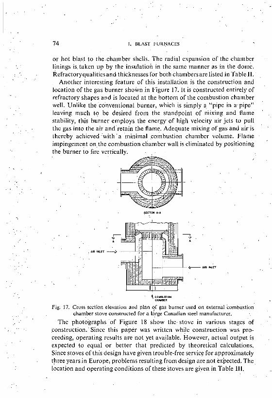
Another interesting feature of this installation is the construction and location of the gas burner shown in Figure 17. I t is constructed entirely of
'
refractory shapes and is located at the bottom of t l ~ e colnbustion chamber well. Unlike the'conventional'burner, which is simply a "pipe in apipe" ' .
leaving much to be desired from the standpoint of niixing and flame ' ,
stability, this burner employs the energy- of high velocity air jets to pull the gas into the air andretain the'flame Adequate mixing of gas and airis a
thereby achieved .with ' a niininial combustion chaniber volunie. Flan~e impingement ontlie cornbustion cliamber wall is eliminated by positioning the burner to fire vertically. . .
, AIR I K E T -
- C covsusrlm C W E R
Fig. 17. Cross section elevation and planqf gas burner used on external omb bust ion . , chamber stove constructed for a large Canadian steel n~anufacturer.
The photographs o f Figure 18 show t h e stove in various stages 'of . .
, . , construction.'Si~ice this paper was written while construction was pro- ceeding, operating results are not yet available. However, actual output is ' .
expected to equal or better that predicted by theoretical calculations. - Since stoves of this design have' given trouble-free service for approximately tjiree years in Europej problenls resulting froni design are not expected. The,
. . location and operating conditions of these Stoves are given in Table 111,
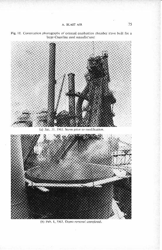
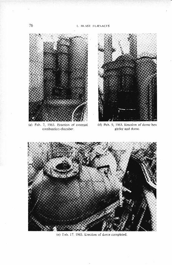
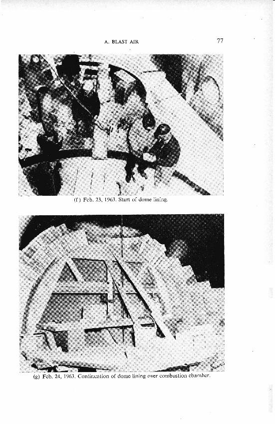
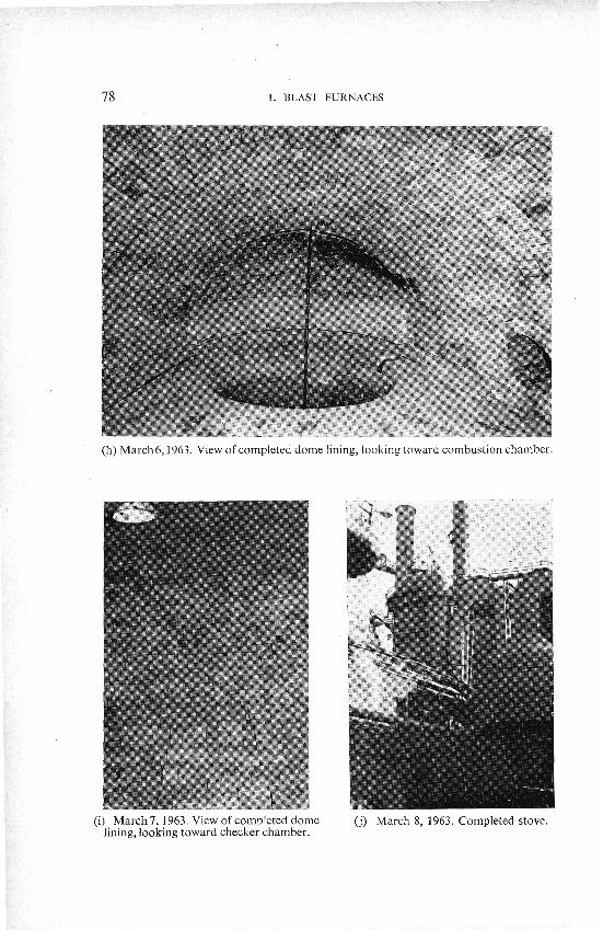
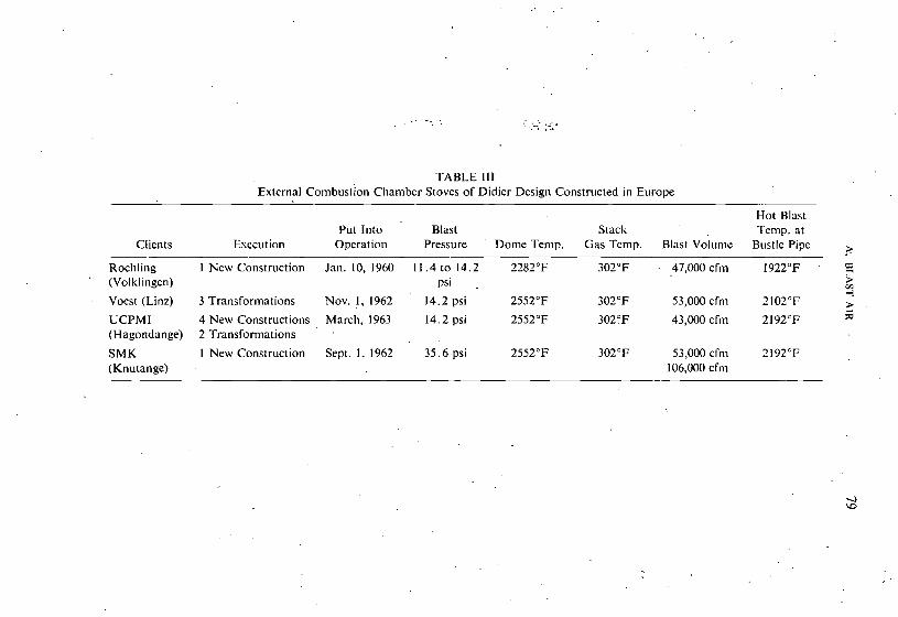
TABLE 111 External omb bust ion Chamber Stoves of Didier Design Constructed in Europe
Clients Esecution
Rochling 1 New Construction ' (Volklingen)
Voest (:Linz) 3 Transformations
UCPMI 4 New Constructions (Hagondange) 2 Transformations
SMK 1 New Construction (Knutange)
Put Into Blast Operat ion Pressure Dome Temp.
Jan.10,1960 11 .4 to14 .2 2282'F psi .
Nov. 1, 1962 14.2 psi 2552°F
March, 1963 14.2 psi 2552°F
Sept. 1. 1962 35.6psi 2552°F
-
Hot Blast Stach: Temp. at
Gas Temp. Blast Volume Bustle Pipe
302°F - 47,000 cfnl 1922°F ' P > V1 4
302°F 53,000 cfni 2102°F 5 3OZ0F 43,000 cfrn 21 92°F 3
302°F 53,000 cfnl 2192°F 106,000 cfrn
I . BLAST FURNACES . .
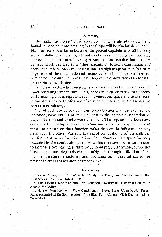
. . Summary '
The higher hot blast temperature requirements already evident and bound to becolile more pressing in the future 'will b~ placing demands on blast furnace stoves far i n excess of the present capabilities of all but very ' recent installations. xis sting internal conlbustion charnber.stoves operated at elevated temperatures have experienced serious conlbustion chamber '
.
damage which can lead to. a "short circuiting" between conlbustion and checker chambers. Modern construction and high temperature refractories - . .
haye reduced the magnitude and frequency of this damage but have not .
eliminated the cause, i.e., variable heating of the combustion chamber wall o n the checkerwork side.
By increasing stove heating surface, stove output can be increased despite '.
lower operating temperatures. This, however, is easier to say than acconl- , plish. Existing stoves represent such a tremendous space and capital c o ~ n l mitment that partial utilization of existing facilities to obtain the desired results is mandatory.
A tried and satisfactory solution to combustion chamber failures and increased;stove output a t minimal cost is the complete separation of . ' the,con~bustion and checkerwork ~ha~~ibe r s . 'T l i i s separation allows stove designers to develop the configuration and refractory requirements of tliese'areas. based o n their function rather than on ' the influence one may have upon the other. Variable heating of conibustion chamber walls can " - b e e1iminate.d by uniform 'insulation of the chamber. The space formerly . '
occupied by the conlbustion chamber within the stove proper can be used to increase stove heating surface by 20 to .40 pct. Furthermore, future hot blast temperature demands can. be safely met through utilization of the high temperature refractories and operating techniques 'advocated for present internalconibustion chamber stoves.
. . - References , . .
1. Mohr, Albert, Jr. and Fred Wille, "Analysis of Design and Construction of Hot . .
Blast Stoves," Iron Age, July 4. 1935. 2. Taken from a report prepared by Technische ~ochschu le (Technical College) in
Aachen for Didier. . 3. Hansen. Von Michael, ''Flow Conditions in Stoves Based Upon Model Tests." Paper presinted at the Sixth Session of the Blast Furn. Comm. (VDI) Dec. 18. I951 at Dusseldorf. ,