Embed Size (px)
Citation preview
Extending the Edge
Drawing CreationDrawing Creation
Productivity and Performance How-to Session
Ricky Black
Product Manager
Productivity and Performance How-to Session
Ricky Black
Product Manager
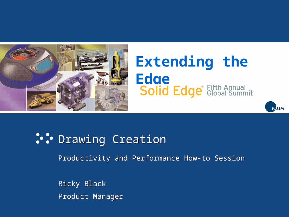
What has Solid Edge done?What has Solid Edge done?
• Improve Drawing View Creation and Update Performance each release (V9 – V14).
• Reduce Draft file size
• Improvements to Broken Views (V14)
• New drawing view types
– Paper Thin Sections (V12) - Sections of Sections(V12)
– Auxiliary of Auxiliary(V12) - Fold Isometric from Isometric(V12)
– Broken Out Section(V14)
– Reference Parts(V14)
• Greatly Improve Auto-balloon Performance V11 and V12
• Improve Drawing View Properties
• Improve Dimensioning and Annotations
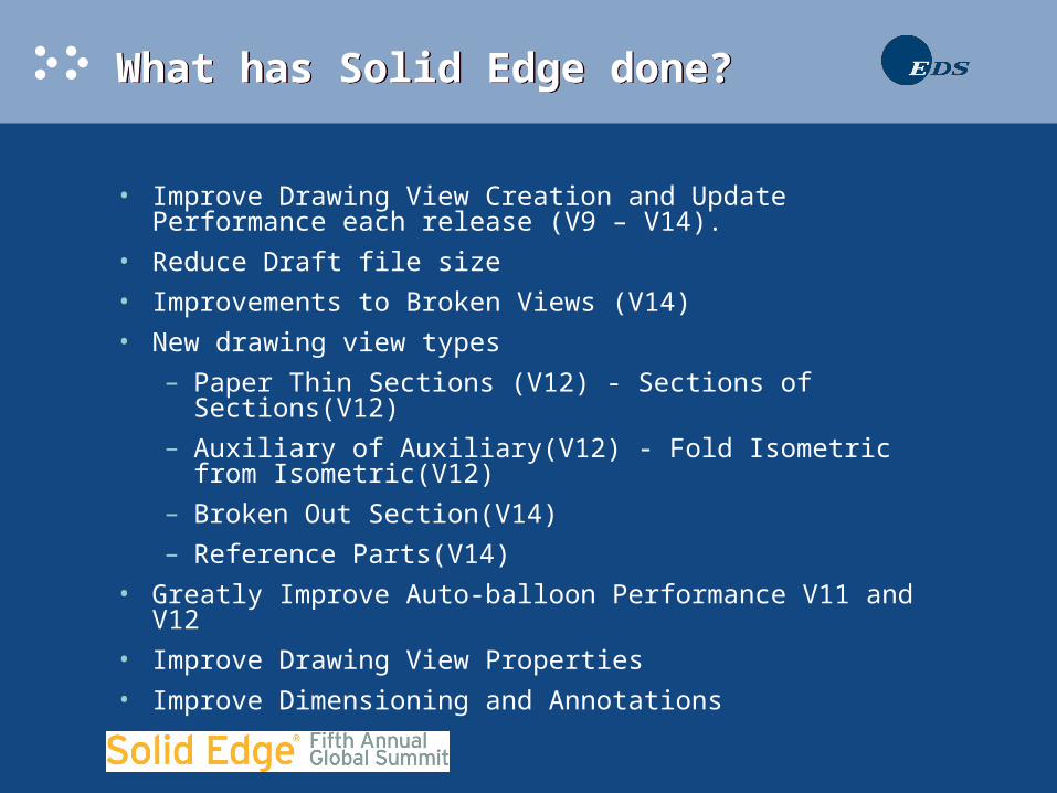
Drawing View PerformanceDrawing View Performance
Creation Time Test
0
5
10
15
20
25
30
8 9 10 11 12 14
Version
Ho
urs

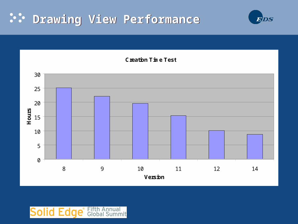
Drawing View PerformanceDrawing View Performance
Update Time Test
0
5
10
15
20
25
30
35
9 10 11 12 14
Version
Ho
urs
Drawing View UpdateDrawing View Update
• Before V14
– The entire drawing view was updated.
– All geometry in the drawing view was recomputed.
– Any dimension placed was subject to detach.
• With V14
– Only update the areas affected by model changes.
– Update time can be significantly faster than create time.
– Fewer dimensions will detach.
Drawing View Update ExampleDrawing View Update Example
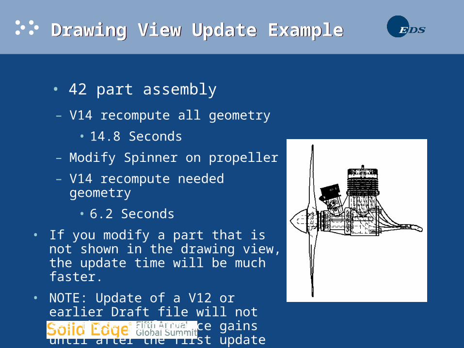
• 42 part assembly
– V14 recompute all geometry
• 14.8 Seconds
– Modify Spinner on propeller
– V14 recompute needed geometry
• 6.2 Seconds
• If you modify a part that is not shown in the drawing view, the update time will be much faster.
• NOTE: Update of a V12 or earlier Draft file will not see these performance gains until after the first update in V14.
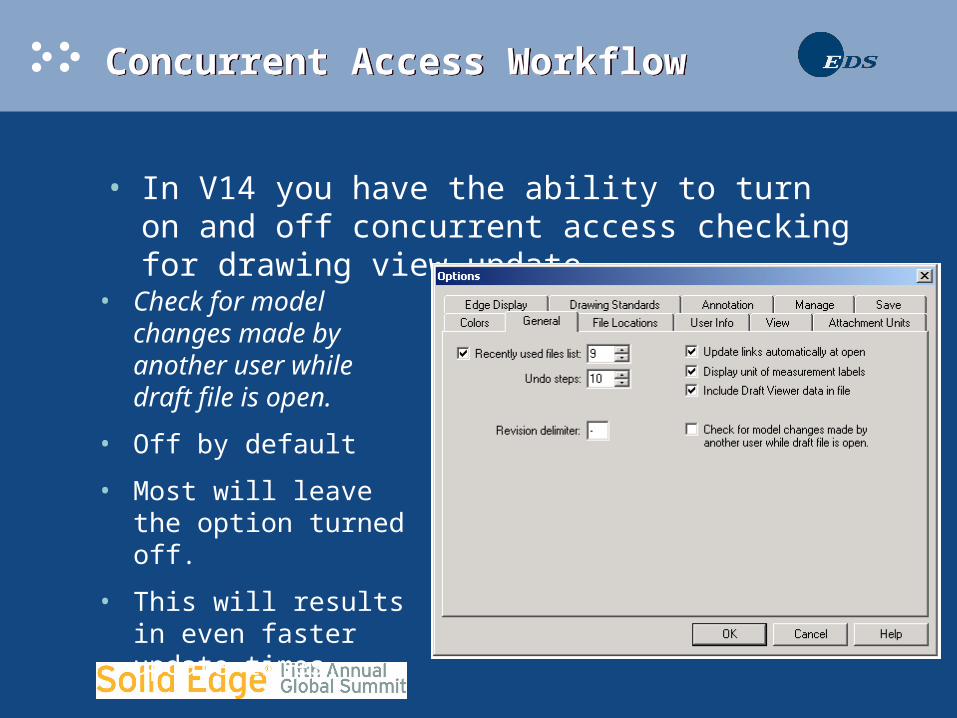
Concurrent Access WorkflowConcurrent Access Workflow
• In V14 you have the ability to turn on and off concurrent access checking for drawing view update.
• Check for model changes made by another user while draft file is open.
• Off by default
• Most will leave the option turned off.
• This will results in even faster update times.
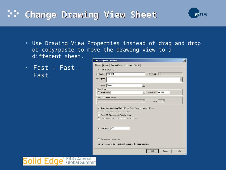
Change Drawing View SheetChange Drawing View Sheet
• Use Drawing View Properties instead of drag and drop or copy/paste to move the drawing view to a different sheet.
• Fast - Fast - Fast
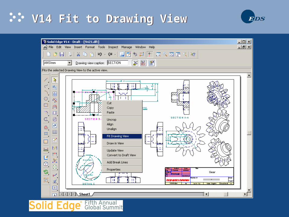
V14 Fit to Drawing ViewV14 Fit to Drawing View

V14 Fit to Drawing ViewV14 Fit to Drawing View
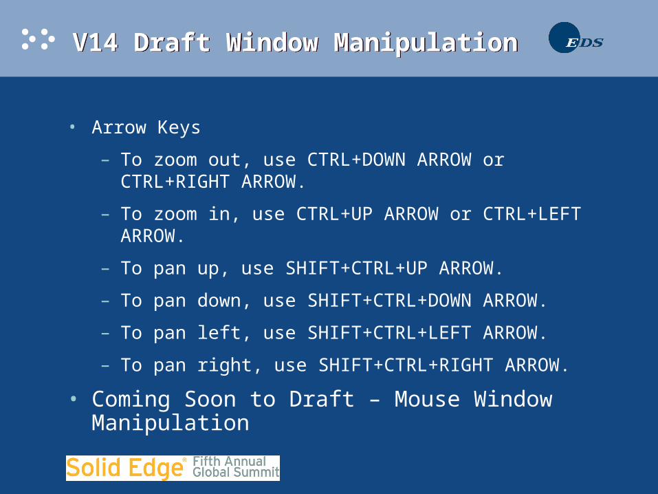
V14 Draft Window ManipulationV14 Draft Window Manipulation
• Arrow Keys
– To zoom out, use CTRL+DOWN ARROW or CTRL+RIGHT ARROW.
– To zoom in, use CTRL+UP ARROW or CTRL+LEFT ARROW.
– To pan up, use SHIFT+CTRL+UP ARROW.
– To pan down, use SHIFT+CTRL+DOWN ARROW.
– To pan left, use SHIFT+CTRL+LEFT ARROW.
– To pan right, use SHIFT+CTRL+RIGHT ARROW.
• Coming Soon to Draft – Mouse Window Manipulation
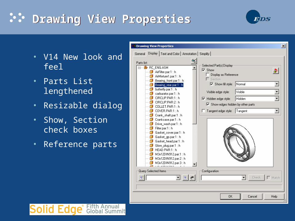
Drawing View PropertiesDrawing View Properties
• V14 New look and feel
• Parts List lengthened
• Resizable dialog
• Show, Section check boxes
• Reference parts

Drawing View PropertiesDrawing View Properties
• Fill style
• Restore Button.
• Match configuration and sectioning.
• Revolved Section View
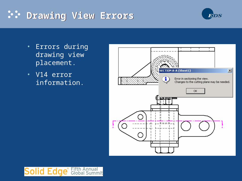
Drawing View ErrorsDrawing View Errors
• Errors during drawing view placement.
• V14 error information.
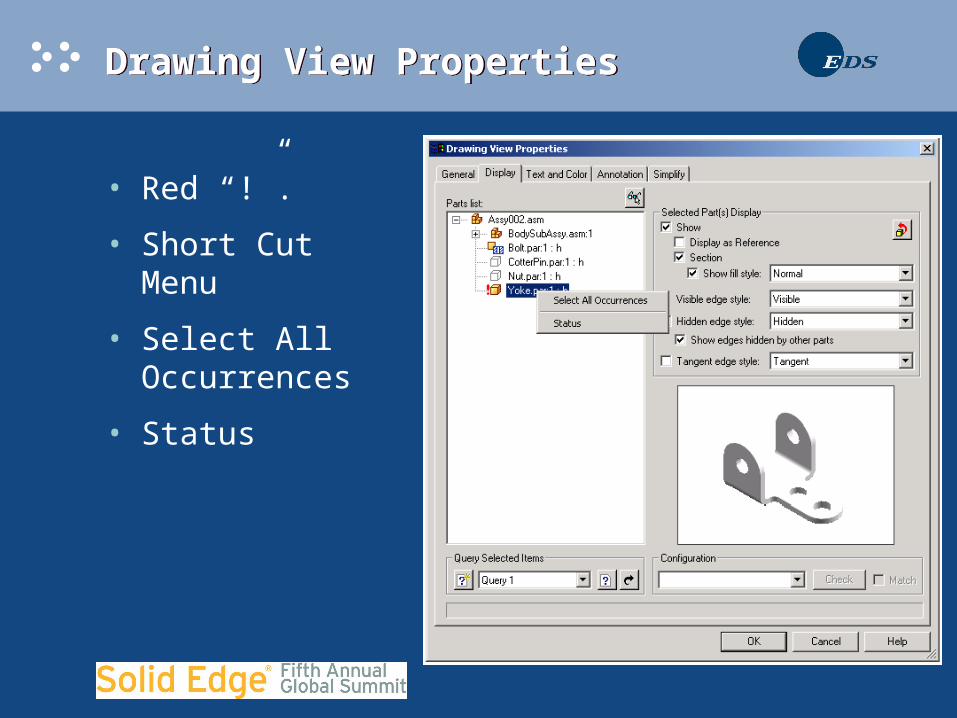
Drawing View PropertiesDrawing View Properties
• Red “!”.
• Short Cut Menu
• Select All Occurrences
• Status
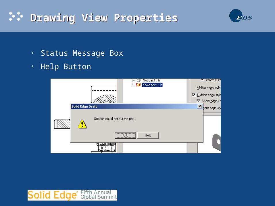
Drawing View PropertiesDrawing View Properties
• Status Message Box
• Help Button
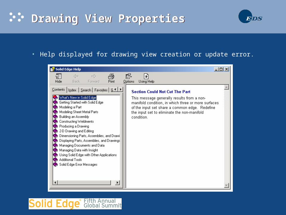
Drawing View PropertiesDrawing View Properties
• Help displayed for drawing view creation or update error.
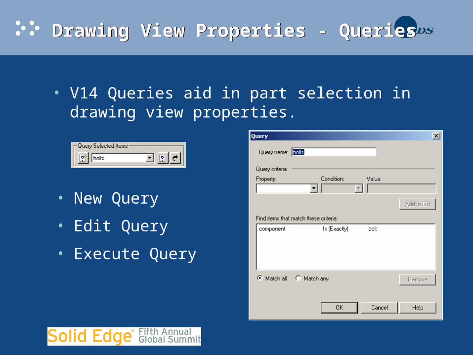
Drawing View Properties - QueriesDrawing View Properties - Queries
• V14 Queries aid in part selection in drawing view properties.
• New Query
• Edit Query
• Execute Query

Drawing View Properties - QueriesDrawing View Properties - Queries
• Some Types of Queries
– Part Properties – Much the same as assembly.
– Custom Part Properties
– Display results
– Eligible for Display
– Eligible for Sectioning
– Failed to Compute
– Edge Styles ( Hidden, Visible, and Tangent )
Drawing View Properties - QueriesDrawing View Properties - Queries
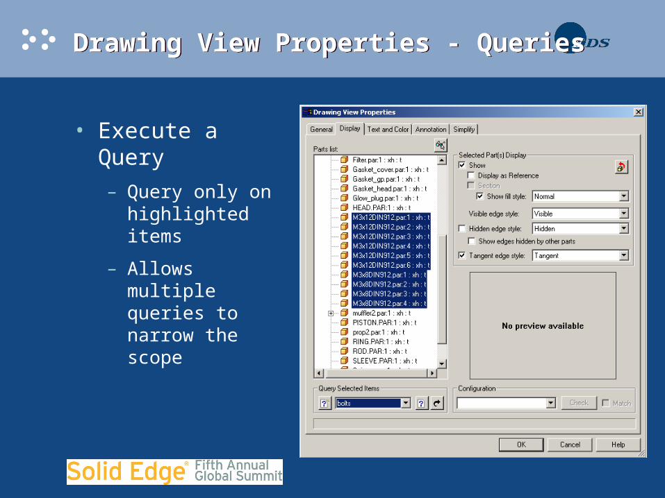
• Execute a Query
– Query only on highlighted items
– Allows multiple queries to narrow the scope

Drawing View Properties - QueriesDrawing View Properties - Queries
• Queries before view placement greatly improves performance.
• Use Model Display Settings
• 42 Parts Displayed
• 6.3 Seconds
• Query for not plastic parts.
• 2 Parts Displayed
• 1.5 Second
V14 Broken View EnhancementsV14 Broken View Enhancements
• You asked for it. We hear you!!!
• New Break Line Types
• Define removed areas
• Break in both directions
• Dimensions and annotations stick
• Folded broken views
• Folded broken section and auxiliary views
Broken ViewsBroken Views
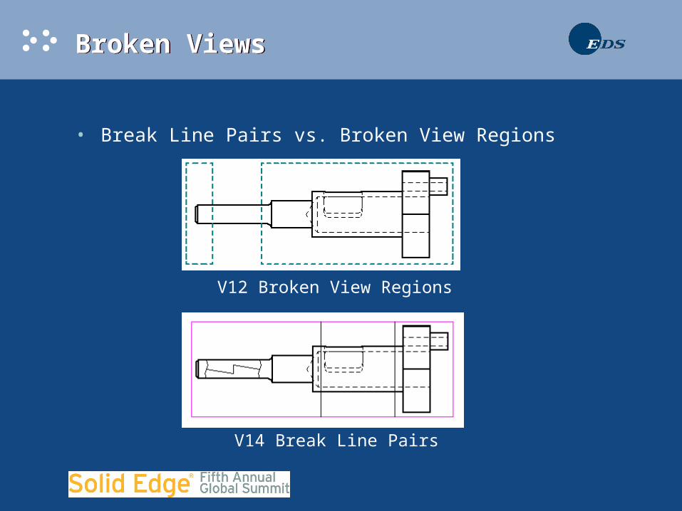
• Break Line Pairs vs. Broken View Regions
V12 Broken View Regions
V14 Break Line Pairs
Dimensions with Broken ViewsDimensions with Broken Views
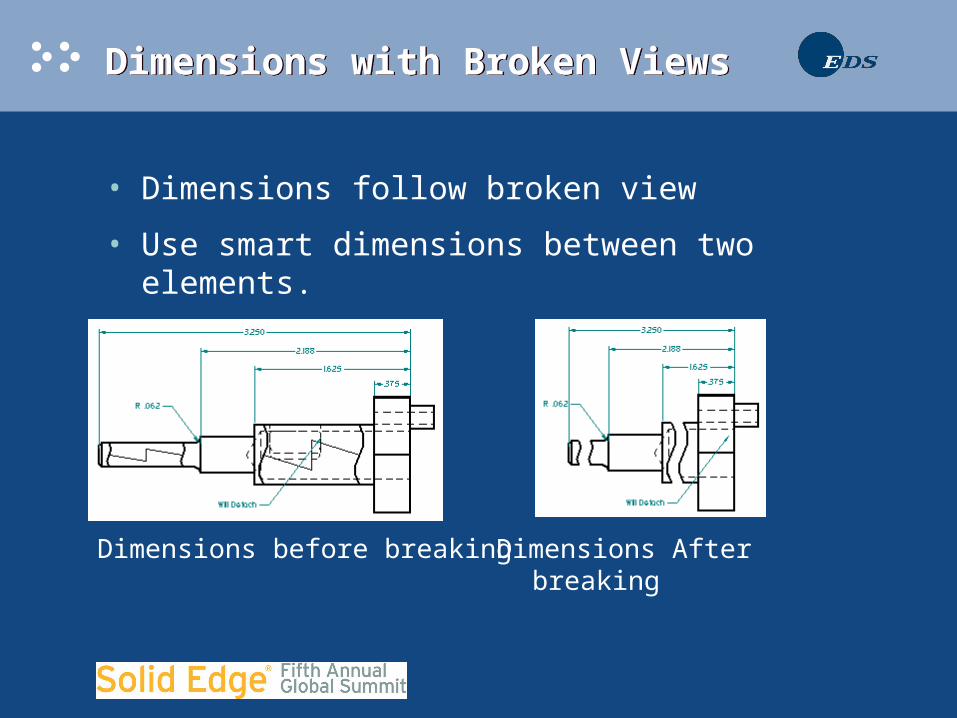
• Dimensions follow broken view
• Use smart dimensions between two elements.
Dimensions before breaking Dimensions After breaking
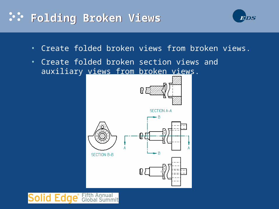
Folding Broken ViewsFolding Broken Views
• Create folded broken views from broken views.
• Create folded broken section views and auxiliary views from broken views.

Folding Broken ViewsFolding Broken Views

V14 Broken Out Section ViewsV14 Broken Out Section Views
• Create profile on one view
• Break another view (Most CAD systems apply the cut to the same view only!!)
• No assembly Cutaway needed to break the view
V14 Broken Out Section ViewsV14 Broken Out Section Views

V14 Reference PartsV14 Reference Parts
• Use Drawing view properties to specify reference part display.

V14 Rotate Drawing ViewV14 Rotate Drawing View
• V12 Rotate drawing view with rotate command
• V14 Rotate drawing view with Key-in or rotate command
• Retrieve dimensions work on rotated views
• Fold Views from rotated views
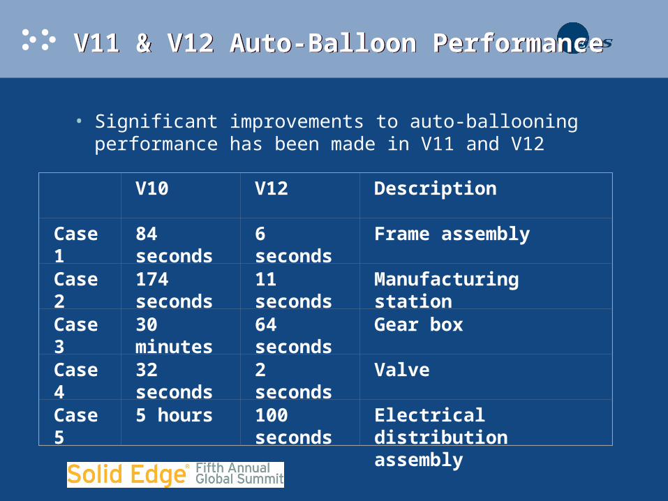
V11 & V12 Auto-Balloon PerformanceV11 & V12 Auto-Balloon Performance
• Significant improvements to auto-ballooning performance has been made in V11 and V12
V10 V12 Description
Case 1 84 seconds 6 seconds Frame assembly
Case 2 174 seconds
11 seconds Manufacturing station
Case 3 30 minutes 64 seconds Gear box
Case 4 32 seconds 2 seconds Valve
Case 5 5 hours 100 seconds
Electrical distribution assembly

Auto-Balloon PlacementAuto-Balloon Placement
• More Cosmetic balloon placement
Before V11 V11
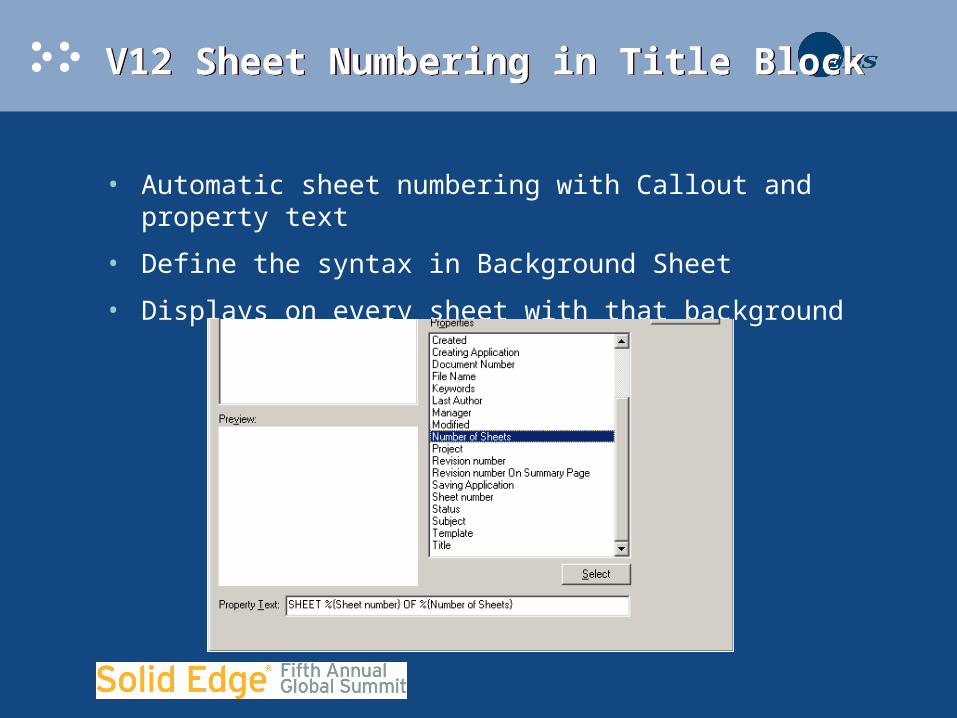
V12 Sheet Numbering in Title BlockV12 Sheet Numbering in Title Block
• Automatic sheet numbering with Callout and property text
• Define the syntax in Background Sheet
• Displays on every sheet with that background
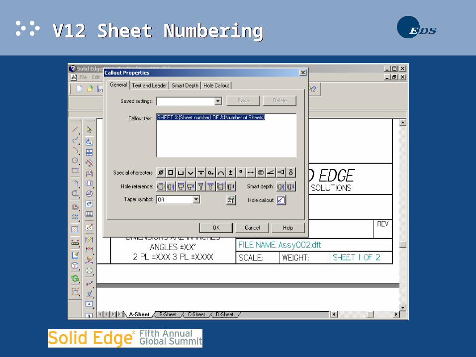
V12 Sheet NumberingV12 Sheet Numbering
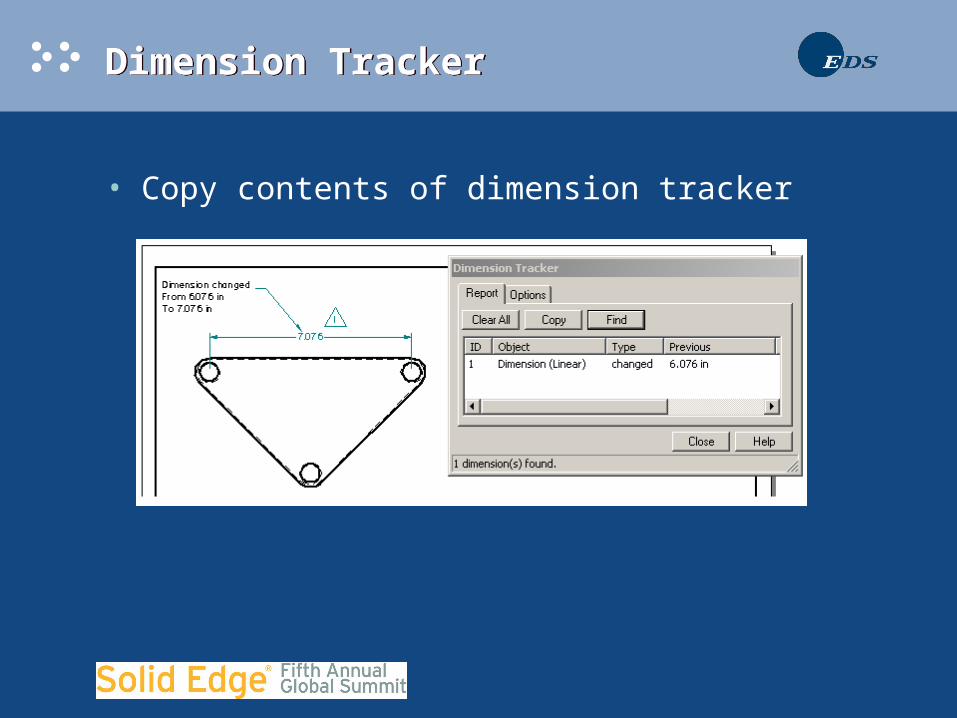
Dimension TrackerDimension Tracker
• Copy contents of dimension tracker

Line Up TextLine Up Text
• Menu Tools->Dimensions->Line Up Text
• Customize->Dimension 1
• Dimensions and annotations
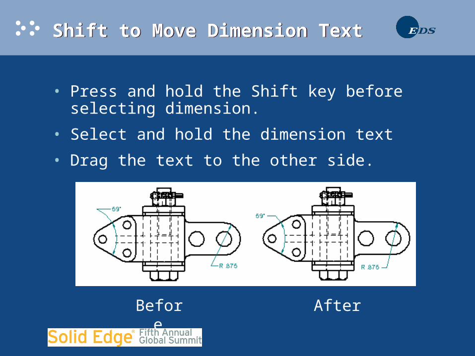
Shift to Move Dimension TextShift to Move Dimension Text
• Press and hold the Shift key before selecting dimension.
• Select and hold the dimension text
• Drag the text to the other side.
Before After
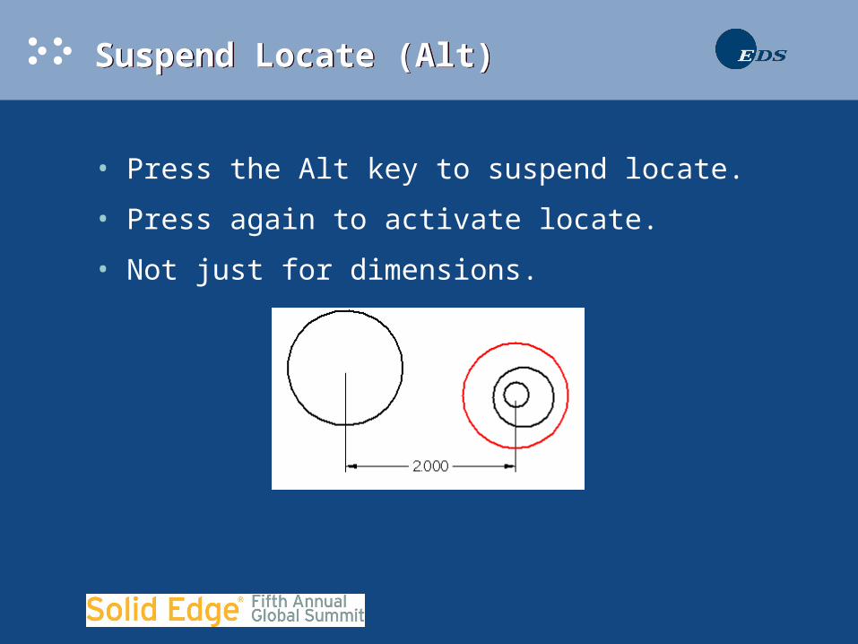
Suspend Locate (Alt)Suspend Locate (Alt)
• Press the Alt key to suspend locate.
• Press again to activate locate.
• Not just for dimensions.
Suspend Locate (Alt)Suspend Locate (Alt)
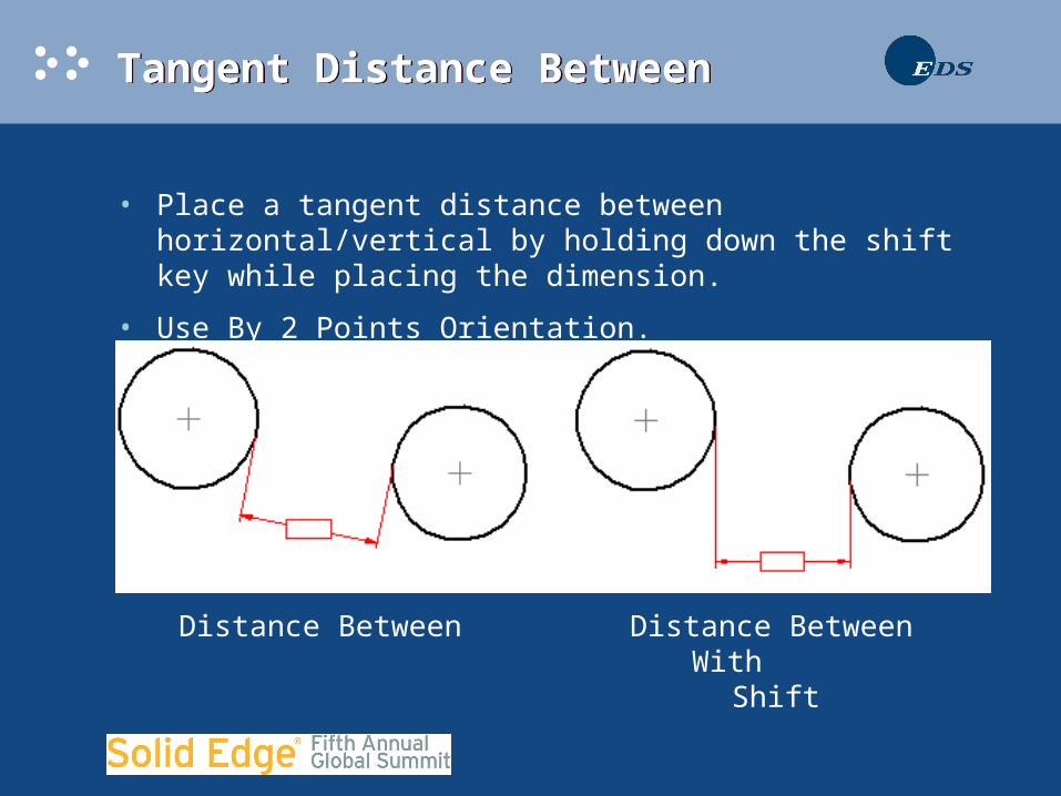
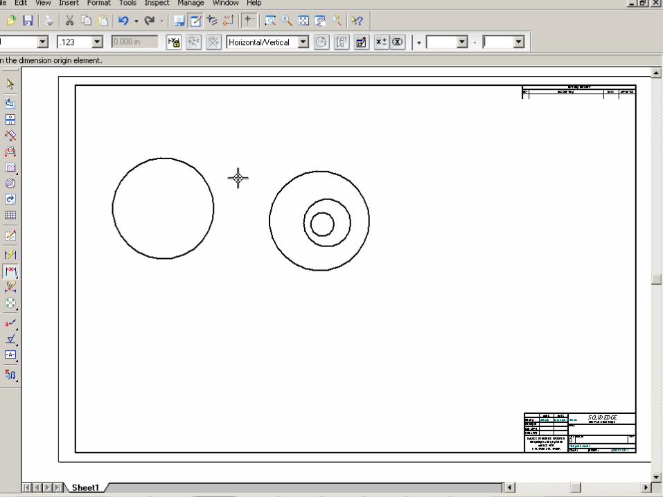
Tangent Distance BetweenTangent Distance Between
• Place a tangent distance between horizontal/vertical by holding down the shift key while placing the dimension.
• Use By 2 Points Orientation.
Distance BetweenWith Shift
Distance Between
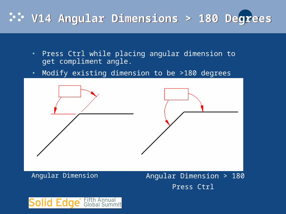
V14 Angular Dimensions > 180 DegreesV14 Angular Dimensions > 180 Degrees
• Press Ctrl while placing angular dimension to get compliment angle.
• Modify existing dimension to be >180 degrees
Angular Dimension Angular Dimension > 180Press Ctrl
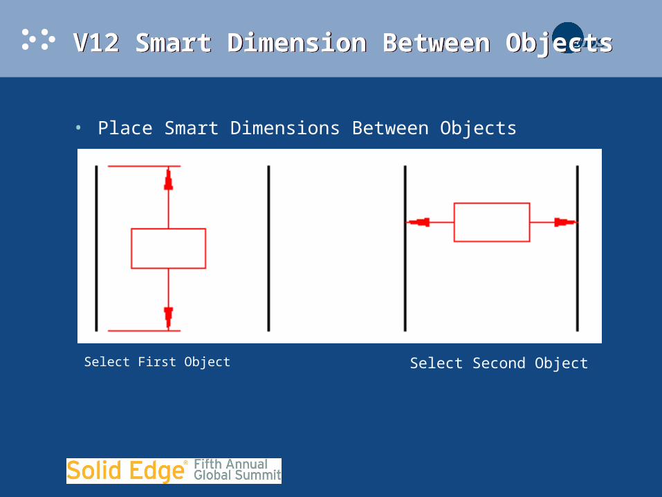
V12 Smart Dimension Between ObjectsV12 Smart Dimension Between Objects
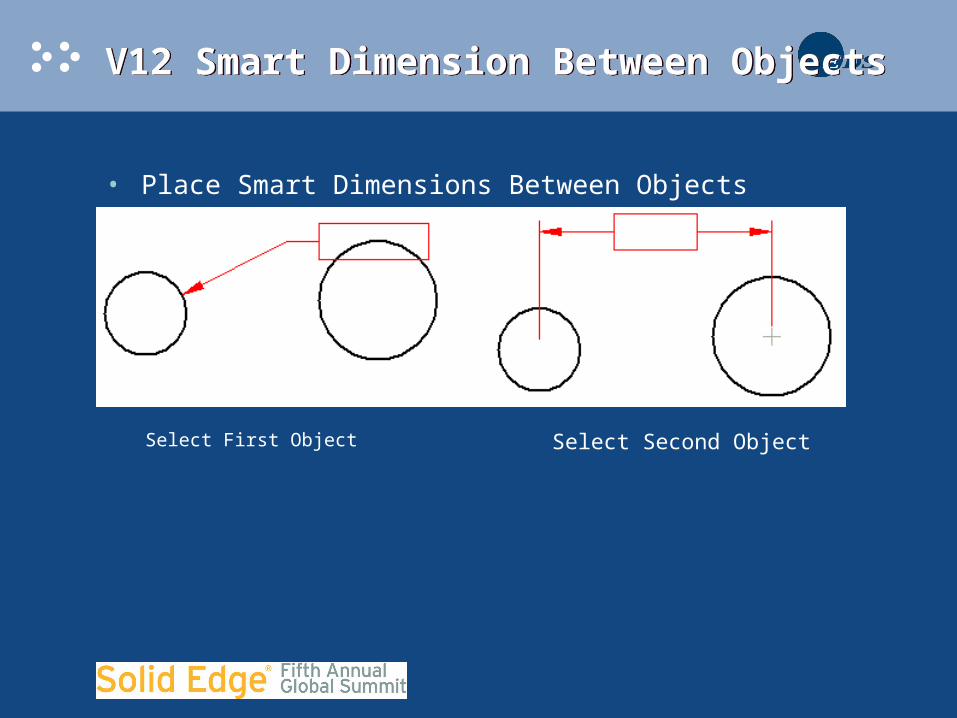
• Place Smart Dimensions Between Objects
Select First Object Select Second Object
V12 Smart Dimension Between ObjectsV12 Smart Dimension Between Objects
• Place Smart Dimensions Between Objects
Select First Object Select Second Object
V12 Smart Dimension Between ObjectsV12 Smart Dimension Between Objects
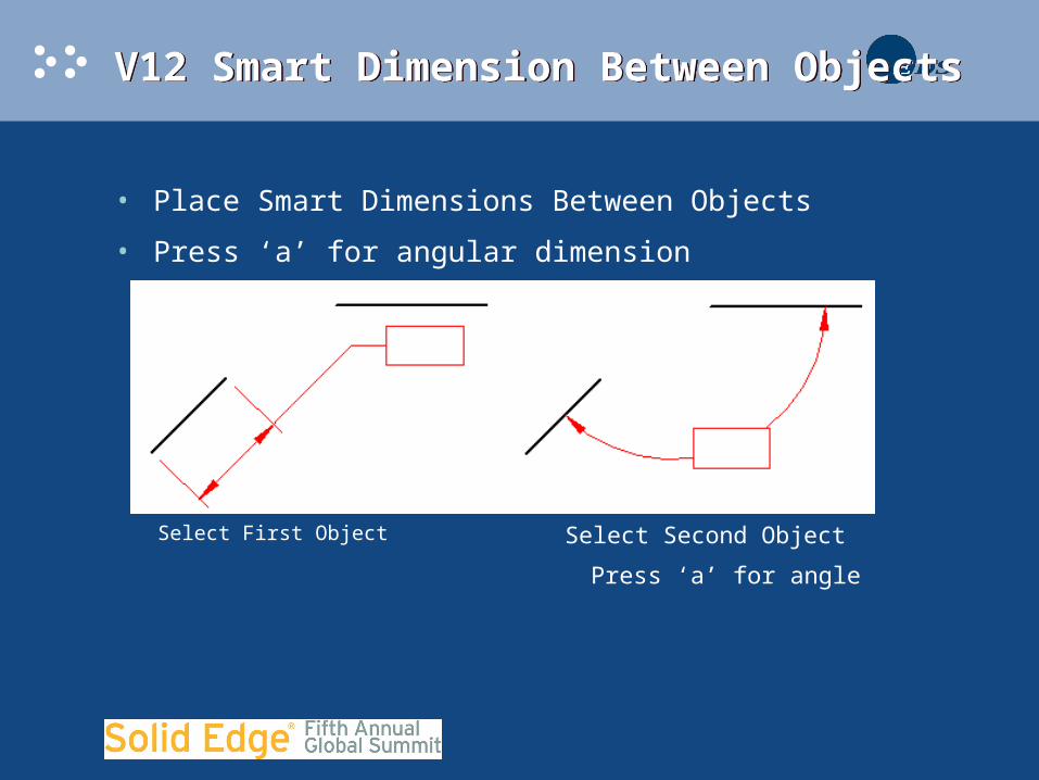
• Place Smart Dimensions Between Objects
• Press ‘a’ for angular dimension
Select First Object Select Second ObjectPress ‘a’ for angle

V12 Smart Dimension Between ObjectsV12 Smart Dimension Between Objects

V14 3D Dimensions on Pictorial ViewsV14 3D Dimensions on Pictorial Views
V14 Zero and Negative DimensionsV14 Zero and Negative Dimensions
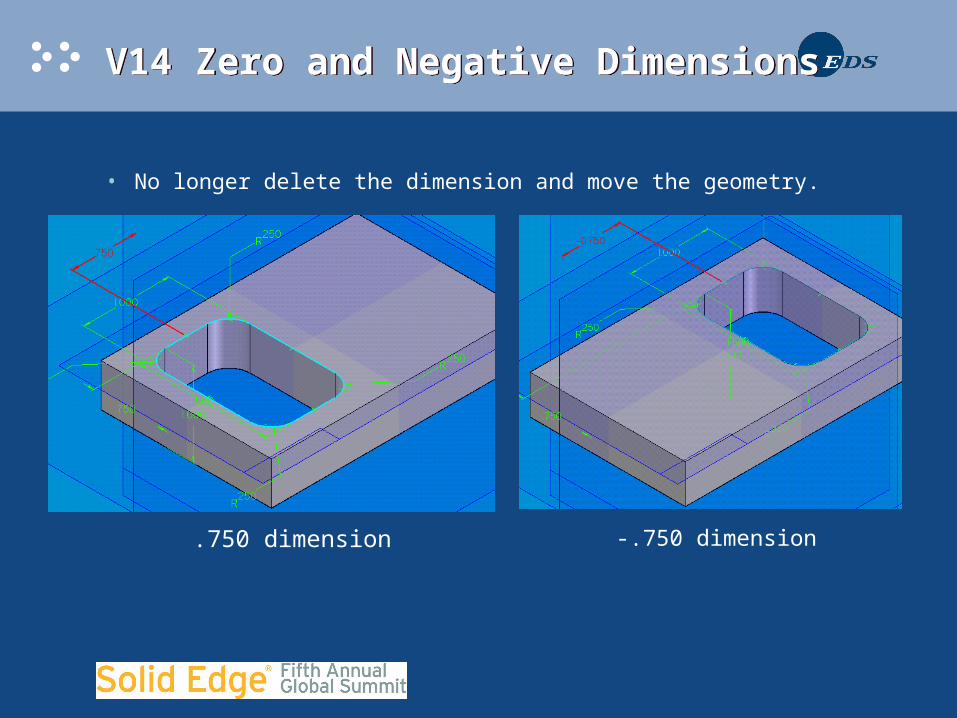
• No longer delete the dimension and move the geometry.
-.750 dimension.750 dimension

V14 Zero and Negative DimensionsV14 Zero and Negative Dimensions
V14 Variable DimensionsV14 Variable Dimensions
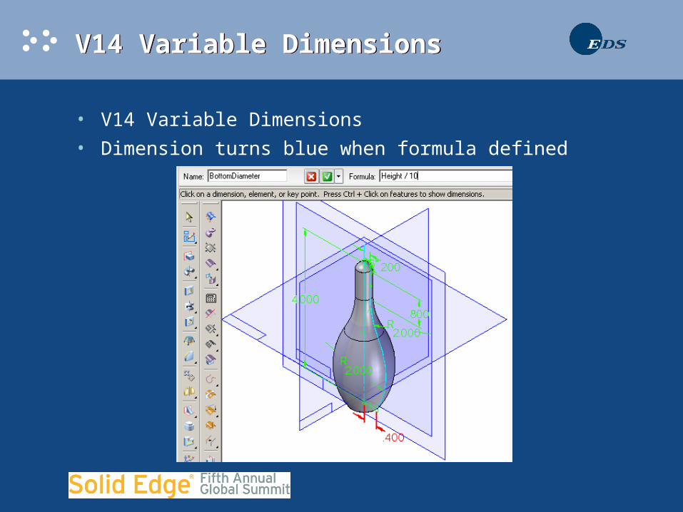
• V14 Variable Dimensions
• Dimension turns blue when formula defined
V14 Variable DimensionsV14 Variable Dimensions
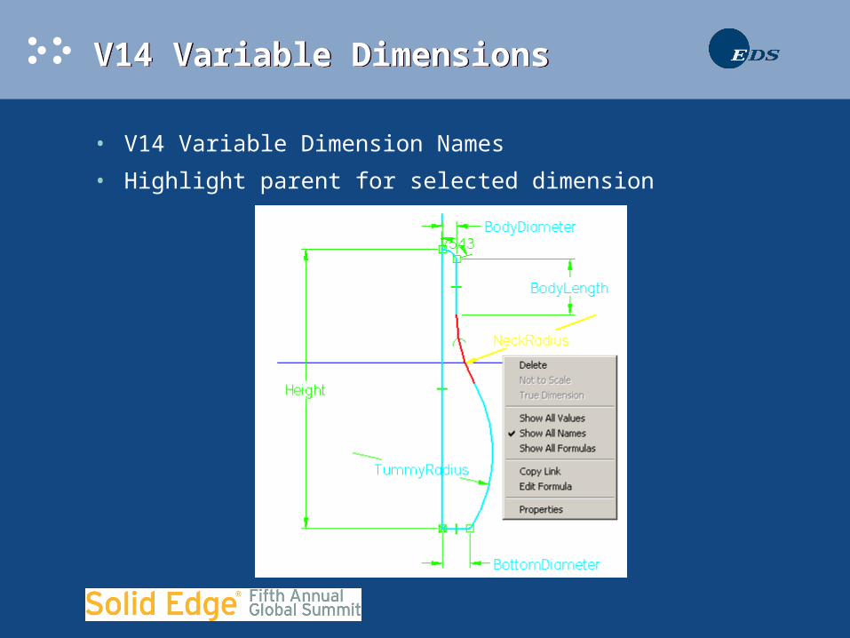
• V14 Variable Dimension Names
• Highlight parent for selected dimension
V14 Variable DimensionsV14 Variable Dimensions
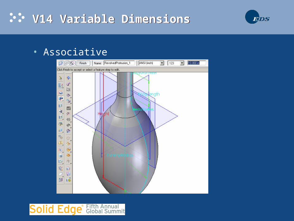
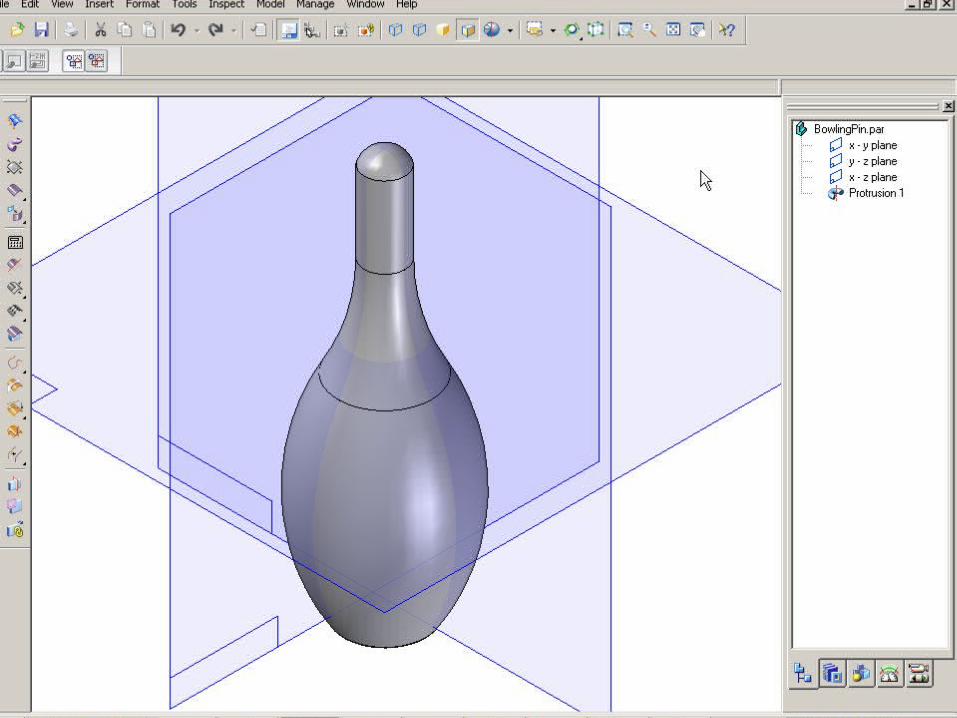
• Associative
V14 Variable DimensionsV14 Variable Dimensions
V14 Double Click AnnotationsV14 Double Click Annotations
• Double Click to Edit Properties
– Callout
– Surface Texture
– Weld Symbol
– Feature Control Frame
• Double Click Cutting Plane Line to Edit
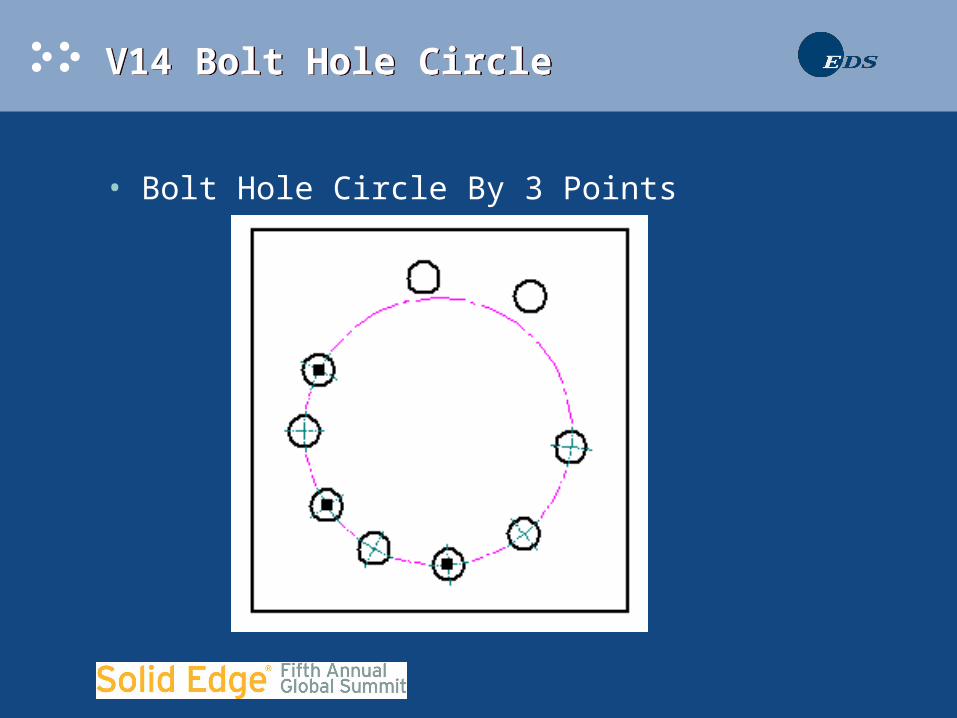
V14 Bolt Hole CircleV14 Bolt Hole Circle
• Bolt Hole Circle By 3 Points
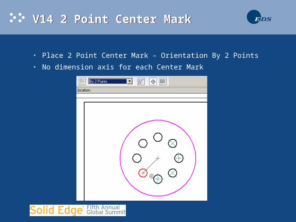
V14 2 Point Center MarkV14 2 Point Center Mark
• Place 2 Point Center Mark – Orientation By 2 Points
• No dimension axis for each Center Mark
Thank You!Thank You!
• Questions?