Embed Size (px)
Citation preview
Extended Modular Multilevel Converters Suitable for Medium-Voltage and Large-Current
STATCOM Applications
H. Mohammadi Pirouz, Student Member, IEEE, M. Tavakoli Bina, Senior Member, IEEE Faculty of Electrical Engineering
K. N. Toosi University of Technology Tehran, Iran
[email protected] and [email protected]
Abstract—This paper discusses a new transformerless shunt static compensator (STATCOM) based on the extended modular multilevel converter (EMMC), to achieve higher performance in a medium-voltage large-current network. It introduces an appropriate control algorithm based on a phase-shifted carrier modulation strategy, to ensure the source-end three-phase currents are sinusoidal and balanced, balancing the voltages of the dc-link capacitors of the modules as well. Compared to the conventional modular multilevel converters (MMC), the EMMC introduces higher reliability and better performance in the distorted large-current systems. Simulation results from a complete model of the proposed STATCOM are presented, confirming the pre-defined objectives. One interesting application for the EMMC-based STATCOM could be the improvement in power quality and performance of the electrified railway power supply systems.
Keywords-modular multilevel converter; unbalance load; medium voltage; larg current
I. INTRODUCTION Nowadays, modern medium-voltage distribution systems
supply non-linear loads such as single-phase AC traction systems. These loads make the network to operate under undesired conditions, i.e. distorted, uncontrolled reactive power and significant unbalance enforcement [1-2]. Therefore, these associated inevitable issues ought to be simultaneously resolved to achieve acceptable power quality level. Meanwhile, mitigation of all these power quality problems by means of a single compensator is a challenging task in a medium-voltage network [3].
However, full-bridge cascaded converter (FBCC) has been established as the most preferred solution for management of reactive power in the distribution systems, and improving power quality in the medium-voltage and high-power industries [4]. The FBCC based STATCOM could be directly connected to a medium-voltage network without the bulky step-up transformer, resulting in cost and weight reduction [3-5]. Unlike diode clamped multilevel converter (DCMC) and flying capacitor clamped multilevel converter (FCMC), the FBCC introduces smaller total losses along with higher reliability [6]. Furthermore, it can implement a high number of levels more easily as compared with the DCMC and FCMC. Meanwhile, it
has some restrictions when operating under distorted unbalance situations in comparison to those of the DCMC and the FCMC [3-8]. Each leg of the FBCC consists of a number of series-connected isolated full-bridge modules, and the three legs can be connected either in delta structure or in star structure. The delta-connected FBCC cannot possibly generate the third-order harmonic or zero component current. On the other hand, the active power cannot be exchanged among the legs, when the star-connected FBCC operates under the unbalanced conditions. This makes the DC voltage balancing for the dc-link capacitors of the modules in three legs almost impossible, when the converter currents are unbalanced [7]. As a result, the FBCC based STATCOM is not a suitable topology to achieve full compensation of three-phase medium-voltage loads, i.e. harmonic elimination, reactive power optimization, and balancing in the three or four-wire networks.
Recently, modular multilevel converter (MMC) was introduced for medium-voltage applications [9-10]. The MMC is comprised of two half-bridge cascaded converters (HBCC), which connected to the network in parallel, without the need for any coupling transformer. Each leg of both HBCC consists of a number of series-connected half-bridge modules, and the legs are connected in star structure. Thanks to the modularity of the MMC, it is increasingly attractive to high-voltage dc transmission (HVDC), flexible ac transmission systems (FACTS), and medium-voltage drives [11]. The main advantage of applying the MMC as a STATCOM is that it could operate under unbalanced and distorted conditions properly, while voltages of the dc-link capacitors remain balanced [8]. Then, the MMC based STATCOM can be controlled for various purposes such as reactive power and unbalance compensation, voltage regulation, and harmonic cancellation in order to achieve full compensation of medium-voltage loads.
The focus of this paper is to realize a new transformerless STATCOM based on two or more parallel MMC, that is called here the extended MMC (EMMC), in order to the full compensation of medium-voltage and large-current (MV-LC) loads, such as electrified railway system. The EMMC produces higher quality current waveforms for the network in comparison to the MMC, reducing the conductive electromagnetic interference concerns in large-current
This work was supported in part by the power quality and reactive power laboratory of E. E. Faculty in K. N. Toosi University of Technology.
978-1-4244-7398-4/10/$26.00 ©2010 IEEE IPEC 2010487
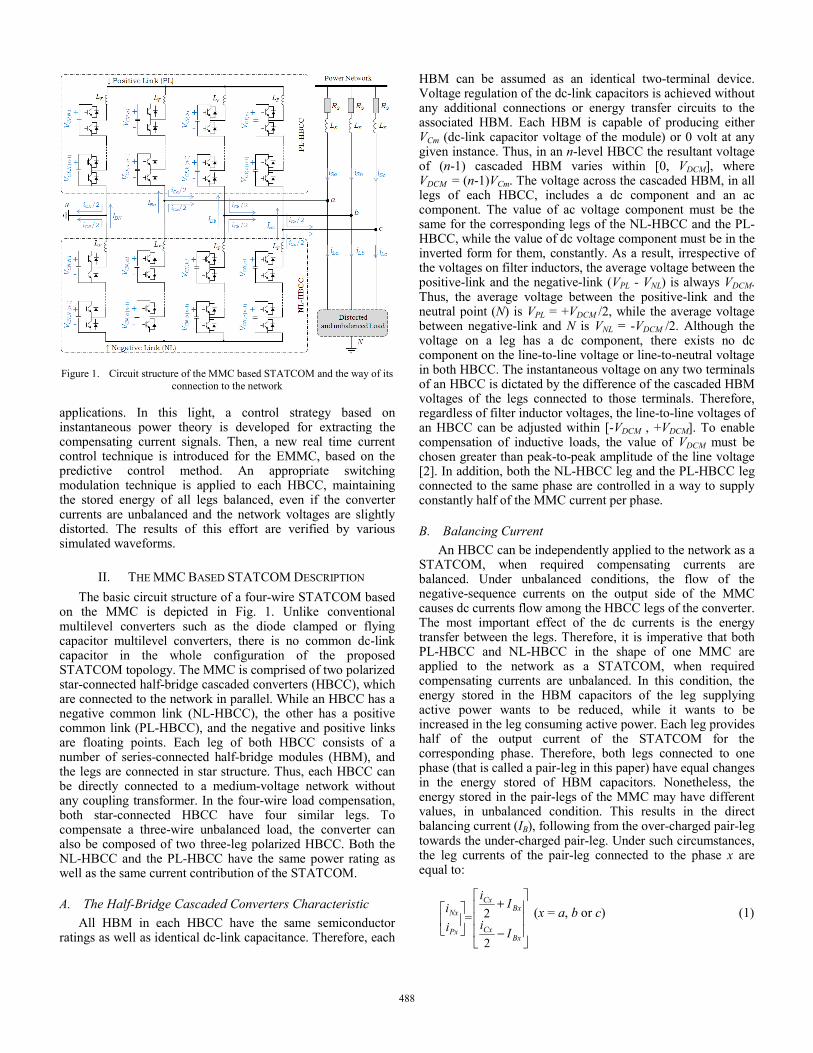
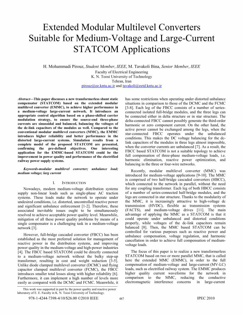
Figure 1. Circuit structure of the MMC based STATCOM and the way of its connection to the network
applications. In this light, a control strategy based on instantaneous power theory is developed for extracting the compensating current signals. Then, a new real time current control technique is introduced for the EMMC, based on the predictive control method. An appropriate switching modulation technique is applied to each HBCC, maintaining the stored energy of all legs balanced, even if the converter currents are unbalanced and the network voltages are slightly distorted. The results of this effort are verified by various simulated waveforms.
II. THE MMC BASED STATCOM DESCRIPTION The basic circuit structure of a four-wire STATCOM based
on the MMC is depicted in Fig. 1. Unlike conventional multilevel converters such as the diode clamped or flying capacitor multilevel converters, there is no common dc-link capacitor in the whole configuration of the proposed STATCOM topology. The MMC is comprised of two polarized star-connected half-bridge cascaded converters (HBCC), which are connected to the network in parallel. While an HBCC has a negative common link (NL-HBCC), the other has a positive common link (PL-HBCC), and the negative and positive links are floating points. Each leg of both HBCC consists of a number of series-connected half-bridge modules (HBM), and the legs are connected in star structure. Thus, each HBCC can be directly connected to a medium-voltage network without any coupling transformer. In the four-wire load compensation, both star-connected HBCC have four similar legs. To compensate a three-wire unbalanced load, the converter can also be composed of two three-leg polarized HBCC. Both the NL-HBCC and the PL-HBCC have the same power rating as well as the same current contribution of the STATCOM.
A. The Half-Bridge Cascaded Converters Characteristic All HBM in each HBCC have the same semiconductor
ratings as well as identical dc-link capacitance. Therefore, each
HBM can be assumed as an identical two-terminal device. Voltage regulation of the dc-link capacitors is achieved without any additional connections or energy transfer circuits to the associated HBM. Each HBM is capable of producing either VCm (dc-link capacitor voltage of the module) or 0 volt at any given instance. Thus, in an n-level HBCC the resultant voltage of (n-1) cascaded HBM varies within [0, VDCM], where VDCM = (n-1)VCm. The voltage across the cascaded HBM, in all legs of each HBCC, includes a dc component and an ac component. The value of ac voltage component must be the same for the corresponding legs of the NL-HBCC and the PL-HBCC, while the value of dc voltage component must be in the inverted form for them, constantly. As a result, irrespective of the voltages on filter inductors, the average voltage between the positive-link and the negative-link (VPL - VNL) is always VDCM. Thus, the average voltage between the positive-link and the neutral point (N) is VPL = +VDCM /2, while the average voltage between negative-link and N is VNL = -VDCM /2. Although the voltage on a leg has a dc component, there exists no dc component on the line-to-line voltage or line-to-neutral voltage in both HBCC. The instantaneous voltage on any two terminals of an HBCC is dictated by the difference of the cascaded HBM voltages of the legs connected to those terminals. Therefore, regardless of filter inductor voltages, the line-to-line voltages of an HBCC can be adjusted within [-VDCM , +VDCM]. To enable compensation of inductive loads, the value of VDCM must be chosen greater than peak-to-peak amplitude of the line voltage [2]. In addition, both the NL-HBCC leg and the PL-HBCC leg connected to the same phase are controlled in a way to supply constantly half of the MMC current per phase.
B. Balancing Current An HBCC can be independently applied to the network as a
STATCOM, when required compensating currents are balanced. Under unbalanced conditions, the flow of the negative-sequence currents on the output side of the MMC causes dc currents flow among the HBCC legs of the converter. The most important effect of the dc currents is the energy transfer between the legs. Therefore, it is imperative that both PL-HBCC and NL-HBCC in the shape of one MMC are applied to the network as a STATCOM, when required compensating currents are unbalanced. In this condition, the energy stored in the HBM capacitors of the leg supplying active power wants to be reduced, while it wants to be increased in the leg consuming active power. Each leg provides half of the output current of the STATCOM for the corresponding phase. Therefore, both legs connected to one phase (that is called a pair-leg in this paper) have equal changes in the energy stored of HBM capacitors. Nonetheless, the energy stored in the pair-legs of the MMC may have different values, in unbalanced condition. This results in the direct balancing current (IB), following from the over-charged pair-leg towards the under-charged pair-leg. Under such circumstances, the leg currents of the pair-leg connected to the phase x are equal to:
2
2⎥⎥⎥
⎦
⎤
⎢⎢⎢
⎣
⎡
−
+⎥⎦
⎤⎢⎣
⎡
BxCx
BxCx
Px
Nx
Ii
Ii
=ii (x = a, b or c) (1)
488
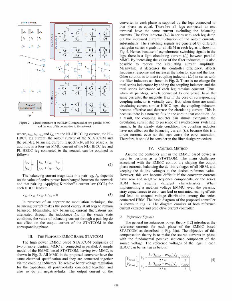
Figure 2. Circuit structure of the EMMC composed of two parallel MMC and the way of its connection to the network.
where, iNx, iPx, iCx and IBx are the NL-HBCC leg current, the PL-HBCC leg current, the output current of the STATCOM and the pair-leg balancing current, respectively, all for phase x. In addition, in a four-leg MMC, current of the NL-HBCC leg and PL-HBCC leg connected to the neutral, can be obtained as follows:
⎥⎦
⎤⎢⎣
⎡++++
−⎥⎦
⎤⎢⎣
⎡
PCPBPA
NCNBNA
PN
NN
iiiiii
=ii
(2)
The balancing current magnitude in a pair-leg, IBx depends on the value of active power interchanged between the network and that pair-leg. Applying Kirchhoff’s current law (KCL) for each HBCC leads to:
IIII BNBCBBBA 0=+++ (3)
In presence of an appropriate modulation technique, the balancing current makes the stored energy at all legs to remain balanced. Meanwhile, any balancing current fluctuations are attenuated through the inductance LF. In the steady state condition, the value of balancing current through a pair-leg do not effect on the output current of the STATCOM in the corresponding phase.
III. THE PROPOSED EMMC BASED STATCOM The high power EMMC based STATCOM comprises of
two or more identical MMC all connected in parallel. A simple model of the EMMC based STATCOM, having two MMC, is shown in Fig. 2. All MMC in the proposed converter have the same electrical specification and they are connected together via the coupling inductors. To achieve better voltage regulation for the capacitors, all positive-links connected together, and also so do all negative-links. The output current of the
converter in each phase is supplied by the legs connected to that phase as equal. Therefore all legs connected to one terminal have the same current excluding the balancing currents. The filter inductor (LF) in series with each leg damp out the increased current fluctuation of the output currents, substantially. The switching signals are generated by different triangular carrier signals for all HBM in each leg as it shown in Fig. 4. Hence, because of asynchronous switching signals in the legs, there is a light circulating current (IC) between parallel MMC. By increasing the value of the filter inductors, it is also possible to reduce the circulating current amplitude. Meanwhile, it decreases the controller efficiency, affects frequency response and increases the inductor size and the loss. Other solution is to insert coupling inductors (LC) in series with the filter inductors as shown in Fig. 2. There is no change for total series inductance by adding the coupling inductor, and the total series inductance of each leg remains constant. Thus, when all pair-legs, which connected to one phase, have the same currents, the magnetic flux in the core of corresponding coupling inductor is virtually zero. But, when there are small circulating current similar HBCC legs, the coupling inductors become effective and decrease the circulating current. This is because there is a nonzero flux in the core in that condition. As a result, the coupling inductor can almost extinguish the circulating current due to presence of asynchronous switching signals. In the steady state condition, the coupling inductor have not affect on the balancing current (IB), because this is a direct current, even so this can cause the core saturation. Therefore, it should be consider in the filter design procedure.
IV. CONTROL METHOD Assume the controller unit in the EMMC based device is
used to perform as a STATCOM. The main challenges associated with the EMMC control are shaping the output phase currents, balancing the dc-link voltages of all HBM, and keeping the dc-link voltages at the desired reference value. However, this can become difficult if the converter currents have zero and negative sequence components, or the series HBM have slightly different characteristics. When implementing a medium voltage EMMC, even the parasitic stray capacitances to earth can lead to unwanted scaling effects and lead to unequal voltage distribution among the series connected HBM. The basic diagram of the proposed controller is shown in Fig. 3. The diagram consists of both reference current extractor and predictive current controller.
A. Reference Signals The general instantaneous power theory [12] introduces the
reference currents for each phase of the EMMC based STATCOM as described in Fig. 3(a). The objective of this compensation theory is to make the source currents in phase with the fundamental positive sequence component of the source voltage. The reference voltages of the legs in each HBCC can be written as below:
⎥⎥⎥⎥
⎦
⎤
⎢⎢⎢⎢
⎣
⎡
−−
−
+−
−⎥⎦
⎤⎢⎣
⎡
2*2).(
2*2).(
,
,
,
,
DCMSCxrefCxFx
DCMSCxrefCxFx
refPx
refNx
Vm
fimiLV
Vm
fimiLV
=VV (4)
489
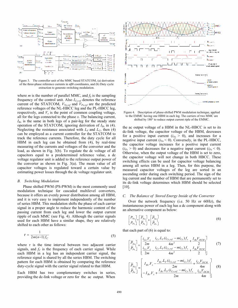
Figure 3. The controller unit of the MMC based STATCOM, (a) derivation of the three-phase reference currents in αβ0 coordinates, and (b) Duty cycle
extraction to generate switching modulation.
where m is the number of parallel MMC, and fS is the sampling frequency of the control unit. Also ICx,ref denotes the reference current of the STATCOM, VNx,ref and VPx,ref are the predicted reference voltages of the NL-HBCC leg and the PL-HBCC leg, respectively, and Vx is the point of common coupling voltage, all for the legs connected to the phase x. The balancing current, IBx is the same in both legs of a pair-leg for the steady state operation of the STATCOM, ignoring derivation of IBx in (4). Neglecting the resistance associated with LF and LC, then (4) can be employed as a current controller for the STATCOM to track the reference currents. Therefore, the duty cycle for all HBM in each leg can be obtained from (4), by real-time measuring of the currents and voltages of the converter and the load, as shown in Fig. 3(b). To regulate the dc voltage of all capacitors equal to a predetermined reference value, a dc voltage regulator unit is added to the reference output power of the converter as shown in Fig. 3(a). The mean value of all capacitor voltages is regulated toward a certain value by estimating power losses through the dc voltage regulator unit.
B. Switching Modulation Phase shifted PWM (PS-PWM) is the most commonly used
modulation technique for cascaded multilevel converters, because it offers an evenly power distribution among all HBM, and it is very easy to implement independently of the number of series HBM. This modulation shifts the phase of each carrier signal in a proper angle to reduce the harmonic content of the passing current from each leg and lower the output current ripple of each MMC (see Fig. 4). Although the carrier signals used for each HBM have a similar shape, they are relatively shifted to each other as follows:
Cfnm )1(21−=τ (5)
where τ is the time interval between two adjacent carrier signals, and fC is the frequency of each carrier signal. While each HBM in a leg has an independent carrier signal, the reference signal is shared by all the series HBM. The switching pattern for each HBM is obtained by comparing the reference duty-cycle signal with the carrier signal related to that HBM.
Each HBM has two complementary switches in series, providing the dc-link voltage or zero for the ac output. When
Figure 4. Description of phase-shifted PWM modulation technique, applied to the EMMC having one HBM in each leg. The carriers of two MMC are
shifted by 180° to reduce output current riple of the EMMC.
the ac output voltage of a HBM in the NL-HBCC is set to its dc-link voltage, the capacitor voltage of the HBM, decreases for a positive input current (iNx > 0), and increases for a negative input current (iNx < 0). Conversely, in the PL-HBCC, the capacitor voltage increases for a positive input current (iPx > 0) and decreases for a negative input current (iPx < 0). Otherwise, when the output voltage of the HBM is set to zero, the capacitor voltage will not change in both HBCC. These switching effects can be used for capacitor voltage balancing among all series HBM in a leg. Then, for this purpose, the measured capacitor voltages of the leg are sorted in an ascending order during each switching period. The sign of the leg current and the number of HBM that are permanently set to its dc-link voltage determines which HBM should be selected [10].
C. The Balance of Stored Energy Inside of the Converter Over the network frequency (i.e. 50 Hz or 60Hz), the
instantaneous power of each leg has a dc component along with an alternative component as below:
⎥⎦
⎤⎢⎣
⎡+⎥
⎦
⎤⎢⎣
⎡⎥⎦
⎤⎢⎣
⎡
Px
Nx
Px
Nx
Px
Nx
PP
PP
=PP
~~
(6)
that each part of (6) is equal to:
⎥⎥⎥⎥
⎦
⎤
⎢⎢⎢⎢
⎣
⎡
+−
−
+−
−=⎥
⎦
⎤⎢⎣
⎡
24)(.
2.
24)(.
2.
2,
2,
DCMBxsCxrefCxFCxxCx
DCMBxsCxrefCxFCxxCx
Px
Nx
VIm
fmiiLimVi
VIm
fmiiLimVi
PP (7)
⎥⎥⎥⎥
⎦
⎤
⎢⎢⎢⎢
⎣
⎡
−−
+−
+−
−=⎥
⎦
⎤⎢⎣
⎡
mVi
mfmiiLI
VI
mVi
mfmiiLI
VI
PP
DCMCxsCxrefCxFBxxBx
DCMCxsCxrefCxFBxxBx
Px
Nx
42)(.
.
42)(.
.~~
,
,
(8)
490
Since both components in (7) are similar, the average active power is the same for both legs of a pair-leg of a MMC, over the network frequency. Moreover, regarding (2), the neutral current of the converter is equally divided between two legs connected to the neutral, in a four-leg MMC. Accordingly, the Instantaneous power for the NL-HBCC leg and PL-HBCC leg connected to the neutral are determinate as follows:
⎥⎥⎥⎥
⎦
⎤
⎢⎢⎢⎢
⎣
⎡
−
⎥⎥⎥⎥
⎦
⎤
⎢⎢⎢⎢
⎣
⎡
−⎥⎦
⎤⎢⎣
⎡
BNDCM
BNDCM
CNDCM
CNDCM
PN
NN
IV
IV
miVm
iV
=PP
2
2
22
22 (9)
Considering (9), the dc component of the instantaneous power is equal to VDCMIBN/2, which is the same for both legs connected to the neutral. As a result, in the theoretical model, the energy stored into both legs of each pair-leg is equal together. On the other hand, the energy stored of all pair-legs becomes equal, due to the presence of balancing currents, resulting energy balance among all pair-leg in the converter. Therefore, each MMC theoretically has the ability of energy balance among all legs in substance, even in unbalance conditions.
V. SIMULATION RESULTS To compare the MMC and the EMMC performance in
STATCOM application, both topologies are simulated and applied to the network, separately. The proposed control algorithm is implemented in the MATLAB, and the power circuit is simulated using the PSIM and then they are linked together using SIMCOUPLER tool of the PSIM. Assuming the electrical railway application, a 25kV network having a distorted unbalanced load is considered to compensation. The load having 18.27% THD is connected between two phases of the PCC. The rate of power for both STATCOM topologies is 2MVA. Each leg of both compensators has 22 HMB. All HBM have a dc storage capacitor with a nominal average dc voltage of 3.3kV. The capacitance of the dc storage capacitor in each HBM is determined on the basis of maximum permitted variations of dc voltage. The switching frequency applied for each HBM is equal to the basic carrier signal frequency (fC). Table I summarizes circuit parameters used for simulation.
As each leg has 22 HMB, the equivalent switching frequency from output current ripple point of view is 22 KHz
TABLE I. CIRCUIT PARAMETERS USED FOR SIMULATION
Parameters Rating
The MMC The EMMC Converter power capacity PCC rms line-to-line voltage Source inductance Source resistance Number of HBM in each leg Number of the MMC Inductance of filter inductor Inductance of coupling inductor DC-Link voltage of each HBM DC-Link capacitance of each HBM Carrier frequency HBM rms current rating
S VLL LS
RS n m LF LC
VCm
C fC
iHBM
2MVA 25kV
200µH 25mΩ
22 1
3mH -
3.3kV 2.35mF 1000Hz
25A
2MVA 25kV
200µH 25mΩ
22 2
1.2mH 500µH 3.3kV 1.1mF
1000Hz 12A
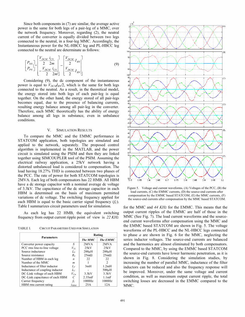
Figure 5. Voltage and current waveforms, (A) Voltages of the PCC, (B) the load currents, (C) the EMMC currents, (D) the source-end currents after
compensation by the EMMC based STATCOM, (E) the MMC currents, (F) the source-end currents after compensation by the MMC based STATCOM.
for the MMC and 44 KHz for the EMMC. This means that the output current ripples of the EMMC are half of those in the MMC (See Fig. 7). The load current waveforms and the source-end current waveforms after compensation using the MMC and the EMMC based STATCOM are shown in Fig. 5. The voltage waveforms of the PL-HBCC and the NL-HBCC legs connected to phase a are shown in Fig. 6 for the MMC, neglecting the series inductor voltages. The source-end currents are balanced and the harmonics are almost eliminated by both compensators. Compared to the MMC, by using the EMMC based STATCOM the source-end currents have lower harmonic penetration, as it is shown in Fig. 8. Considering the simulation studies, by increasing the number of parallel MMC, inductance of the filter inductors can be reduced and also the frequency response will be improved. Moreover, under the same voltage and current condition, as well as maximum output current ripple, the total switching losses are decreased in the EMMC compared to the MMC.
491

Figure 6. Voltage of the PL-HBCC and the NL-HBCC legs connected to
phase a, neglecting the series inductor voltage.
Figure 7. Reduction of the ripple on the output current out of the EMMC,
(A) the current out of the MMC 1, (B) the current out of the MMC 2, (C) the EMMC output current.
VI. CONCLUSIONS The expanded modular multilevel converter, EMMC is the
developed model of conventional MMC suitable for medium-voltage large-current applications. The high-power load compensation in the MV-LC networks using the MMC based STATCOM is usually limited by the available semiconductor technology due to the maximum current ratings, losses, and switching frequency. In order to cope with this kind of requirements, it is easier to extend the total rated power of the MMC based STATCOM by simply adding a new MMC. Thus, it improves the reliability when a MMC fails and, also, reduces the weight and size of the HBM as a basilar part. If one of the MMC fails, the rest still does the compensation, within certain limits. These features are highly desired in the medium-voltage large-current (MV-LC) uninterruptable industry such as electric traction systems. Therefore, these advantages motivate the use of the EMMC as a STATCOM for MV-LC applications.
The proposed controllers for both the MMC and the EMMC can regulate all DC capacitor voltages at a predetermined level while the output currents are unbalanced and distorted. Simulations show proper operation of both converters under unbalanced-distorted conditions.
Figure 8. The source-end current harmonic spectrum for phases a, b, and c
after compensation using the MMC (on the right) and the EMMC (on the left). The vertical axes are ratio of the harmonic component to the fundamental
component in percent.
REFERENCES [1] Pee-Chin Tan, R.E. Morrison, D.G. Holmes, “Voltage form factor
control and reactive power compensation in a 25-kV electrified railway system using a shunt active filter based on voltage detection”, IEEE Transactions on Industry Applications, vol. 39 , no. 2, pp. 575 - 581, 2003
[2] M. Tavakoli Bina, M. D. Panahlou, “Design and installation of a 250 kVAr D-STATCOM for a distribution substation”, Electric Power System Research, pp. 383-391, April 2005
[3] Fang Z. Peng, Jin Wang, “A Universal STATCOM with Delta-Connected Cascade Multilevel Inverter”, 35th Annual IEEE Power Electronics Specialists Conference, Aachen, Gennany, 2004
[4] R.E. Betz, T. Summerst, T. Furney, “Using a Cascaded H-Bridge STATCOM for Rebalancing Unbalanced Voltages”, The 7th International Conference on Power Electronics, Daegu, Korea, 2007
[5] Fang Z. Peng, John Wang, McKeever, Donald J. Adams, “A Power Line Conditioner Using Cascade Multilevel Inverters for Distribution Systems”, IEEE Transactions on Industrial Application, Vol 34, no 6, pp.1293-1298, 1998
[6] C. K. Lee, J.S K. Leung, S.Y R. Hui, H.S.H. Chung, “Circuit-Level Comparison of STATCOM Technologies”, IEEE Transactions on Power Electronics, Vol 18, no 4, pp. 1084-1092, July 2003
[7] R. E. Betz, T. Summers, and T. Furney. “Symmetry compensation using an H-bridge multilevel STATCOM with zero sequence injection”, Industry Applications Conference, 2006
[8] H. Mohammadi Pirouz, M. Tavakoli Bina, “New Transformerless STATCOM Topology for Compensating Unbalanced Medium-Voltage Loads”, 13th European Conference on Power Electronics and Applications, Barcelona, Spain, 2009
[9] R. Marquardt, “Stromrichters chaltungen mitverteilten Energiespeichern”, German Patent DE 10 103 031/24.01.2001, Jan. 24, 2001.
[10] S. Rohner, S. Bernet, M. Hiller, R. Sommer, “Modulation, Losses and Semiconductor Requirements of Modular Multilevel Converters”, IEEE Transactions on Industrial Electronics, IEEE Early Access, 2009
[11] M. Hagiwara, H. Akagi, “Control and Experiment of Pulsewidth-Modulated Modular Multilevel Converters”, IEEE Transactions on Power Electronics, Vol 24 , no 7, pp 1737 - 1746, 2009
[12] H. Akagi, E. H. Watanabe, M. Aredes, “Instantaneous Power Theory and Applications to Power Conditioning”, IEEE press, 2007
492


![[5]the Age of Multilevel Converters Arrives](https://img.pdfslide.us/doc/110x75/553318214a795998578b47e1/5the-age-of-multilevel-converters-arrives.jpg)