Embed Size (px)
Citation preview
Fast Facts Express Timers & Controls
ABB & SSAC Product Lines
Series Index
ABB & SSAC Express Series
Accessories ................................... 38-40ARP .....................................................35BZ1 .....................................................39CM-EFS ...............................................30CM-ENS up/down ...............................36CM-ESS ...............................................29CM-MSS ..............................................36CM-PFS ...............................................28CM-SFS ...............................................34CM-SRS ..............................................33CT-AHD ...............................................20CT-ARS ................................................20CT-ERD ................................................15CT-MFD ......................................... 16-17CT-MVS ......................................... 18-19DLMU ..................................................25
Series Number Page
ECS .....................................................31FA ........................................................37FB ........................................................37FH3P ....................................................37FS126 ..................................................23FS127 ..................................................23FS146 ..................................................23FS155 ..................................................37HLMU ..................................................24HRPS/HRIS ........... QS ..........................7HRPU/HRIU ........... QS ..........................8KRPD ..................... QS ..........................3KRPS ..................... QS ..........................2KSD1 ...................................................21KSD2 ...................................................21KSDB ...................................................21
KSDS ...................................................21KSPD .....................QS ..........................5KSPS .....................QS ..........................4KSPU .....................QS ..........................6LCS ......................................................31LLC5 ....................................................35LLP ......................................................40LPM .....................................................31NDS .....................................................38OT ........................................................38P0XXX- .......................................... 39-40P1XXX- .......................................... 38-39PCR .....................................................37PHST ...................................................40PLMU ..................................................26PSC .....................................................38
RS ..........................QS ........................23SCR .....................................................37TCS ......................................................32TCSA ...................................................32TDB .....................................................14TDI .......................................................14TDM .....................................................14TDR .....................................................15TDS ......................................................14TDU .....................................................22TMV .....................................................22TRDU ............................................. 12-13TRU .....................................................11WVM ....................................................27
Series Number Page Series Number Page Series Number Page
All Part Numbers are unless marked QS ( )
Index
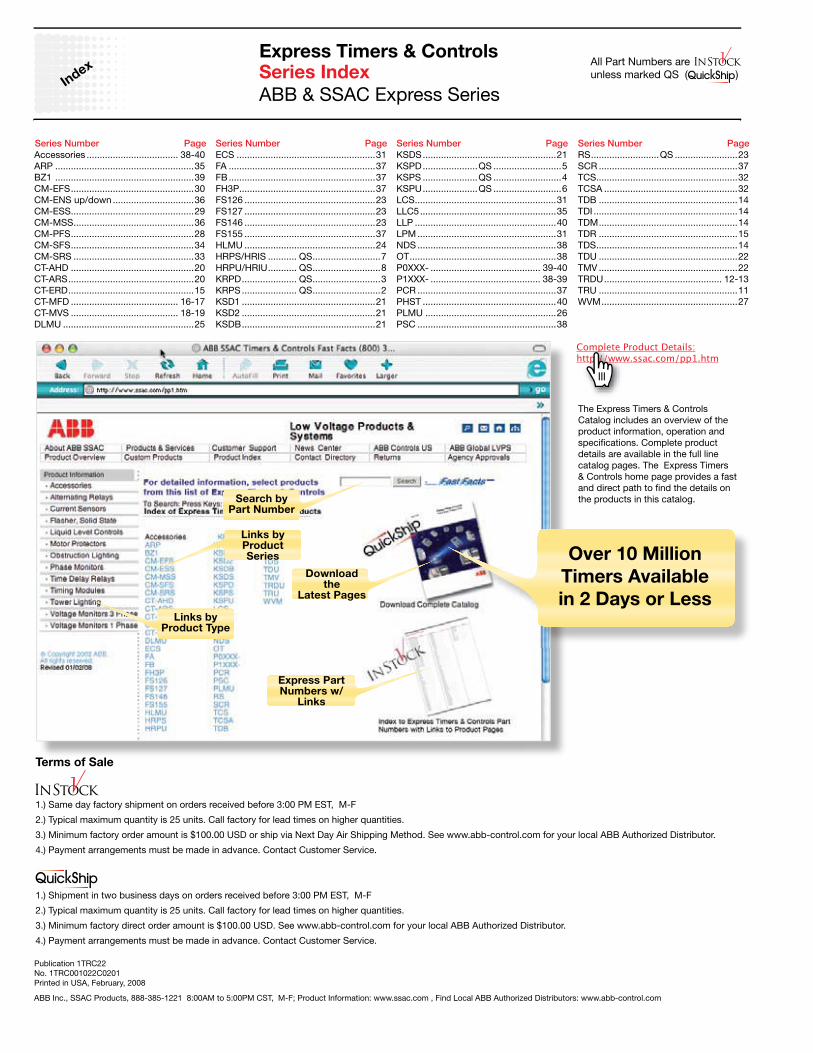
The Express Timers & Controls Catalog includes an overview of the product information, operation and specifications. Complete product details are available in the full line catalog pages. The Express Timers & Controls home page provides a fast and direct path to find the details on the products in this catalog.
Terms of Sale
1.) Same day factory shipment on orders received before 3:00 PM EST, M-F
2.) Typical maximum quantity is 25 units. Call factory for lead times on higher quantities.
3.) Minimum factory order amount is $100.00 USD or ship via Next Day Air Shipping Method. See www.abb-control.com for your local ABB Authorized Distributor.
4.) Payment arrangements must be made in advance. Contact Customer Service.
1.) Shipment in two business days on orders received before 3:00 PM EST, M-F
2.) Typical maximum quantity is 25 units. Call factory for lead times on higher quantities.
3.) Minimum factory direct order amount is $100.00 USD. See www.abb-control.com for your local ABB Authorized Distributor.
4.) Payment arrangements must be made in advance. Contact Customer Service.
ABB Inc., SSAC Products, 888-385-1221 8:00AM to 5:00PM CST, M-F; Product Information: www.ssac.com , Find Local ABB Authorized Distributors: www.abb-control.com
Publication 1TRC22No. 1TRC001022C0201Printed in USA, February, 2008
Links byProduct Type
Express Part Numbers w/
Links
Links byProduct Series
Search byPart Number
Download the
Latest Pages
Over 10 Million
Timers Available
in 2 Days or Less
Express Timers & Controls
Low Voltage Products & Systems
ABB Inc. • Sales Sales & Technical Information 1-888-385-1221 8AM to 5PM CST - Product Information www.ssac.com/pp1.htm
1
1TRC001022C0201
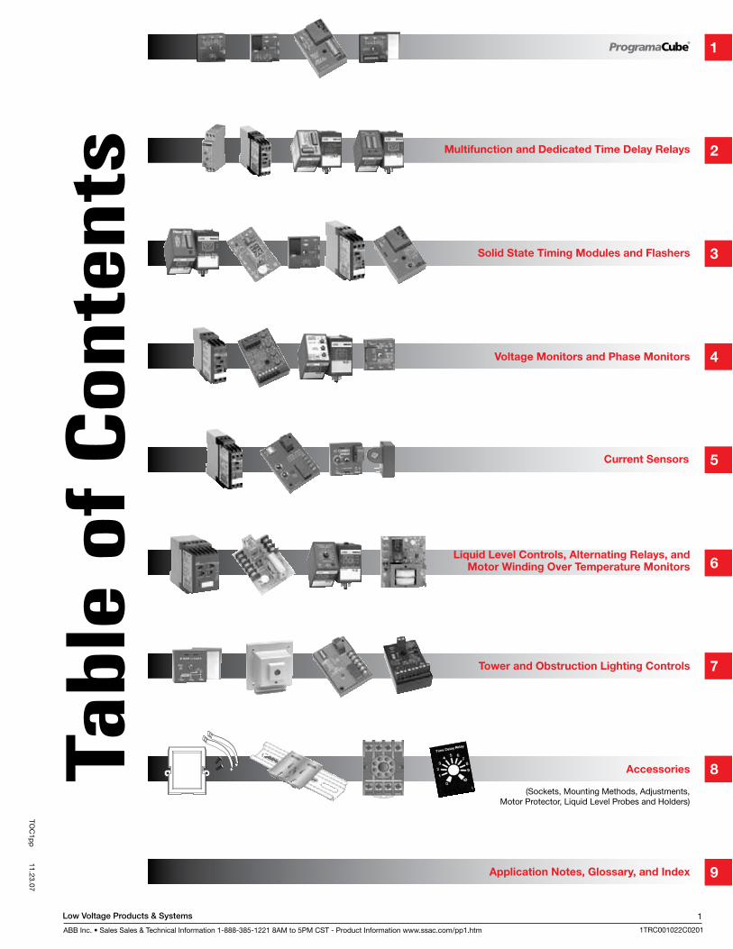
Multifunction and Dedicated Time Delay Relays
Solid State Timing Modules and Flashers
Voltage Monitors and Phase Monitors
Current Sensors
Liquid Level Controls, Alternating Relays, and Motor Winding Over Temperature Monitors
Tower and Obstruction Lighting Controls
Accessories
(Sockets, Mounting Methods, Adjustments, Motor Protector, Liquid Level Probes and Holders)
Application Notes, Glossary, and Index
TOC
1pp
11.23.07
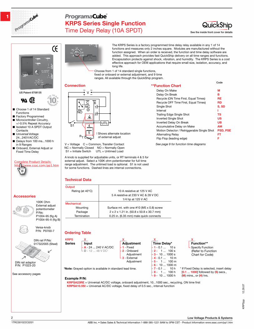
ABB Inc. • Sales Sales & Technical Information 1-888-385-1221 8AM to 5PM CST - Product Information www.ssac.com/pp1.htm
Low Voltage Products & Systems2
1TRC001022C0201
KR
PS
pp
12.
28.0
7
KRPS Series Single Function
Time Delay Relay (10A SPDT)
Choose 1 of 14 Standard Functions
Factory Programmed Microcontroller Circuitry,
+/-0.5% Repeat Accuracy Isolated 10 A SPDT Output
Contacts Universal Voltage
24...240 V AC/DC Delays from 100 ms...1000 h
in 9 Ranges Onboard, External Adjust or
Fixed Time Delay
See accessory pages
DIN rail P/Ns:017322005 (Steel)
DIN rail adaptorP/N: P1023-20
Accessories
Versa-knobP/N: P0700-7
100K OhmExternal adjust potentiometerP/Ns: P1004-95 (fig A)P1004-95-X (fig B)
The KRPS Series is a factory programmed time delay relay available in any 1 of 14 functions and measures only 2 inches square. Modules are manufactured without the function assigned. When an order is received, the function and time delay software are added. This approach provides fast QuickShip delivery on all time ranges and functions. Encapsulation protects against shock, vibration, and humidity. The KRPS Series is a cost effective approach for OEM applications that require small size, isolation, accuracy, and long life.
Connection
A knob is supplied for adjustable units, or RT terminals 4 & 5 for external adjust. Select a 100K ohm potentiometer for full time range adjustment. The untimed load is optional. S1 is not used for some functions. Dashed lines are internal connections.
V = Voltage C = Common, Transfer ContactNC = Normally Closed NO = Normally OpenS1 = Initiate Switch UTL = Untimed Load
! Shows alternate location of external adjust
Delay On Make M
Delay On Break B
Recycle (ON Time First, Equal Times) RE
Recycle OFF Time First, Equal Times) RD
Single Shot S, SD
Interval I
Trailing Edge Single Shot TS
Inverted Single Shot US
Inverted Delay On Break UB
Accumulative Delay on Make AM
Motion Detector / Retriggerable Single Shot PSD, PSE
Alternating Relay FT
Flip Flop (leading edge) F
**Function ChartCode
See page 9 for function time diagrams
– A - 24 ... 240 V AC/DC– D - 12 ... 48 V DC†
Example P/N:
– Specify Function (Refer to Function Chart for Code)
KRPS X X X X
Series Input Adjustment Time Delay* Function**– 1 - 0.1 ... 10 s– 2 - 1 ... 100 s– 3 - 10 ... 1000 s– 4 - 0.1 ... 10 m– 5 - 1 ... 100 m– 6 - 10 ... 1000 m– 7 - 0.1 ... 10 h– 8 - 1 ... 100 h– 9 - 10 ... 1000 h
– 1 - Fixed– 2 - Onboard Adjustment– 3 - External Adjustment
* If Fixed Delay is selected, insert delay [0.1 ... 1000] followed by (S) secs., (M) mins., or (H) hrs.
Ordering Table
†Note: Grayed option is available in standard lead time.
KRPSA23RE = Universal AC/DC voltage, onboard adjustment, 10...1000 sec., recycling, ON time firstKRPSA10.5SI = Universal AC/DC voltage, fixed delay of 0.5 sec., interval function
Output
Rating (at 40°C) 10 A resistive at 125 V AC5 A resistive at 230 V AC & 28 V DC
1/4 hp at 125 V ACMechanical
Mounting Surface mt. with one #10 (M5 x 0.8) screwPackage 2 x 2 x 1.21 in. (50.8 x 50.8 x 30.7 mm)
Termination 0.25 in. (6.35 mm) male quick connects
Technical Data
Choose from 1 of 14 standard single functions, fixed or onboard or external adjustment, and 9 time ranges. All available through the QuickShip program.
See the inside front cover for details
US Patent 6708135
Low Voltage Products & Systems
ABB Inc. • Sales Sales & Technical Information 1-888-385-1221 8AM to 5PM CST - Product Information www.ssac.com/pp1.htm
3
1TRC001022C0201
KR
PD
pp
12.28.07
KRPD Series Dual Function
Time Delay Relay (10A SPDT)
Choose 1 of 12 Standard Dual Functions
Factory Programmed Microcontroller Circuitry,
+/-0.5% Repeat Accuracy Isolated 10 A SPDT
Output Contacts Universal Voltage
24 ... 240 V AC/DC Delays from 100 ms ...1000 h
in 9 Ranges
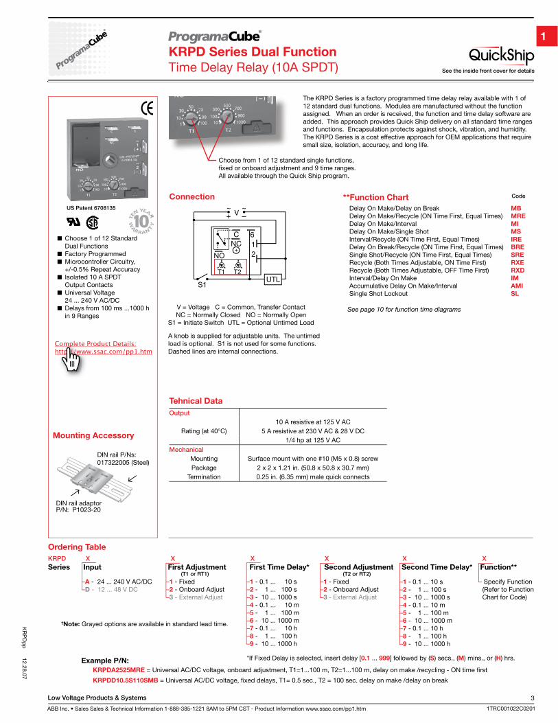
The KRPD Series is a factory programmed time delay relay available with 1 of 12 standard dual functions. Modules are manufactured without the function assigned. When an order is received, the function and time delay software are added. This approach provides Quick Ship delivery on all standard time ranges and functions. Encapsulation protects against shock, vibration, and humidity. The KRPD Series is a cost effective approach for OEM applications that require small size, isolation, accuracy, and long life.
Connection
A knob is supplied for adjustable units. The untimed load is optional. S1 is not used for some functions. Dashed lines are internal connections.
V = Voltage C = Common, Transfer ContactNC = Normally Closed NO = Normally Open
S1 = Initiate Switch UTL = Optional Untimed Load
KRPDA2525MRE = Universal AC/DC voltage, onboard adjustment, T1=1...100 m, T2=1...100 m, delay on make /recycling - ON time first
KRPDD10.5S110SMB = Universal AC/DC voltage, fixed delays, T1= 0.5 sec., T2 = 100 sec. delay on make /delay on break
Example P/N:
–1 - Fixed–2 - Onboard Adjust–3 - External Adjust
– Specify Function (Refer to Function Chart for Code)
–1 - Fixed–2 - Onboard Adjust–3 - External Adjust
–A - 24 ... 240 V AC/DC–D - 12 ... 48 V DC
–1 - 0.1 ... 10 s–2 - 1 ... 100 s–3 - 10 ... 1000 s–4 - 0.1 ... 10 m–5 - 1 ... 100 m–6 - 10 ... 1000 m–7 - 0.1 ... 10 h–8 - 1 ... 100 h–9 - 10 ... 1000 h
–1 - 0.1 ... 10 s–2 - 1 ... 100 s–3 - 10 ... 1000 s–4 - 0.1 ... 10 m–5 - 1 ... 100 m–6 - 10 ... 1000 m–7 - 0.1 ... 10 h–8 - 1 ... 100 h–9 - 10 ... 1000 h
*If Fixed Delay is selected, insert delay [0.1 ... 999] followed by (S) secs., (M) mins., or (H) hrs.
KRPD X X X X X X
Series Input First Adjustment First Time Delay* Second Adjustment Second Time Delay* Function**
†Note: Grayed options are available in standard lead time.
Ordering Table
**Function Chart Code
See page 10 for function time diagrams
Delay On Make/Delay on Break MB
Delay On Make/Recycle (ON Time First, Equal Times) MRE
Delay On Make/Interval MI
Delay On Make/Single Shot MS
Interval/Recycle (ON Time First, Equal Times) IRE
Delay On Break/Recycle (ON Time First, Equal Times) BRE
Single Shot/Recycle (ON Time First, Equal Times) SRE
Recycle (Both Times Adjustable, ON Time First) RXE
Recycle (Both Times Adjustable, OFF Time First) RXD
Interval/Delay On Make IM
Accumulative Delay On Make/Interval AMI
Single Shot Lockout SL
Choose from 1 of 12 standard single functions, fixed or onboard adjustment and 9 time ranges. All available through the Quick Ship program.
DIN rail P/Ns:017322005 (Steel)
DIN rail adaptorP/N: P1023-20
Mounting Accessory
Output
Rating (at 40°C)10 A resistive at 125 V AC
5 A resistive at 230 V AC & 28 V DC1/4 hp at 125 V AC
Mechanical
Mounting Surface mount with one #10 (M5 x 0.8) screwPackage 2 x 2 x 1.21 in. (50.8 x 50.8 x 30.7 mm)
Termination 0.25 in. (6.35 mm) male quick connects
Tehnical Data
See the inside front cover for details
US Patent 6708135
(T1 or RT1) (T2 or RT2)
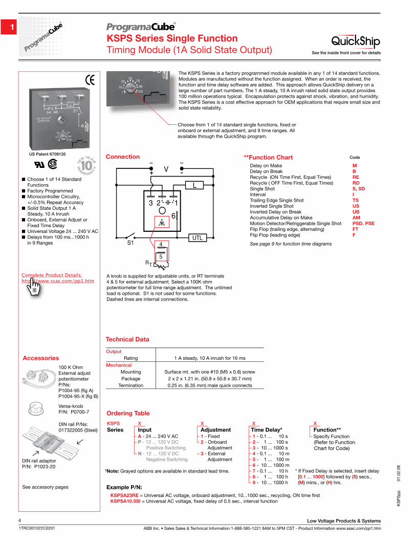
ABB Inc. • Sales Sales & Technical Information 1-888-385-1221 8AM to 5PM CST - Product Information www.ssac.com/pp1.htm
Low Voltage Products & Systems4
1TRC001022C0201
KS
PS
pp
01.
02.0
8
KSPS Series Single Function
Timing Module (1A Solid State Output)
Choose 1 of 14 Standard Functions
Factory Programmed Microcontroller Circuitry,
+/-0.5% Repeat Accuracy Solid State Output 1 A
Steady, 10 A Inrush Onboard, External Adjust or
Fixed Time Delay Universal Voltage 24 ... 240 V AC Delays from 100 ms...1000 h
in 9 Ranges
The KSPS Series is a factory programmed module available in any 1 of 14 standard functions. Modules are manufactured without the function assigned. When an order is received, the function and time delay software are added. This approach allows QuickShip delivery on a large number of part numbers. The 1 A steady, 10 A inrush rated solid state output provides 100 million operations typical. Encapsulation protects against shock, vibration, and humidity. The KSPS Series is a cost effective approach for OEM applications that require small size and solid state reliability.
Accessories
See accessory pages
Versa-knobP/N: P0700-7
100 K Ohm External adjust potentiometerP/Ns: P1004-95 (fig A)P1004-95-X (fig B)
DIN rail P/Ns:017322005 (Steel)
DIN rail adaptorP/N: P1023-20
Connection
A knob is supplied for adjustable units, or RT terminals 4 & 5 for external adjustment. Select a 100K ohm potentiometer for full time range adjustment. The untimed load is optional. S1 is not used for some functions. Dashed lines are internal connections.
– A - 24 ... 240 V AC– P - 12 ... 120 V DC Positive Switching– N - 12 ... 120 V DC Negative Switching
Example P/N:
– Specify Function (Refer to Function Chart for Code)
KSPS X X X X
Series Input Adjustment Time Delay* Function**– 1 - 0.1 ... 10 s– 2 - 1 ... 100 s– 3 - 10 ... 1000 s– 4 - 0.1 ... 10 m– 5 - 1 ... 100 m– 6 - 10 ... 1000 m– 7 - 0.1 ... 10 h– 8 - 1 ... 100 h– 9 - 10 ... 1000 h
– 1 - Fixed– 2 - Onboard Adjustment– 3 - External Adjustment
* If Fixed Delay is selected, insert delay [0.1 ... 1000] followed by (S) secs., (M) mins., or (H) hrs.
Ordering Table
†Note: Grayed options are available in standard lead time.
KSPSA23RE = Universal AC voltage, onboard adjustment, 10...1000 sec., recycling, ON time firstKSPSA10.5SI = Universal AC voltage, fixed delay of 0.5 sec., interval function
**Function Chart
Delay on Make M
Delay on Break B
Recycle (ON Time First, Equal Times) RE
Recycle ( OFF Time First, Equal Times) RD
Single Shot S, SD
Interval I
Trailing Edge Single Shot TS
Inverted Single Shot US
Inverted Delay on Break UB
Accumulative Delay on Make AM
Motion Detector/Retriggerable Single Shot PSD. PSE
Flip Flop (trailing edge, alternating) FT
Flip Flop (leading edge) F
See page 9 for function time diagrams
Code
Choose from 1 of 14 standard single functions, fixed or onboard or external adjustment, and 9 time ranges. All available through the QuickShip program.
Output
Rating 1 A steady, 10 A inrush for 16 msMechanical
Mounting Surface mt. with one #10 (M5 x 0.8) screwPackage 2 x 2 x 1.21 in. (50.8 x 50.8 x 30.7 mm)
Termination 0.25 in. (6.35 mm) male quick connects
Technical Data
See the inside front cover for details
US Patent 6708135
Low Voltage Products & Systems
ABB Inc. • Sales Sales & Technical Information 1-888-385-1221 8AM to 5PM CST - Product Information www.ssac.com/pp1.htm
5
1TRC001022C0201
KS
PD
pp
01.03.08
KSPD Series Dual Function
Timing Module (1A Solid State Output)
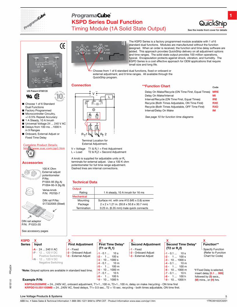
The KSPD Series is a factory programmed module available with 1 of 6 standard dual functions. Modules are manufactured without the function assigned. When an order is received, the function and time delay software are added. This approach provides QuickShip delivery on all adjustment options and time ranges. The solid state output provides 100 million operations, typical. Encapsulation protects against shock, vibration, and humidity. The KSPD Series is a cost effective approach for OEM applications that require small size and long life.
Connection
A knob is supplied for adjustable units or RT terminals for external adjust. Use a 100 K ohm potentiometer for full time range adjustment. Dashed lines are internal connections.
V = Voltage T1 & RT1 = First AdjustmentL = Load T2 & RT2 = Second Adjustment
Terminal Location forExternal Adjustment.
**Function Chart Code
Delay On Make/Recycle (ON Time First, Equal Times) MRE
Delay On Make/Interval MI
Interval/Recycle (ON Time First, Equal Times) IRE
Recycle (Both Times Adjustable, ON Time First) RXE
Recycle (Both Times Adjustable, OFF Time First) RXD
Interval/Delay On Make IM
See page 10 for function time diagrams
Choose from 1 of 6 standard dual functions, fixed or onboard or external adjustment, and 9 time ranges. All available through the QuickShip program.
Output
Rating 1 A steady, 10 A inrush for 16 msMechanical
Mounting Surface mt. with one #10 (M5 x 0.8) screwPackage 2 x 2 x 1.21 in. (50.8 x 50.8 x 30.7 mm)
Termination 0.25 in. (6.35 mm) male quick connects
Technical Data
–1 - 0.1 ... 10 s–2 - 1 ... 100 s–3 - 10 ... 1000 s–4 - 0.1 ... 10 m–5 - 1 ... 100 m–6 - 10 ... 1000 m–7 - 0.1 ... 10 h–8 - 1 ... 100 h–9 - 10 ... 1000 h
–1 - Fixed–2 - Onboard Adjust–3 - External Adjust
–A - 24 ... 240 V AC–P - 12 ... 120 V DC Positive Switching–N - 12 ... 120 V DC Negative Switching
- Specify Function (Refer to Function Chart for Code)
–1 - 0.1 ... 10 s–2 - 1 ... 100 s–3 - 10 ... 1000 s–4 - 0.1 ... 10 m–5 - 1 ... 100 m–6 - 10 ... 1000 m–7 - 0.1 ... 10 h–8 - 1 ... 100 h–9 - 10 ... 1000 h
–1 - Fixed–2 - Onboard Adjust–3 - External Adjust
*If Fixed Delay is selected, insert delay [0.1 ... 999] followed by (S) secs., (M) mins., or (H) hrs.
KSPD X X X X X X
Series Input First Adjustment First Time Delay* Second Adjustment Second Time Delay* Function**
(T1 or RT1) (T2 or R
T2)
Example P/N:
†Note: Grayed options are available in standard lead time.
KSPDA2525MRE = 24...240V AC, onboard adjustment, T1=1...100 m, T2=1...100 m, delay on make /recycling - ON time firstKRPDD10.5S110SMB = 24...240V AC, fixed delays, T1= 0.5 sec., T2 = 15 sec. recycling - both times adjustable, ON time first.
See the inside front cover for details
Accessories
See accessory pages
Versa-knobP/N: P0700-7
100 K OhmExternal adjust potentiometerP/Ns: P1004-95 (fig A)P1004-95-X (fig B)
DIN rail P/Ns:017322005 (Steel)
DIN rail adaptorP/N: P1023-20
US Patent 6708135
Choose 1 of 6 Standard Dual Functions
Factory Programmed Microcontroller Circuitry,
+/-0.5% Repeat Accuracy 1 A Steady, 10 A Inrush Universal Voltage 24 ... 240 V AC Delays from 100 ms ...1000 h
in 9 Ranges Onboard, External Adjust or
Fixed Time Delay
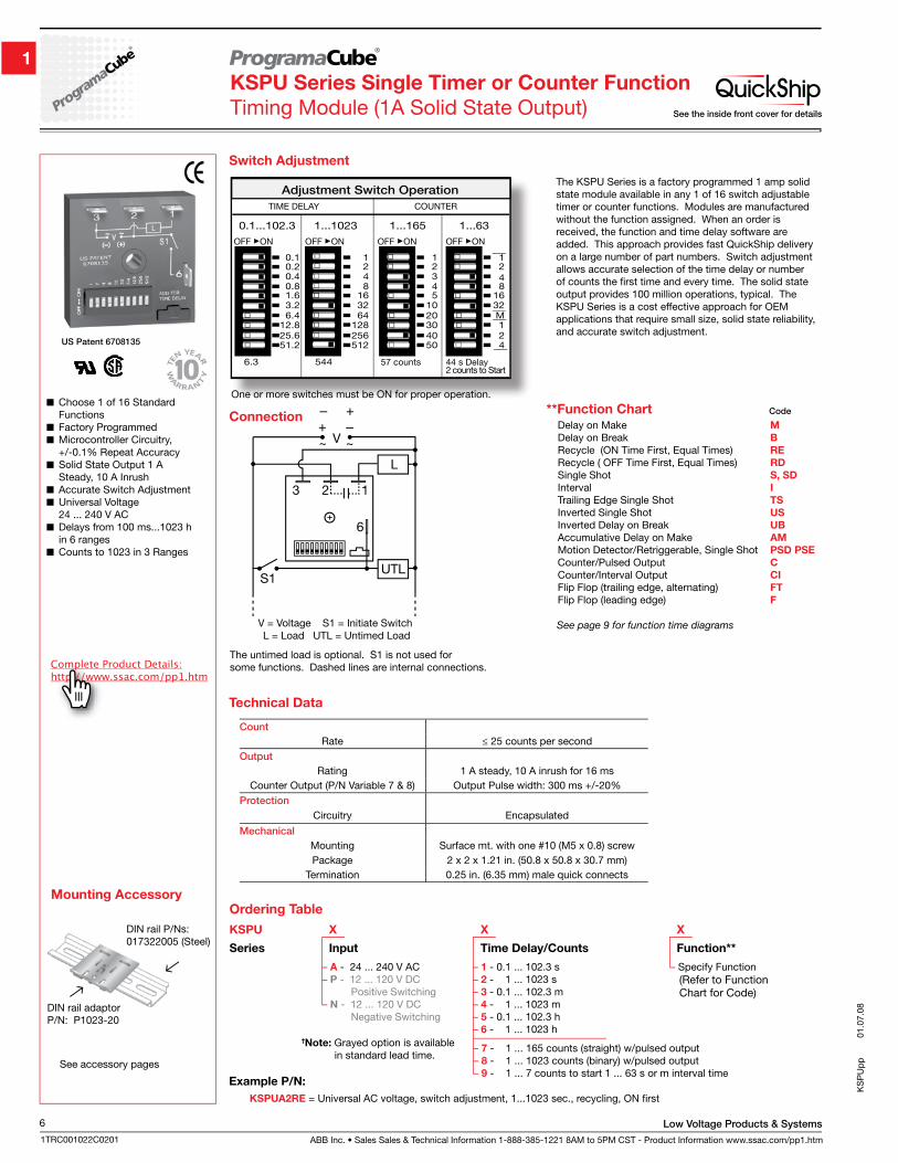
ABB Inc. • Sales Sales & Technical Information 1-888-385-1221 8AM to 5PM CST - Product Information www.ssac.com/pp1.htm
Low Voltage Products & Systems6
1TRC001022C0201
KS
PU
pp
01.
07.0
8
KSPU Series Single Timer or Counter Function
Timing Module (1A Solid State Output)
Choose 1 of 16 Standard Functions
Factory Programmed Microcontroller Circuitry,
+/-0.1% Repeat Accuracy Solid State Output 1 A
Steady, 10 A Inrush Accurate Switch Adjustment Universal Voltage
24 ... 240 V AC Delays from 100 ms...1023 h
in 6 ranges Counts to 1023 in 3 Ranges
Mounting Accessory
See accessory pages
DIN rail P/Ns:017322005 (Steel)
DIN rail adaptorP/N: P1023-20
One or more switches must be ON for proper operation.
Switch Adjustment
Connection
V = Voltage S1 = Initiate Switch L = Load UTL = Untimed Load
The untimed load is optional. S1 is not used for some functions. Dashed lines are internal connections.
Example P/N:
– 1 - 0.1 ... 102.3 s– 2 - 1 ... 1023 s– 3 - 0.1 ... 102.3 m– 4 - 1 ... 1023 m– 5 - 0.1 ... 102.3 h– 6 - 1 ... 1023 h
– Specify Function (Refer to Function Chart for Code)
– A - 24 ... 240 V AC– P - 12 ... 120 V DC Positive Switching– N - 12 ... 120 V DC Negative Switching
KSPUA2RE = Universal AC voltage, switch adjustment, 1...1023 sec., recycling, ON first
– 7 - 1 ... 165 counts (straight) w/pulsed output– 8 - 1 ... 1023 counts (binary) w/pulsed output– 9 - 1 ... 7 counts to start 1 ... 63 s or m interval time
Ordering Table
KSPU X X X
Series Input Time Delay/Counts Function**
†Note: Grayed option is available in standard lead time.
The KSPU Series is a factory programmed 1 amp solid state module available in any 1 of 16 switch adjustable timer or counter functions. Modules are manufactured without the function assigned. When an order is received, the function and time delay software are added. This approach provides fast QuickShip delivery on a large number of part numbers. Switch adjustment allows accurate selection of the time delay or number of counts the first time and every time. The solid state output provides 100 million operations, typical. The KSPU Series is a cost effective approach for OEM applications that require small size, solid state reliability, and accurate switch adjustment.
Count
Rate ≤ 25 counts per secondOutput
Rating 1 A steady, 10 A inrush for 16 msCounter Output (P/N Variable 7 & 8) Output Pulse width: 300 ms +/-20%
Protection
Circuitry Encapsulated
Mechanical
Mounting Surface mt. with one #10 (M5 x 0.8) screwPackage 2 x 2 x 1.21 in. (50.8 x 50.8 x 30.7 mm)
Termination 0.25 in. (6.35 mm) male quick connects
Technical Data
Delay on Make M
Delay on Break B
Recycle (ON Time First, Equal Times) RE
Recycle ( OFF Time First, Equal Times) RD
Single Shot S, SD
Interval I
Trailing Edge Single Shot TS
Inverted Single Shot US
Inverted Delay on Break UB
Accumulative Delay on Make AM
Motion Detector/Retriggerable, Single Shot PSD PSE
Counter/Pulsed Output C
Counter/Interval Output CI
Flip Flop (trailing edge, alternating) FT
Flip Flop (leading edge) F
Code**Function Chart
See page 9 for function time diagrams
See the inside front cover for details
US Patent 6708135
Low Voltage Products & Systems
ABB Inc. • Sales Sales & Technical Information 1-888-385-1221 8AM to 5PM CST - Product Information www.ssac.com/pp1.htm
7
1TRC001022C0201
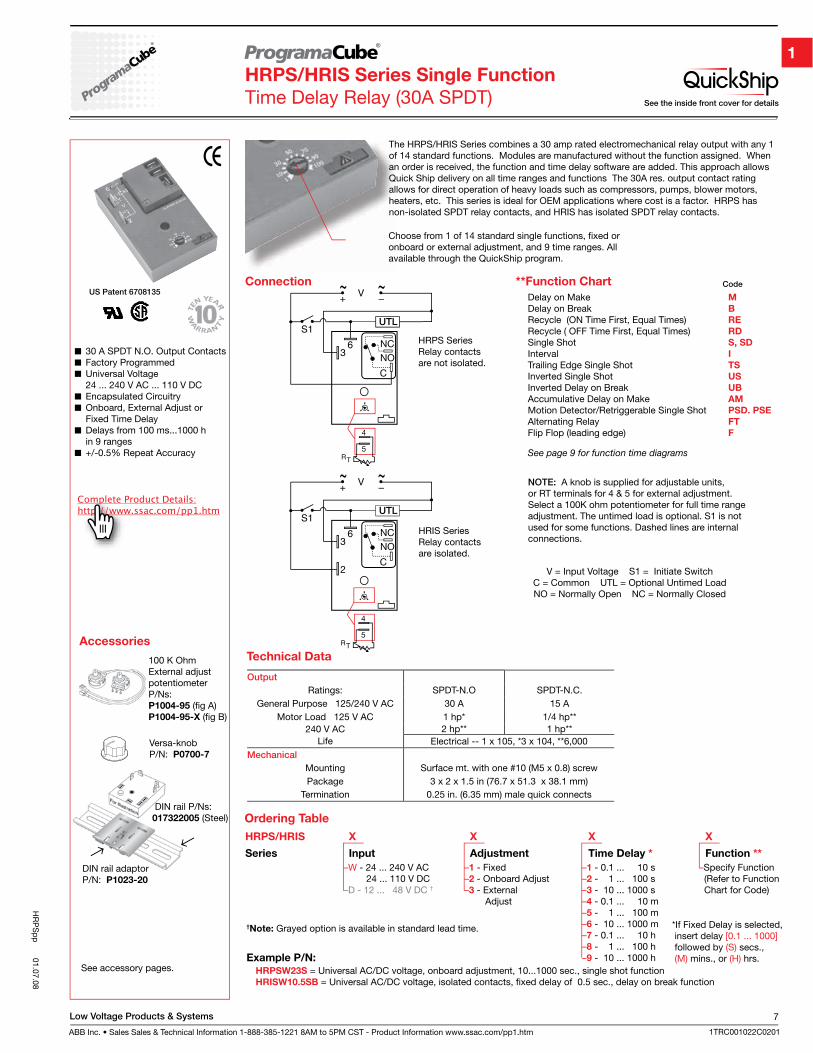
Connection
HRPS SeriesRelay contactsare not isolated.
HRIS SeriesRelay contactsare isolated.
NOTE: A knob is supplied for adjustable units, or RT terminals for 4 & 5 for external adjustment. Select a 100K ohm potentiometer for full time range adjustment. The untimed load is optional. S1 is not used for some functions. Dashed lines are internal connections.
V = Input Voltage S1 = Initiate SwitchC = Common UTL = Optional Untimed Load NO = Normally Open NC = Normally Closed
HR
PS
pp
01.07.08
HRPS/HRIS Series Single Function
Time Delay Relay (30A SPDT)
**Function Chart
Delay on Make M
Delay on Break B
Recycle (ON Time First, Equal Times) RE
Recycle ( OFF Time First, Equal Times) RD
Single Shot S, SD
Interval I
Trailing Edge Single Shot TS
Inverted Single Shot US
Inverted Delay on Break UB
Accumulative Delay on Make AM
Motion Detector/Retriggerable Single Shot PSD. PSE
Alternating Relay FT
Flip Flop (leading edge) F
See page 9 for function time diagrams
Code
30 A SPDT N.O. Output Contacts Factory Programmed Universal Voltage
24 ... 240 V AC ... 110 V DC Encapsulated Circuitry Onboard, External Adjust or
Fixed Time Delay Delays from 100 ms...1000 h
in 9 ranges +/-0.5% Repeat Accuracy
DIN rail adaptorP/N: P1023-20
DIN rail P/Ns: 017322005 (Steel)
Accessories
See accessory pages.
100 K OhmExternal adjustpotentiometerP/Ns: P1004-95 (fig A)P1004-95-X (fig B)
Versa-knobP/N: P0700-7
The HRPS/HRIS Series combines a 30 amp rated electromechanical relay output with any 1 of 14 standard functions. Modules are manufactured without the function assigned. When an order is received, the function and time delay software are added. This approach allows Quick Ship delivery on all time ranges and functions The 30A res. output contact rating allows for direct operation of heavy loads such as compressors, pumps, blower motors, heaters, etc. This series is ideal for OEM applications where cost is a factor. HRPS has non-isolated SPDT relay contacts, and HRIS has isolated SPDT relay contacts.
–1 - 0.1 ... 10 s–2 - 1 ... 100 s–3 - 10 ... 1000 s–4 - 0.1 ... 10 m–5 - 1 ... 100 m–6 - 10 ... 1000 m–7 - 0.1 ... 10 h–8 - 1 ... 100 h–9 - 10 ... 1000 h
–1 - Fixed–2 - Onboard Adjust –3 - External Adjust
HRPS/HRIS X X X X
Series Input Adjustment Time Delay * Function **
–W - 24 ... 240 V AC 24 ... 110 V DC–D - 12 ... 48 V DC †
Ordering Table
–Specify Function (Refer to Function Chart for Code)
*If Fixed Delay is selected, insert delay [0.1 ... 1000] followed by (S) secs., (M) mins., or (H) hrs.Example P/N:
†Note: Grayed option is available in standard lead time.
HRPSW23S = Universal AC/DC voltage, onboard adjustment, 10...1000 sec., single shot functionHRISW10.5SB = Universal AC/DC voltage, isolated contacts, fixed delay of 0.5 sec., delay on break function
Technical Data
Output
Ratings: SPDT-N.O SPDT-N.C.General Purpose 125/240 V AC 30 A 15 A
Motor Load 125 V AC 1 hp* 1/4 hp**240 V AC 2 hp** 1 hp**
Life Electrical -- 1 x 10⁵, *3 x 10⁴, **6,000Mechanical
Mounting Surface mt. with one #10 (M5 x 0.8) screwPackage 3 x 2 x 1.5 in (76.7 x 51.3 x 38.1 mm)
Termination 0.25 in. (6.35 mm) male quick connects
Choose from 1 of 14 standard single functions, fixed or onboard or external adjustment, and 9 time ranges. All available through the QuickShip program.
See the inside front cover for details
US Patent 6708135
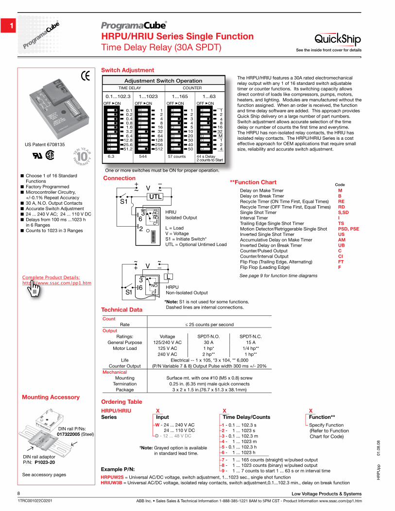
ABB Inc. • Sales Sales & Technical Information 1-888-385-1221 8AM to 5PM CST - Product Information www.ssac.com/pp1.htm
Low Voltage Products & Systems8
1TRC001022C0201
HR
PU
pp
01.
08.0
8
HRPU/HRIU Series Single Function
Time Delay Relay (30A SPDT)
DIN rail adaptorP/N: P1023-20
DIN rail P/Ns: 017322005 (Steel)
See accessory pages
Switch Adjustment
One or more switches must be ON for proper operation.
The HRPU/HRIU features a 30A rated electromechanical relay output with any 1 of 16 standard switch adjustable timer or counter functions. Its switching capacity allows direct control of loads like compressors, pumps, motors, heaters, and lighting. Modules are manufactured without the function assigned. When an order is received, the function and time delay software are added. This approach provides Quick Ship delivery on a large number of part numbers. Switch adjustment allows accurate selection of the time delay or number of counts the first time and everytime. The HRPU has non-isolated relay contacts, the HRIU has isolated relay contacts. The HRPU/HRIU Series is a cost effective approach for OEM applications that require small size, reliability and accurate switch adjustment.
Choose 1 of 16 Standard Functions
Factory Programmed Microcontroller Circuitry,
+/-0.1% Repeat Accuracy 30 A, N.O. Output Contacts Accurate Switch Adjustment 24 ... 240 V AC; 24 ... 110 V DC Delays from 100 ms ...1023 h
in 6 Ranges Counts to 1023 in 3 Ranges
Connection
HRIUIsolated Output
HRPUNon-Isolated Output
L = Load V = VoltageS1 = Initiate Switch*UTL = Optional Untimed Load
Count
Rate ≤ 25 counts per secondOutput
Ratings: Voltage SPDT-N.O. SPDT-N.C. General Purpose 125/240 V AC 30 A 15 A
Motor Load 125 V AC 1 hp* 1/4 hp**240 V AC 2 hp** 1 hp**
Life Electrical -- 1 x 10⁵, *3 x 10⁴, ** 6,000Counter Output (P/N Variable 7 & 8) Output Pulse width 300 ms +/- 20%
Mechanical
Mounting Surface mt. with one #10 (M5 x 0.8) screwTermination 0.25 in. (6.35 mm) male quick connects
Package 3 x 2 x 1.5 in.(76.7 x 51.3 x 38.1mm)
Technical Data
Code
Delay on Make Timer M
Delay on Break Timer B
Recycle Timer (ON Time First, Equal Times) RE
Recycle Timer (OFF Time First, Equal Times) RD
Single Shot Timer S,SD
Interval Timer I
Trailing Edge Single Shot Timer TS
Motion Detector/Retriggerable Single Shot PSD, PSE
Inverted Single Shot Timer US
Accumulative Delay on Make Timer AM
Inverted Delay on Break Timer UB
Counter/Pulsed Output C
Counter/Interval Output CI
Flip Flop (Trailing Edge, Alternating) FT
Flip Flop (Leading Edge) F
**Function Chart
See page 9 for function time diagrams
–W - 24 ... 240 V AC 24 ... 110 V DC–D - 12 ... 48 V DC
–1 - 0.1 ... 102.3 s–2 - 1 ... 1023 s–3 - 0.1 ... 102.3 m–4 - 1 ... 1023 m–5 - 0.1 ... 102.3 h–6 - 1 ... 1023 h
–7 - 1 ... 165 counts (straight) w/pulsed output–8 - 1 ... 1023 counts (binary) w/pulsed output–9 - 1 ... 7 counts to start 1 ... 63 s or m interval time
– Specify Function (Refer to Function Chart for Code)
HRPU/HRIU X X X
Series Input Time Delay/Counts Function**
HRPUW2S = Universal AC/DC voltage, switch adjustment, 1...1023 sec., single shot functionHRIUW3B = Universal AC/DC voltage, isolated relay contacts, switch adjustment,0.1...102.3 min., delay on break function
†Note: Grayed option is available in standard lead time.
US Patent 6708135
Ordering Table
See the inside front cover for details
Mounting Accessory
Example P/N:
*Note: S1 is not used for some functions. Dashed lines are internal connections.
Low Voltage Products & Systems
ABB Inc. • Sales Sales & Technical Information 1-888-385-1221 8AM to 5PM CST - Product Information www.ssac.com/pp1.htm
9
1TRC001022C0201
KR
PS
pp
01.04.08
Delay On MakeM
Delay On BreakB
Recycling (ON First)RE
Single ShotS
Motion DetectorRetriggerable Single ShotPSD
Accumulative Delay On MakeAM
Alternating RelayFT
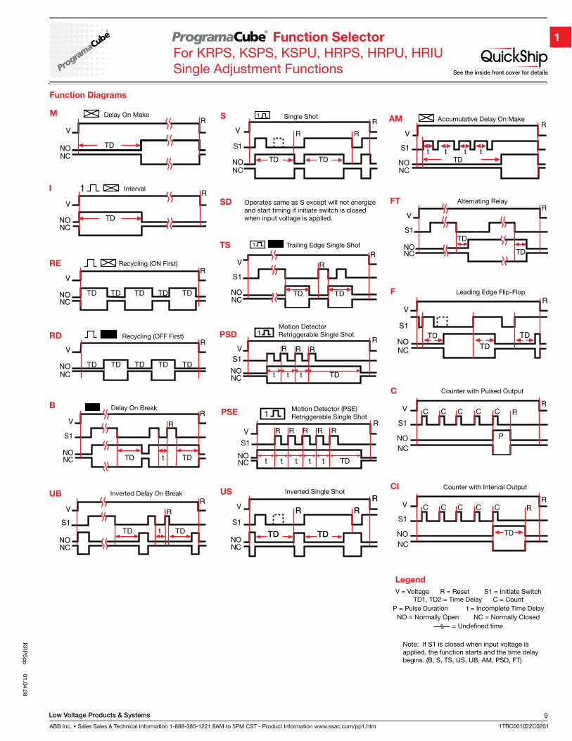
Function Diagrams
Recycling (OFF First)RD
IntervalI
Trailing Edge Single ShotTS
Note: If S1 is closed when input voltage is applied, the function starts and the time delay begins. (B, S, TS, US, UB, AM, PSD, FT)
US Inverted Single ShotInverted Delay On BreakUB
SD Operates same as S except will not energize and start timing if initiate switch is closed when input voltage is applied.
Legend
V = Voltage R = Reset S1 = Initiate SwitchTD1, TD2 = Time Delay C = Count
P = Pulse Duration t = Incomplete Time DelayNO = Normally Open NC = Normally Closed
= Undefined time
Function Selector
For KRPS, KSPS, KSPU, HRPS, HRPU, HRIUSingle Adjustment Functions
Motion Detector (PSE)Retriggerable Single Shot
Leading Edge Flip-Flop F
Counter with Pulsed OutputC
Counter with Interval OutputCI
See the inside front cover for details
PSE
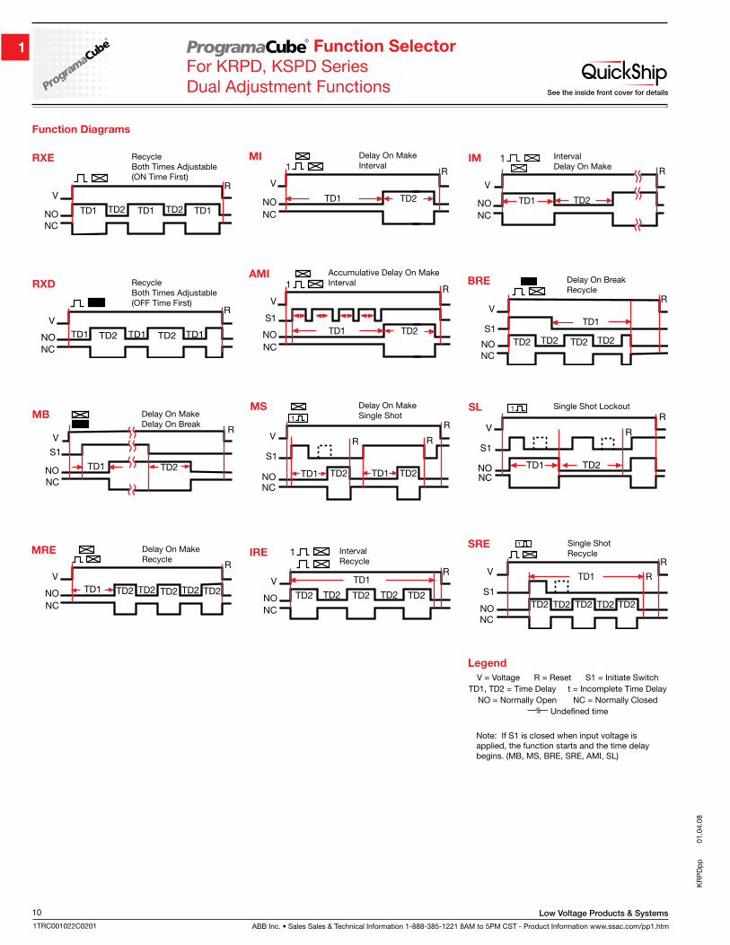
ABB Inc. • Sales Sales & Technical Information 1-888-385-1221 8AM to 5PM CST - Product Information www.ssac.com/pp1.htm
Low Voltage Products & Systems10
1TRC001022C0201
KR
PD
pp
01.
04.0
8
Function Selector
For KRPD, KSPD SeriesDual Adjustment Functions
Function Diagrams
Delay On MakeDelay On Break
MB
Delay On MakeRecycle
MRE
Delay On MakeInterval
MI
IntervalRecycle
IRE
IntervalDelay On Make
IM
Accumulative Delay On MakeInterval
AMI
SL Single Shot LockoutDelay On MakeSingle Shot
MS
Note: If S1 is closed when input voltage is applied, the function starts and the time delay begins. (MB, MS, BRE, SRE, AMI, SL)
Delay On BreakRecycle
BRE
Single ShotRecycle
SRE
Recycle Both Times Adjustable (ON Time First)
RXE
Recycle Both Times Adjustable (OFF Time First)
RXD
Legend
V = Voltage R = Reset S1 = Initiate SwitchTD1, TD2 = Time Delay t = Incomplete Time Delay
NO = Normally Open NC = Normally Closed Undefined time
See the inside front cover for details
Low Voltage Products & Systems
ABB Inc. • Sales Sales & Technical Information 1-888-385-1221 8AM to 5PM CST - Product Information www.ssac.com/pp1.htm
11
1TRC001022C0201
Multi
functio
n
timers
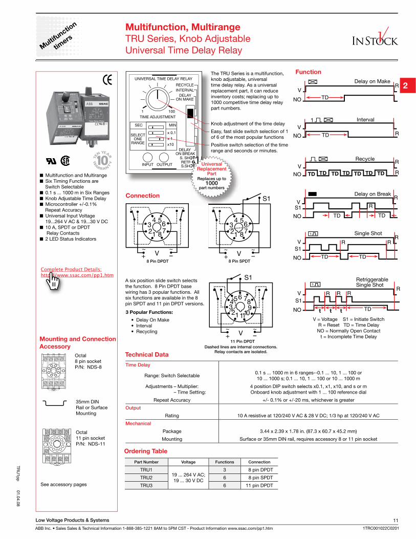
Multifunction, Multirange
TRU Series, Knob AdjustableUniversal Time Delay Relay
Multifunction and Multirange Six Timing Functions are
Switch Selectable 0.1 s ... 1000 m in Six Ranges Knob Adjustable Time Delay Microcontroller +/-0.1%
Repeat Accuracy Universal Input Voltage
19...264 V AC & 19...30 V DC 10 A, SPDT or DPDT
Relay Contacts 2 LED Status Indicators
See accessory pages
Octal8 pin socketP/N: NDS-8
Function
V = Voltage S1 = Initiate SwitchR = Reset TD = Time DelayNO = Normally Open Contact
t = Incomplete Time Delay
Connection
3 Popular Functions:
• Delay On Make • Interval • Recycling
11 Pin DPDT
Dashed lines are internal connections.Relay contacts are isolated.
8 Pin SPDT 8 Pin DPDT
The TRU Series is a multifunction, knob adjustable, universal time delay relay. As a universal replacement part, it can reduce inventory costs; replacing up to 1000 competitive time delay relay part numbers.
Knob adjustment of the time delay
Easy, fast slide switch selection of 1 of 6 of the most popular functions
Positive switch selection of the time range and seconds or minutes.
Time Delay
Range: Switch Selectable0.1 s ... 1000 m in 6 ranges--0.1 ... 10, 1 ... 100 or 10 ... 1000 s; 0.1 ... 10, 1 ... 100 or 10 ... 1000 m
Adjustments – Multiplier: – Time Setting:
4 position DIP switch selects x0.1, x1, x10, and s or mOnboard knob adjustment with 1 ... 100 reference dial
Repeat Accuracy +/- 0.1% or +/-20 ms, whichever is greater
Output
Rating 10 A resistive at 120/240 V AC & 28 V DC; 1/3 hp at 120/240 V AC
Mechanical
Package 3.44 x 2.39 x 1.78 in. (87.3 x 60.7 x 45.2 mm)
Mounting Surface or 35mm DIN rail, requires accessory 8 or 11 pin socket
Mounting and Connection
Accessory
Part Number Voltage Functions Connection
TRU1 19 ... 264 V AC; 19 ... 30 V DC
3 8 pin DPDT
TRU2 6 8 pin SPDT
TRU3 6 11 pin DPDT
Technical Data
Ordering Table
TRU
1pp
01.04.08
Octal 11 pin socketP/N: NDS-11
35mm DIN Rail or Surface Mounting
A six position slide switch selects the function. 8 Pin DPDT base wiring has 3 popular functions. All six functions are available in the 8 pin SPDT and 11 pin DPDT versions.
UniversalReplacement
PartReplaces up to
1000part numbers
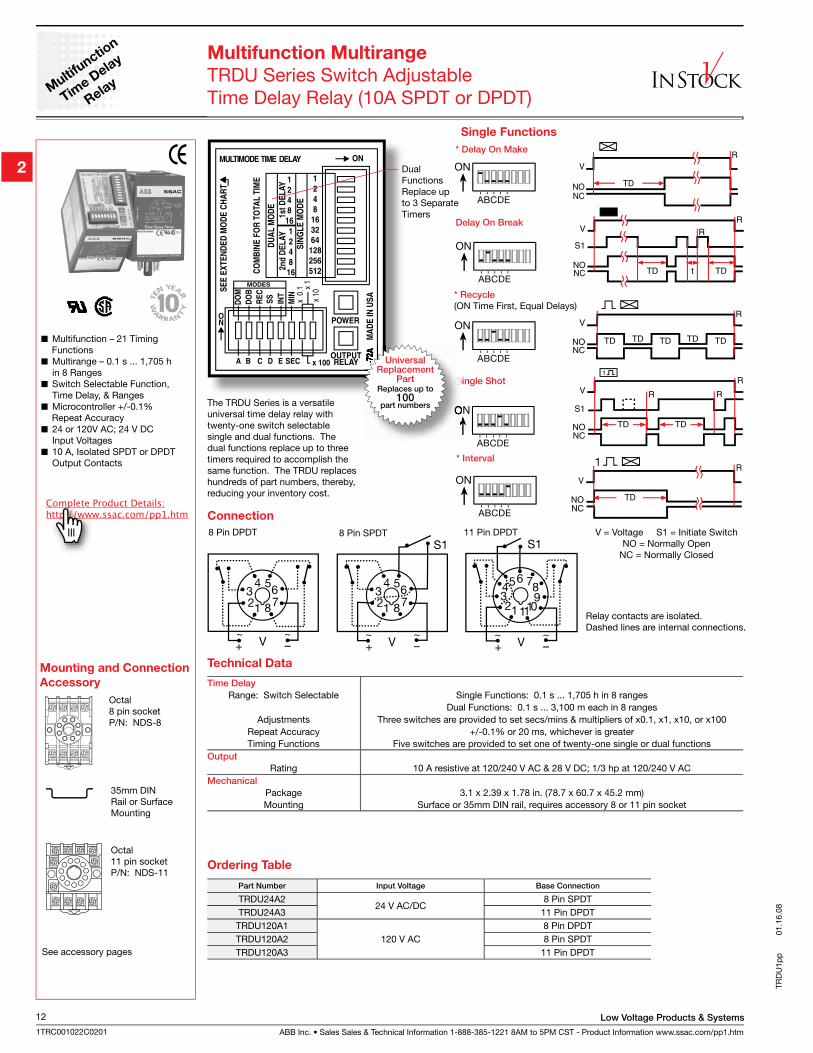
ABB Inc. • Sales Sales & Technical Information 1-888-385-1221 8AM to 5PM CST - Product Information www.ssac.com/pp1.htm
Low Voltage Products & Systems12
1TRC001022C0201
ON
A B C D E
ON
A B C D E
ON
A B C D E
ON
A B C D E
A B C D E
ON
Single Functions
* Delay On Make
Delay On Break
* Recycle
(ON Time First, Equal Delays)
Single Shot
* Interval
Multifunction – 21 Timing Functions
Multirange – 0.1 s ... 1,705 h in 8 Ranges
Switch Selectable Function, Time Delay, & Ranges
Microcontroller +/-0.1% Repeat Accuracy
24 or 120V AC; 24 V DC Input Voltages
10 A, Isolated SPDT or DPDT Output Contacts
Connection
V = Voltage S1 = Initiate SwitchNO = Normally Open
NC = Normally Closed
8 Pin DPDT 11 Pin DPDT
Relay contacts are isolated. Dashed lines are internal connections.
Multifunction Multirange
TRDU Series Switch AdjustableTime Delay Relay (10A SPDT or DPDT)
The TRDU Series is a versatile universal time delay relay with twenty-one switch selectable single and dual functions. The dual functions replace up to three timers required to accomplish the same function. The TRDU replaces hundreds of part numbers, thereby, reducing your inventory cost.
Time Delay
Range: Switch Selectable Single Functions: 0.1 s ... 1,705 h in 8 rangesDual Functions: 0.1 s ... 3,100 m each in 8 ranges
Adjustments Three switches are provided to set secs/mins & multipliers of x0.1, x1, x10, or x100Repeat Accuracy +/-0.1% or 20 ms, whichever is greaterTiming Functions Five switches are provided to set one of twenty-one single or dual functions
Output
Rating 10 A resistive at 120/240 V AC & 28 V DC; 1/3 hp at 120/240 V ACMechanical
Package 3.1 x 2.39 x 1.78 in. (78.7 x 60.7 x 45.2 mm)Mounting Surface or 35mm DIN rail, requires accessory 8 or 11 pin socket
Technical Data
8 Pin SPDT
Part Number Input Voltage Base Connection
TRDU24A224 V AC/DC
8 Pin SPDTTRDU24A3 11 Pin DPDT
TRDU120A1120 V AC
8 Pin DPDTTRDU120A2 8 Pin SPDTTRDU120A3 11 Pin DPDT
Ordering Table
TRD
U1p
p
0
1.16
.08
Multi
functio
n
Time D
elay
Relay
See accessory pages
Octal8 pin socketP/N: NDS-8
Mounting and Connection
Accessory
Octal 11 pin socketP/N: NDS-11
35mm DIN Rail or Surface Mounting
Dual Functions Replace up to 3 Separate Timers
UniversalReplacement
PartReplaces up to
100part numbers
Low Voltage Products & Systems
ABB Inc. • Sales Sales & Technical Information 1-888-385-1221 8AM to 5PM CST - Product Information www.ssac.com/pp1.htm
13
1TRC001022C0201
TRD
UFp
p 01.02.08
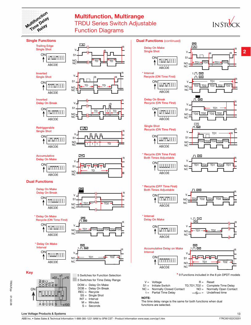
ON
A B C D E
Trailing Edge
Single Shot
ON
A B C D E
Inverted
Single Shot
ON
A B C D E
Inverted
Delay On Break
A B C D E
ON
Retriggerable
Single Shot
Key5 Switches for Function Selection
3 Switches for Time Delay Range
DOM = Delay On Make DOB = Delay On Break REC = Recycle SS = Single Shot INT = Interval M = Minutes S = Seconds
NOTE: The time delay range is the same for both functions when dual functions are selected.
Dual Functions
Single Functions
Multifunction, Multirange
TRDU Series Switch AdjustableFunction Diagrams
Multi
functio
n
Time D
elay
Relay
ON
A B C D E
Delay On Make
Delay On Break
ON
A B C D E
* Delay On Make
Recycle (ON Time First)
ON
A B C D E
Accumulative
Delay On Make
ON
A B C D E
* Recycle (ON Time First)
Both Times Adjustable
ON
A B C D E
* Recycle (OFF Time First)
Both Times Adjustable
ON
A B C D E
* Delay On Make
Interval
ON
A B C D E
Delay On Break
Recycle (ON Time First)
A B C D E
ON
Delay On Make
Single Shot
ON
A B C D E
* Interval
Recycle (ON Time First)
ON
A B C D E
Single Shot
Recycle (ON Time First)
ON
A B C D E
* Interval
Delay On Make
ON
A B C D E
Accumulative Delay on Make
Interval
* 9 Functions included in the 8 pin DPDT models
Dual Functions (continued)
V = Voltage R = Reset S1 = Initiate Switch TD,TD1,TD2 = Complete Time Delay NC = Normally Closed Contact NO = Normally Open Contact t = Partial Time Delay = Undefined time
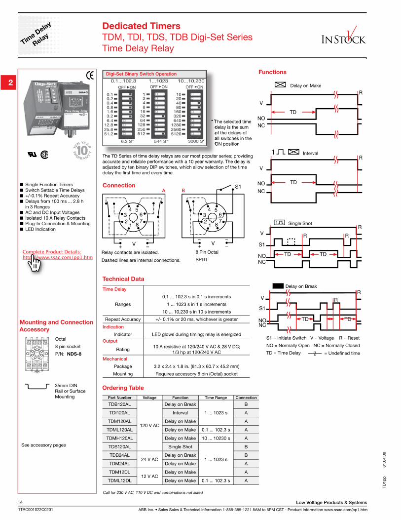
ABB Inc. • Sales Sales & Technical Information 1-888-385-1221 8AM to 5PM CST - Product Information www.ssac.com/pp1.htm
Low Voltage Products & Systems14
1TRC001022C0201
Dedicated Timers
TDM, TDI, TDS, TDB Digi-Set SeriesTime Delay Relay
Functions
Octal
8 pin socket
P/N: NDS-8
Single Function Timers Switch Settable Time Delays +/-0.1% Repeat Accuracy Delays from 100 ms ... 2.8 h
in 3 Ranges AC and DC Input Voltages Isolated 10 A Relay Contacts Plug-In Connection & Mounting LED Indication
The TD Series of time delay relays are our most popular series; providing accurate and reliable performance with a 10 year warranty. The delay is adjusted by ten binary DIP switches, which allow selection of the time delay the first time and every time.
Delay on Make
S1 = Initiate Switch V = Voltage R = Reset
NO = Normally Open NC = Normally Closed
TD = Time Delay
Delay on Break
Interval
Single Shot
Part Number Voltage Function Time Range Connection
TDB120AL
120 V AC
Delay on Break
1 ... 1023 s
B
TDI120AL Interval A
TDM120AL Delay on Make A
TDML120AL Delay on Make 0.1 ... 102.3 s A
TDMH120AL Delay on Make 10 ... 10230 s A
TDS120AL Single Shot
1 ... 1023 s
B
TDB24AL24 V AC
Delay on Break B
TDM24AL Delay on Make A
TDM12DL12 V AC
Delay on Make A
TDML12DL Delay on Make 0.1 ... 102.3 s A
Ordering Table
Time Delay
Ranges
0.1 ... 102.3 s in 0.1 s increments
1 ... 1023 s in 1 s increments
10 ... 10,230 s in 10 s increments
Repeat Accuracy +/- 0.1% or 20 ms, whichever is greater
Indication
Indicator LED glows during timing; relay is energizedOutput
Rating10 A resistive at 120/240 V AC & 28 V DC;
1/3 hp at 120/240 V ACMechanical
Package 3.2 x 2.4 x 1.8 in. (81.3 x 60.7 x 45.2 mm)
Mounting Requires accessory 8 pin (Octal) socket
Technical Data
Connection
Relay contacts are isolated.
Dashed lines are internal connections.
8 Pin Octal
SPDT
A B
Mounting and Connection
Accessory
* The selected time delay is the sum of the delays of all switches in the ON position
Call for 230 V AC, 110 V DC and combinations not listed
Digi-Set Binary Switch Operation
***
See accessory pages
TD1p
p
0
1.04
.08
Time D
elay
Relay
35mm DIN Rail or Surface Mounting
Low Voltage Products & Systems
ABB Inc. • Sales Sales & Technical Information 1-888-385-1221 8AM to 5PM CST - Product Information www.ssac.com/pp1.htm
15
1TRC001022C0201
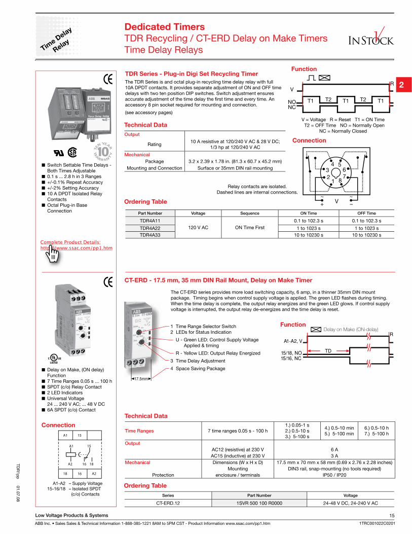
Switch Settable Time Delays - Both Times Adjustable
0.1 s ... 2.8 h in 3 Ranges +/-0.1% Repeat Accuracy +/-2% Setting Accuracy 10 A DPDT Isolated Relay
Contacts Octal Plug-in Base
Connection
Time D
elay
Relay
TDR Series - Plug-in Digi Set Recycling Timer
The TDR Series is and octal plug-in recycling time delay relay with full 10A DPDT contacts. It provides separate adjustment of ON and OFF time delays with two ten position DIP switches. Switch adjustment ensures accurate adjustment of the time delay the first time and every time. An accessory 8 pin socket required for mounting and connection.
(see accessory pages)
Function
V = Voltage R = Reset T1 = ON Time T2 = OFF Time NO = Normally Open
NC = Normally Closed
Connection
Relay contacts are isolated. Dashed lines are internal connections.
Dedicated Timers
TDR Recycling / CT-ERD Delay on Make Timers Time Delay Relays
Output
Rating10 A resistive at 120/240 V AC & 28 V DC;
1/3 hp at 120/240 V AC
Mechanical
Package 3.2 x 2.39 x 1.78 in. (81.3 x 60.7 x 45.2 mm)Mounting and Connection Surface or 35mm DIN rail mounting
Technical Data
1 Time Range Selector Switch2 LEDs for Status Indication
U - Green LED: Control Supply Voltage Applied & timing
R - Yellow LED: Output Relay Energized
3 Time Delay Adjustment
4 Space Saving Package
CT-ERD - 17.5 mm, 35 mm DIN Rail Mount, Delay on Make Timer
Delay on Make, (ON delay) Function
7 Time Ranges 0.05 s ... 100 h SPDT (c/o) Relay Contact 2 LED Indicators Universal Voltage
24 ... 240 V AC; ... 48 V DC 6A SPDT (c/o) Contact
The CT-ERD series provides more load switching capacity, 6 amp, in a thinner 35mm DIN mount package. Timing begins when control supply voltage is applied. The green LED flashes during timing. When the time delay is complete, the output relay energizes and the green LED glows. If control supply voltage is interrupted, the output relay de-energizes and the time delay is reset.
A1
A1
18
18
16
16
A2
A2
15
15
A1-A2 – Supply Voltage 15-16/18 – Isolated SPDT (c/o) Contacts
Time Ranges 7 time ranges 0.05 s - 100 h1.) 0.05-1 s 2.) 0.5-10 s3.) 5-100 s
4.) 0.5-10 min5.) 5-100 min
6.) 0.5-10 h7.) 5-100 h
Output
AC12 (resistive) at 230 V 6 AAC15 (inductive) at 230 V 3 A
Mechanical Dimensions (W x H x D) 17.5 mm x 70 mm x 58 mm (0.69 x 2.76 x 2.28 inches)Mounting DIN3 rail, snap-mounting (no tools required)
Protection enclosure / terminals IP50 / IP20
Series Part Number Voltage
CT-ERD.12 1SVR 500 100 R0000 24-48 V DC, 24-240 V AC
Ordering Table
TDR
1pp
01.07.08
Connection
Technical Data
Function
Part Number Voltage Sequence ON Time OFF Time
TDR4A11120 V AC ON Time First
0.1 to 102.3 s 0.1 to 102.3 s
TDR4A22 1 to 1023 s 1 to 1023 sTDR4A33 10 to 10230 s 10 to 10230 s
Ordering Table
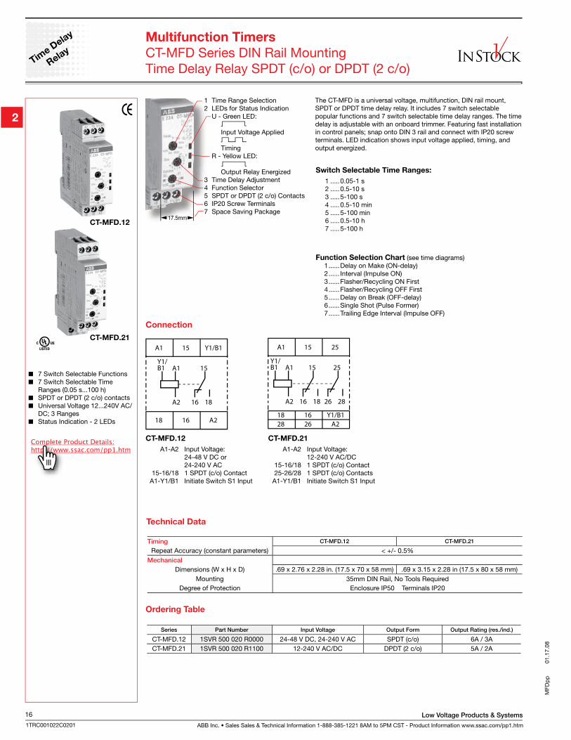
ABB Inc. • Sales Sales & Technical Information 1-888-385-1221 8AM to 5PM CST - Product Information www.ssac.com/pp1.htm
Low Voltage Products & Systems16
1TRC001022C0201
MFD
pp
01.
17.0
8
Time D
elay
Relay
A1
A1
28
28
26
26
A218 16 Y1/B1
A2
15
25
1816
15
25
Y1/B1
A1
A1
18
18
16
16
A2
A2
15
15
Y1/B1
Y1/B1
Multifunction Timers
CT-MFD Series DIN Rail MountingTime Delay Relay SPDT (c/o) or DPDT (2 c/o)
1 Time Range Selection2 LEDs for Status Indication U - Green LED:
Input Voltage Applied
Timing R - Yellow LED: Output Relay Energized3 Time Delay Adjustment4 Function Selector5 SPDT or DPDT (2 c/o) Contacts6 IP20 Screw Terminals7 Space Saving Package
The CT-MFD is a universal voltage, multifunction, DIN rail mount, SPDT or DPDT time delay relay. It includes 7 switch selectable popular functions and 7 switch selectable time delay ranges. The time delay is adjustable with an onboard trimmer. Featuring fast installation in control panels; snap onto DIN 3 rail and connect with IP20 screw terminals. LED indication shows input voltage applied, timing, and output energized.
Series Part Number Input Voltage Output Form Output Rating (res./ind.)
CT-MFD.12 1SVR 500 020 R0000 24-48 V DC, 24-240 V AC SPDT (c/o) 6A / 3ACT-MFD.21 1SVR 500 020 R1100 12-240 V AC/DC DPDT (2 c/o) 5A / 2A
7 Switch Selectable Functions 7 Switch Selectable Time
Ranges (0.05 s...100 h) SPDT or DPDT (2 c/o) contacts Universal Voltage 12...240V AC/
DC; 3 Ranges Status Indication - 2 LEDs
Switch Selectable Time Ranges:
1 .....0.05-1 s 2 .....0.5-10 s 3 .....5-100 s4 .....0.5-10 min 5 .....5-100 min 6 .....0.5-10 h7 .....5-100 h
CT-MFD.12
A1-A2 Input Voltage: 24-48 V DC or 24-240 V AC 15-16/18 1 SPDT (c/o) Contact A1-Y1/B1 Initiate Switch S1 Input
CT-MFD.21
A1-A2 Input Voltage: 12-240 V AC/DC 15-16/18 1 SPDT (c/o) Contact 25-26/28 1 SPDT (c/o) Contacts A1-Y1/B1 Initiate Switch S1 Input
Ordering Table
Connection
Timing CT-MFD.12 CT-MFD.21
Repeat Accuracy (constant parameters) < +/- 0.5%Mechanical
Dimensions (W x H x D) .69 x 2.76 x 2.28 in. (17.5 x 70 x 58 mm) .69 x 3.15 x 2.28 in (17.5 x 80 x 58 mm)Mounting 35mm DIN Rail, No Tools Required
Degree of Protection Enclosure IP50 Terminals IP20
Technical Data
CT-MFD.21
CT-MFD.12
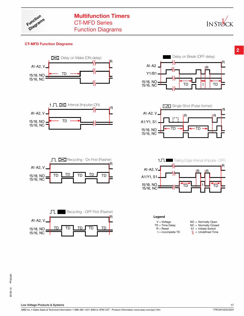
Function Selection Chart (see time diagrams) 1 ......Delay on Make (ON-delay) 2 ...... Interval (Impulse ON) 3 ......Flasher/Recycling ON First 4 ......Flasher/Recycling OFF First 5 ......Delay on Break (OFF-delay) 6 ......Single Shot (Pulse Former) 7 ......Trailing Edge Interval (Impulse OFF)
Low Voltage Products & Systems
ABB Inc. • Sales Sales & Technical Information 1-888-385-1221 8AM to 5PM CST - Product Information www.ssac.com/pp1.htm
17
1TRC001022C0201
MFD
Fpp
01.08.08
Multifunction Timers
CT-MFD SeriesFunction Diagrams
Function
Diagra
ms
CT-MFD Function Diagrams
V = Voltage NO = Normally Open TD = Time Delay NC = Normally Closed R = Reset S1 = Initiate Switch t = incomplete TD = Undefined Time
Legend
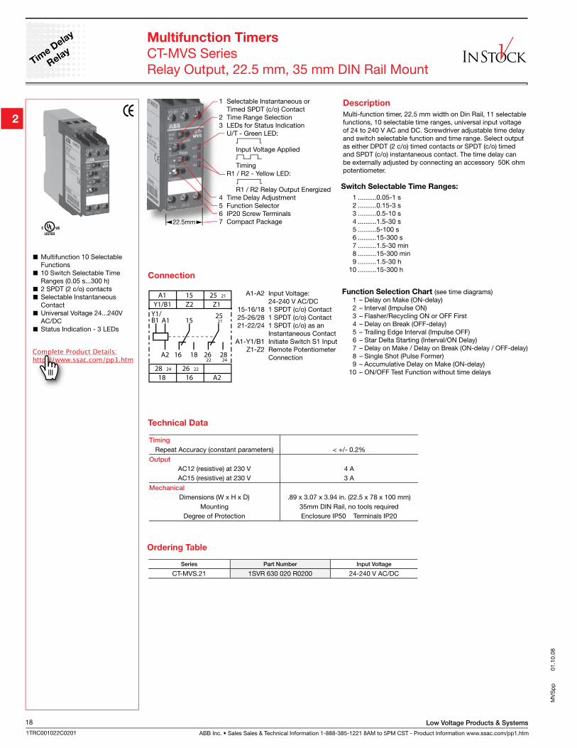
ABB Inc. • Sales Sales & Technical Information 1-888-385-1221 8AM to 5PM CST - Product Information www.ssac.com/pp1.htm
Low Voltage Products & Systems18
1TRC001022C0201
1 Selectable Instantaneous or Timed SPDT (c/o) Contact2 Time Range Selection3 LEDs for Status Indication U/T - Green LED:
Input Voltage Applied
Timing R1 / R2 - Yellow LED: R1 / R2 Relay Output Energized4 Time Delay Adjustment5 Function Selector6 IP20 Screw Terminals7 Compact Package
MV
Sp
p
0
1.10
.08
Time D
elay
Relay
Multifunction Timers
CT-MVS SeriesRelay Output, 22.5 mm, 35 mm DIN Rail Mount
Series Part Number Input Voltage
CT-MVS.21 1SVR 630 020 R0200 24-240 V AC/DC
Ordering Table
Multifunction 10 Selectable Functions
10 Switch Selectable Time Ranges (0.05 s...300 h)
2 SPDT (2 c/o) contacts Selectable Instantaneous Contact
Universal Voltage 24...240V AC/DC
Status Indication - 3 LEDs
Switch Selectable Time Ranges:
1 ..........0.05-1 s 2 ..........0.15-3 s 3 ..........0.5-10 s 4 ..........1.5-30 s 5 ..........5-100 s 6 ..........15-300 s 7 ..........1.5-30 min 8 ..........15-300 min 9 ..........1.5-30 h 10 ..........15-300 h
22.5mm
A1
A1Y1/B1 15
A2 16 18
15Z2
18 16 A2
Y1/B1 Z125 21
28 24 26 22
2125
26 2822 24
A1-A2 Input Voltage: 24-240 V AC/DC 15-16/18 1 SPDT (c/o) Contact 25-26/28 1 SPDT (c/o) Contact 21-22/24 1 SPDT (c/o) as an Instantaneous Contact A1-Y1/B1 Initiate Switch S1 Input Z1-Z2 Remote Potentiometer Connection
Timing
Repeat Accuracy (constant parameters) < +/- 0.2%Output
AC12 (resistive) at 230 V 4 AAC15 (resistive) at 230 V 3 A
Mechanical
Dimensions (W x H x D) .89 x 3.07 x 3.94 in. (22.5 x 78 x 100 mm)Mounting 35mm DIN Rail, no tools required
Degree of Protection Enclosure IP50 Terminals IP20
Technical Data
Connection
Description
Multi-function timer, 22.5 mm width on Din Rail, 11 selectable functions, 10 selectable time ranges, universal input voltage of 24 to 240 V AC and DC. Screwdriver adjustable time delay and switch selectable function and time range. Select output as either DPDT (2 c/o) timed contacts or SPDT (c/o) timed and SPDT (c/o) instantaneous contact. The time delay can be externally adjusted by connecting an accessory 50K ohm potentiometer.
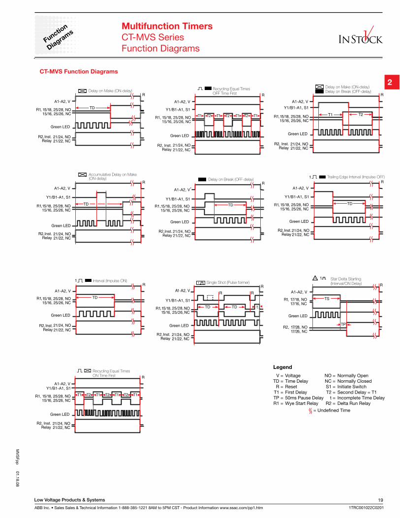
Function Selection Chart (see time diagrams) 1 – Delay on Make (ON-delay) 2 – Interval (Impulse ON) 3 – Flasher/Recycling ON or OFF First 4 – Delay on Break (OFF-delay) 5 – Trailing Edge Interval (Impulse OFF) 6 – Star Delta Starting (Interval/ON Delay) 7 – Delay on Make / Delay on Break (ON-delay / OFF-delay) 8 – Single Shot (Pulse Former) 9 – Accumulative Delay on Make (ON-delay) 10 – ON/OFF Test Function without time delays
Low Voltage Products & Systems
ABB Inc. • Sales Sales & Technical Information 1-888-385-1221 8AM to 5PM CST - Product Information www.ssac.com/pp1.htm
19
1TRC001022C0201
MV
SFp
p 01.18.08
CT-MVS Function Diagrams
V = Voltage NO = Normally Open TD = Time Delay NC = Normally Closed R = Reset S1 = Initiate Switch T1 = First Delay T2 = Second Delay = T1 TP = 50ms Pause Delay t = Incomplete Time Delay R1 = Wye Start Relay R2 = Delta Run Relay
= Undefined Time
Legend
Multifunction Timers
CT-MVS SeriesFunction Diagrams
Function
Diagra
ms
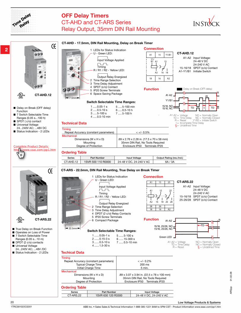
ABB Inc. • Sales Sales & Technical Information 1-888-385-1221 8AM to 5PM CST - Product Information www.ssac.com/pp1.htm
Low Voltage Products & Systems20
1TRC001022C0201
AR
Sp
p
0
1.02
.08
Time D
elay
Relay
Time D
elay
Relay
OFF Delay Timers
CT-AHD and CT-ARS SeriesRelay Output, 35mm DIN Rail Mounting
Delay on Break (OFF delay) Function
7 Switch Selectable Time Ranges (0.05 s...100 h)
SPDT ( c/o) contact Universal Voltage
24...240V AC; ...48V DC Status Indication - 2 LEDs
Series Part Number Input Voltage Output Rating (res./ind.)
CT-AHD.12 1SVR 500 110 R0000 24-48 V DC, 24-240 V AC 6A / 3A
Ordering Table
1 LEDs for Status Indication U - Green LED:
Input Voltage Applied
Timing R / R1 / R2 - Yellow LED: Output Relay Energized2 Time Range Selection3 Time Delay Adjustment4 SPDT (c/o) Contact5 IP20 Screw Terminals6 Space Saving Package
Function
Technical Data
1 LEDs for Status Indication U - Green LED:
Input Voltage Applied
Timing R / R1 / R2 - Yellow LED: Output Relay Energized2 Time Range Selection3 Time Delay Adjustment4 DPDT (2 c/o) Relay Contacts5 IP20 Screw Terminals6 Compact Package
A1
A1 15 25
A2 16 18 26 28
15
2628
25
18 16 A2
CT-ARS.22
A1-A2 Input Voltage: 24-48 V DC 24-240 V AC 15-16/18 SPDT (c/o) Contact 25-26/28 SPDT (c/o) Contact
True Delay on Break Function Operates on Loss of Power 7 Switch Selectable Time
Ranges (0.05 s...10 m) DPDT (2 c/o) contacts Universal Voltage
24...240V AC; ...48V /DC Status Indication - 2 LEDs
Series Part Number Input Voltage
CT-ARS.22 1SVR 630 120 R3300 24-48 V DC, 24-240 V AC
Connection
Function
Ordering Table
Timing
Repeat Accuracy (constant parameters) < +/- 0.2%Typical Charge Time 200 msInitial Charge Time 5 min.
Mechanical
Dimensions (W x H x D) .89 x 3.07 x 3.94 in. (22.5 x 78 x 100 mm)Mounting 35mm DIN Rail, No Tools Required
Degree of Protection Enclosure IP50 Terminals IP20
Techical Data
CT-ARS.22
CT-AHD.12
TimingRepeat Accuracy (constant parameters) < +/- 0.5%
Mechanical
Dimensions (W x H x D) .69 x 2.76 x 2.28 in. (17.5 x 70 x 58 mm)Mounting 35mm DIN Rail, No Tools Required
Degree of Protection Enclosure IP50 Terminals IP20
A1
A1
18
18
16
16
A2
A2
15
15
Y1/B1
Y1/B1
Connection
CT-AHD.12
A1-A2 Input Voltage: 24-48 V DC 24-240 V AC 15-16/18 SPDT (c/o) Contact A1-Y1/B1 Initiate Switch
CT-AHD - 17.5mm, DIN Rail Mounting, Delay on Break Timer
Switch Selectable Time Ranges:
1 .....0.05-1 s 2 .....0.5-10 s 3 .....5-100 s4 .....0.5-10 min
5 .....5-100 min 6 .....0.5-10 h7 .....5-100 h
CT-ARS - 22.5mm, DIN Rail Mounting, True Delay on Break Timer
Switch Selectable Time Ranges:
1 ......0.05-1 s 2 ......0.15-3 s 3 ......0.5-10 s 4 ......1.5-30 s
5 ......5-100 s 6 ......15-300 s 7 ......0.5-10 min
Low Voltage Products & Systems
ABB Inc. • Sales Sales & Technical Information 1-888-385-1221 8AM to 5PM CST - Product Information www.ssac.com/pp1.htm
21
1TRC001022C0201
KS
D1p
p 12.28.07
Accurate General Purpose Timers
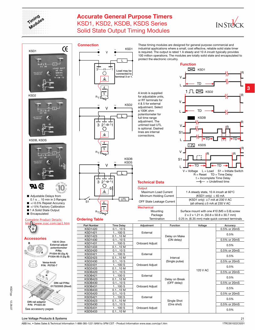
KSD1, KSD2, KSDB, KSDS SeriesSolid State Output Timing Modules
Adjustable Delays from 0.1 s ... 10 min in 3 Ranges
+/-0.5% Repeat Accuracy +/-5% Factory Calibration 1 A Solid State Output Encapsulated
These timing modules are designed for general purpose commercial and industrial applications where a small, cost effective, reliable solid state timer is required. The output is rated 1 A steady and 10 A inrush typically provides 100 million operations. The modules are totally solid state and encapsulated to protect the electronic circuitry.
Function
100 K OhmExternal adjustpotentiometer
P/Ns: P1004-95 (�g A)
P1004-95-X (�g B)
Accessories
Connection
Versa-knobP/N: P0700-7
DIN rail adaptorP/N: P1023-20
DIN rail P/Ns:
017322005 (Steel)
Output
Maximum Load Current 1 A steady state, 10 A inrush at 60°CMinimum Holding Current (KSD1 only) ≤ 40 mA
OFF State Leakage Current(KSD1 only) 7 mA at 230 V AC(all others) 5 mA at 230 V AC
Mechanical
Mounting Surface mount with one #10 (M5 x 0.8) screwPackage 2 x 2 x 1.21 in. (50.8 x 50.8 x 30.7 mm)
Termination 0.25 in. (6.35 mm) male quick connect terminals
See accessory pages
KSD1
KSD2
KSD2
A knob is supplied for adjustable units, or RT terminals for 4 & 5 for external adjustment. Select a 100K ohm potentiometer for full time range adjustment. The untimed load UTL is optional. Dashed lines are internal connections.
KSD1
KSDBKSDS
Load may be connected to
terminal 3 or 1.
V = Voltage L = Load S1 = Initiate SwitchR = Reset TD = Time Delay
t = Incomplete Time Delay
KSDB
KSDS
Part Number Time Delay Adjustment Function Voltage Accuracy
KSD1420 0.1...10 SExternal
Delay on Make(ON delay)
120 V AC
0.5% or 20mSKSD1421 1…100 S
0.5%KSD1423 0.1...10 MKSD1430 0.1...10 S
Onboard Adjust0.5% or 20mS
KSD1431 1…100 S0.5%
KSD1433 0.1...10 MKSD2420 0.1...10 S
ExternalInterval
(Single pulse)
0.5% or 20mSKSD2421 1…100 S
0.5%KSD2423 0.1...10 MKSD2430 0.1...10 S
Onboard Adjust0.5% or 20mS
KSD2431 1…100 S0.5%
KSD2433 0.1...10 MKSDB420 0.1...10 S
ExternalDelay on Break
(OFF delay)
0.5% or 20mSKSDB421 1…100 S
0.5%KSDB423 0.1...10 MKSDB430 0.1...10 S
Onboard Adjust0.5% or 20mS
KSDB431 1…100 S0.5%
KSDB433 0.1...10 MKSDS420 0.1...10 S
ExternalSingle Shot(One shot)
0.5% or 20mSKSDS421 1…100 S
0.5%KSDS423 0.1...10 MKSDS430 0.1...10 S
Onboard Adjust0.5% or 20mS
KSDS431 1…100 S0.5%
KSDS433 0.1...10 M
Ordering Table
Technical Data
KSD1
KSD2
KSDB, KSDS
Timin
g
Module
s
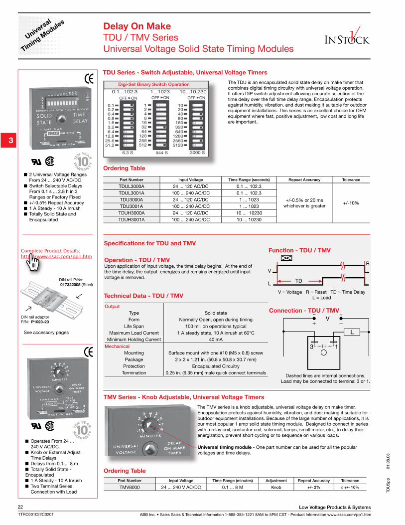
ABB Inc. • Sales Sales & Technical Information 1-888-385-1221 8AM to 5PM CST - Product Information www.ssac.com/pp1.htm
Low Voltage Products & Systems22
1TRC001022C0201
TDU
5pp
01.
08.0
8
2 Universal Voltage Ranges From 24 ... 240 V AC/DC
Switch Selectable Delays From 0.1 s ... 2.8 h in 3 Ranges or Factory Fixed
+/-0.5% Repeat Accuracy 1 A Steady - 10 A Inrush Totally Solid State and
Encapsulated
TDU Series - Switch Adjustable, Universal Voltage Timers
Operation - TDU / TMVUpon application of input voltage, the time delay begins. At the end of the time delay, the output energizes and remains energized until input voltage is removed.
Function - TDU / TMV
V = Voltage R = Reset TD = Time DelayL = Load
Connection - TDU / TMV
Dashed lines are internal connections.Load may be connected to terminal 3 or 1.
Digi-Set Binary Switch Operation
Output
Type Solid stateForm Normally Open, open during timing
Life Span 100 million operations typicalMaximum Load Current 1 A steady state, 10 A inrush at 60°C
Minimum Holding Current 40 mAMechanical
Mounting Surface mount with one #10 (M5 x 0.8) screwPackage 2 x 2 x 1.21 in. (50.8 x 50.8 x 30.7 mm)
Protection Encapsulated CircuitryTermination 0.25 in. (6.35 mm) male quick connect terminals
Part Number Input Voltage Time Range (seconds) Repeat Accuracy Tolerance
TDUL3000A 24 ... 120 AC/DC 0.1 ... 102.3
+/-0.5% or 20 mswhichever is greater
+/-10%
TDUL3001A 100 ... 240 AC/DC 0.1 ... 102.3TDU3000A 24 ... 120 AC/DC 1 ... 1023TDU3001A 100 ... 240 AC/DC 1 ... 1023
TDUH3000A 24 ... 120 AC/DC 10 ... 10230TDUH3001A 100 ... 240 AC/DC 10 ... 10230
Delay On Make
TDU / TMV SeriesUniversal Voltage Solid State Timing Modules
Operates From 24 ... 240 V AC/DC
Knob or External Adjust Time Delays
Delays from 0.1 ... 8 m Totally Solid State -
Encapsulated 1 A Steady - 10 A Inrush Two Terminal Series
Connection with Load
TMV Series - Knob Adjustable, Universal Voltage Timers
Part Number Input Voltage Time Range (minutes) Adjustment Repeat Accuracy Tolerance
TMV8000 24 ... 240 V AC/DC 0.1 ... 8 M Knob +/- 2% ≤ +/- 10%
Ordering Table
Ordering Table
Technical Data - TDU / TMV
Specifications for TDU and TMV
Universal
Timin
g Module
s
DIN rail P/Ns: 017322005 (Steel)
DIN rail adaptorP/N: P1023-20
See accessory pages
The TDU is an encapsulated solid state delay on make timer that combines digital timing circuitry with universal voltage operation. It offers DIP switch adjustment allowing accurate selection of the time delay over the full time delay range. Encapsulation protects against humidity, vibration, and dust making it suitable for outdoor equipment installations. This series is an excellent choice for OEM equipment where fast, positive adjustment, low cost and long life are important..
The TMV series is a knob adjustable, universal voltage delay on make timer. Encapsulation protects against humidity, vibration, and dust making it suitable for outdoor equipment installations. Because of the large number of applications, it is our most popular 1 amp solid state timing module. Designed to connect in series with a relay coil, contactor coil, solenoid, lamps, small motor, etc., to delay their energization, prevent short cycling or to sequence on various loads.
Universal timing module - One part number can be used for all the popular voltages and time delays.
Low Voltage Products & Systems
ABB Inc. • Sales Sales & Technical Information 1-888-385-1221 8AM to 5PM CST - Product Information www.ssac.com/pp1.htm
23
1TRC001022C0201
FS-R
Sp
p 01.07.08
Flasher a
nd
Recycling T
imer
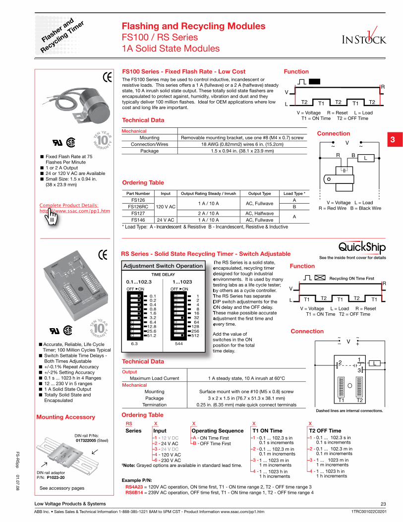
Fixed Flash Rate at 75 Flashes Per Minute
1 or 2 A Output 24 or 120 V AC are Available Small Size: 1.5 x 0.94 in.
(38 x 23.9 mm)
Flashing and Recycling Modules
FS100 / RS Series1A Solid State Modules
Connection
V = Voltage L = LoadR = Red Wire B = Black Wire
Function
V = Voltage R = Reset L = LoadT1 = ON Time T2 = OFF Time
Ordering Table
FS100 Series - Fixed Flash Rate - Low Cost
The FS100 Series may be used to control inductive, incandescent or resistive loads. This series offers a 1 A (fullwave) or a 2 A (halfwave) steady state, 10 A inrush solid state output. These totally solid state flashers are encapsulated to protect against, humidity, vibration and dust and they typically deliver 100 million flashes. Ideal for OEM applications where low cost and long life are important.
Part Number Input Output Rating Steady / Inrush Output Type Load Type *
FS126120 V AC
1 A / 10 A AC, FullwaveA
FS126RC BFS127 2 A / 10 A AC, Halfwave
AFS146 24 V AC 1 A / 10 A AC, Fullwave
* Load Type: A - Incandescent & Resistive B - Incandescent, Resistive & Inductive
Technical Data
Mechanical
Mounting Removable mounting bracket, use one #8 (M4 x 0.7) screwConnection/Wires 18 AWG (0.82mm2) wires 6 in. (15.2cm)
Package 1.5 x 0.94 in. (38.1 x 23.9 mm)
Accurate, Reliable, Life Cycle Timer; 100 Million Cycles Typical
Switch Settable Time Delays - Both Times Adjustable
+/-0.1% Repeat Accuracy +/-2% Setting Accuracy 0.1 s ... 1023 h in 4 Ranges 12 ... 230 V in 5 ranges 1 A Solid State Output Totally Solid State and
Encapsulated
The RS Series is a solid state, encapsulated, recycling timer designed for tough industrial environments. It is used by many testing labs as a life cycle tester; by others as a cycle controller. The RS Series has separate DIP switch adjustments for the ON delay and the OFF delay. These make possible accurate adjustment the first time and every time.
Function
V = Voltage L = Load R = ResetT1 = ON Time T2 = OFF Time
Add the value of switches in the ON position for the total time delay.
Dashed lines are internal connections.
Connection
RS Series - Solid State Recycling Timer - Switch Adjustable
RS X X X X
–1 -
–2 -
–3 -
–4 -
Series Input Operating Sequence T1 ON Time T2 OFF Time
Example P/N:
0.1 ... 102.3 s in0.1 s increments0.1 ... 102.3 m in0.1 m increments1 ... 1023 m in 1 m increments1 ... 1023 h in 1 h increments
Ordering Table
–1 -
–2 -
–3 -
–4 -
–6 -
12 V DC24 V AC24 V DC120 V AC230 V AC
–A -
–B -ON Time FirstOFF Time First
–1 -
–2 -
–3 -
–4 -
0.1 ... 102.3 s in0.1 s increments0.1 ... 102.3 m in0.1 m increments1 ... 1023 m in1 m increments1 ... 1023 h in 1 h increments
Output
Maximum Load Current 1 A steady state, 10 A inrush at 60°CMechanical
Mounting Surface mount with one #10 (M5 x 0.8) screwPackage 3 x 2 x 1.5 in (76.7 x 51.3 x 38.1 mm)
Termination 0.25 in. (6.35 mm) male quick connect terminals
Technical Data
†Note: Grayed options are available in standard lead time.
DIN rail P/Ns: 017322005 (Steel)
DIN rail adaptorP/N: P1023-20
See accessory pages
Mounting Accessory
See the inside front cover for details
Recycling ON Time First
RS4A23 = 120V AC operation, ON time first, T1 - ON time range 2, T2 - OFF time range 3 RS6B14 = 239V AC operation, OFF time first, T1 - ON time range 1, T2 - OFF time range 4
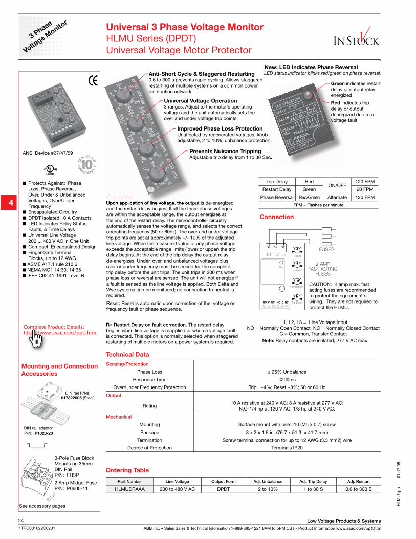
ABB Inc. • Sales Sales & Technical Information 1-888-385-1221 8AM to 5PM CST - Product Information www.ssac.com/pp1.htm
Low Voltage Products & Systems24
1TRC001022C0201
ANSI Device #27/47/59
Protects Against: Phase Loss, Phase Reversal, Over, Under & Unbalanced Voltages, Over/Under Frequency
Encapsulated Circuitry DPDT Isolated 10 A Contacts LED Indicates Relay Status,
Faults, & Time Delays Universal Line Voltage
200 ... 480 V AC in One Unit Compact, Encapsulated Design Finger-Safe Terminal
Blocks, up to 12 AWG ASME A17.1 rule 210.6 NEMA MG1 14:30, 14:35 IEEE C62.41-1991 Level B
See accessory pages
DIN rail P/Ns:017322005 (Steel)
DIN rail adaptorP/N: P1023-20
Universal 3 Phase Voltage Monitor
HLMU Series (DPDT)Universal Voltage Motor Protector
OperationUpon application of line voltage, the output is de-energized and the restart delay begins. If all the three phase voltages are within the acceptable range, the output energizes at the end of the restart delay. The microcontroller circuitry automatically senses the voltage range, and selects the correct operating frequency (50 or 60hz). The over and under voltage trip points are set at approximately +/- 10% of the adjusted line voltage. When the measured value of any phase voltage exceeds the acceptable range limits (lower or upper) the trip delay begins. At the end of the trip delay the output relay de-energizes. Under, over, and unbalanced voltages plus over or under frequency must be sensed for the complete trip delay before the unit trips. The unit trips in 200 ms when phase loss or reversal are sensed. The unit will not energize if a fault is sensed as the line voltage is applied. Both Delta and Wye systems can be monitored; no connection to neutral is required.
Reset: Reset is automatic upon correction of the voltage or frequency fault or phase sequence.
R= Restart Delay on fault correction. The restart delay begins when line voltage is reapplied or when a voltage fault is corrected. This option is normally selected when staggered restarting of multiple motors on a power system is required.
Connection
CAUTION: 2 amp max. fast acting fuses are recommended to protect the equipment‘s wiring. They are not required to protect the HLMU.
L1, L2, L3 = Line Voltage InputNO = Normally Open Contact NC = Normally Closed Contact
C = Common, Transfer ContactNote: Relay contacts are isolated, 277 V AC max.
Sensing/Protection
Phase Loss ≥ 25% Unbalance
Response Time ≤200ms
Over/Under Frequency Protection Trip ±4%; Reset ±3%; 50 or 60 Hz
Output
Rating10 A resistive at 240 V AC; 8 A resistive at 277 V AC;
N.O-1/4 hp at 120 V AC; 1/3 hp at 240 V AC;
Mechanical
Mounting Surface mount with one #10 (M5 x 0.7) screw
Package 3 x 2 x 1.5 in. (76.7 x 51.3 x 41.7 mm)
Termination Screw terminal connection for up to 12 AWG (3.3 mm2) wire
Degree of Protection Terminals IP20
Anti-Short Cycle & Staggered Restarting0.6 to 300 s prevents rapid cycling. Allows staggered restarting of multiple systems on a common power distribution network.
Universal Voltage Operation3 ranges. Adjust to the motor’s operating voltage and the unit automatically sets the over and under voltage trip points.
Improved Phase Loss ProtectionUnaffected by regenerated voltages, knob adjustable, 2 to 10%, unbalance protection.
Prevents Nuisance TrippingAdjustable trip delay from 1 to 30 Sec.
3 Phase
Voltage M
onitor
Trip Delay RedON/OFF
120 FPM
Restart Delay Green 60 FPM
Phase Reversal Red/Green Alternate 120 FPM
FPM = Flashes per minute
Ordering Table
Technical Data
Part Number Line Voltage Output Form Adj. Unbalance Adj. Trip Delay Adj. Restart
HLMUDRAAA 200 to 480 V AC DPDT 2 to 10% 1 to 30 S 0.6 to 300 S
Mounting and Connection
Accessories
HLM
U1p
p
0
1.17
.08
P/N: FH3P
2 Amp Midget FuseP/N: P0600-11
3-Pole Fuse BlockMounts on 35mm DIN Rail
New: LED Indicates Phase Reversal
Green indicates restart delay or output relay energized
Red indicates trip delay or output denergized due to a voltage fault
LED status indicator blinks red/green on phase reversal.
Low Voltage Products & Systems
ABB Inc. • Sales Sales & Technical Information 1-888-385-1221 8AM to 5PM CST - Product Information www.ssac.com/pp1.htm
25
1TRC001022C0201
DLM
Up
p 01.18.08
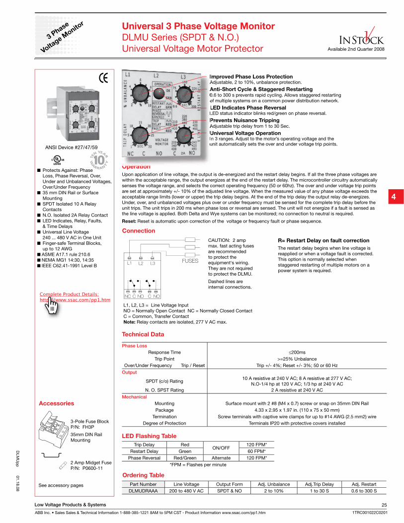
ANSI Device #27/47/59
Protects Against: Phase Loss, Phase Reversal, Over, Under and Unbalanced Voltages, Over/Under Frequency
35 mm DIN Rail or Surface Mounting
SPDT Isolated 10 A Relay Contacts
N.O. Isolated 2A Relay Contact LED Indicates, Relay, Faults,
& Time Delays Universal Line Voltage
240 ... 480 V AC in One Unit Finger-safe Terminal Blocks,
up to 12 AWG ASME A17.1 rule 210.6 NEMA MG1 14:30, 14:35 IEEE C62.41-1991 Level B
Universal 3 Phase Voltage Monitor
DLMU Series (SPDT & N.O.)Universal Voltage Motor Protector
Operation
Upon application of line voltage, the output is de-energized and the restart delay begins. If all the three phase voltages are within the acceptable range, the output energizes at the end of the restart delay. The microcontroller circuitry automatically senses the voltage range, and selects the correct operating frequency (50 or 60hz). The over and under voltage trip points are set at approximately +/- 10% of the adjusted line voltage. When the measured value of any phase voltage exceeds the acceptable range limits (lower or upper) the trip delay begins. At the end of the trip delay the output relay de-energizes. Under, over, and unbalanced voltages plus over or under frequency must be sensed for the complete trip delay before the unit trips. The unit trips in 200 ms when phase loss or reversal are sensed. The unit will not energize if a fault is sensed as the line voltage is applied. Both Delta and Wye systems can be monitored; no connection to neutral is required.
Reset: Reset is automatic upon correction of the voltage or frequency fault or phase sequence.
Accessories
Connection
L1, L2, L3 = Line Voltage Input NO = Normally Open Contact NC = Normally Closed ContactC = Common, Transfer ContactNote: Relay contacts are isolated, 277 V AC max.
CAUTION: 2 amp max. fast acting fuses are recommended to protect the equipment‘s wiring. They are not required to protect the DLMU.
Dashed lines are internal connections.
R= Restart Delay on fault correction
The restart delay begins when line voltage is reapplied or when a voltage fault is corrected. This option is normally selected when staggered restarting of multiple motors on a power system is required.
See accessory pages
Improved Phase Loss ProtectionAdjustable, 2 to 10%, unbalance protection.
Anti-Short Cycle & Staggered Restarting0.6 to 300 s prevents rapid cycling. Allows staggered restarting of multiple systems on a common power distribution network.
LED Indicates Phase Reversal LED status indicator blinks red/green on phase reversal.
Prevents Nuisance TrippingAdjustable trip delay from 1 to 30 Sec.
Universal Voltage OperationIn 3 ranges. Adjust to the motor’s operating voltage and the unit automatically sets the over and under voltage trip points.
LED Flashing Table
Trip Delay RedON/OFF
120 FPM*Restart Delay Green 60 FPM*
Phase Reversal Red/Green Alternate 120 FPM**FPM = Flashes per minute
Part Number Line Voltage Output Form Adj. Unbalance Adj.Trip Delay Adj. RestartDLMUDRAAA 200 to 480 V AC SPDT & NO 2 to 10% 1 to 30 S 0.6 to 300 S
Ordering Table
Phase Loss
Response Time ≤200msTrip Point >=25% Unbalance
Over/Under Frequency Trip / Reset Trip +/- 4%; Reset +/- 3%; 50 or 60 HzOutput
SPDT (c/o) Rating10 A resistive at 240 V AC; 8 A resistive at 277 V AC;
N.O-1/4 hp at 120 V AC; 1/3 hp at 240 V ACN. O. SPST Rating 2 A resistive at 240 V AC
Mechanical
Mounting Surface mount with 2 #8 (M4 x 0.7) screw or snap on 35mm DIN RailPackage 4.33 x 2.95 x 1.97 in. (110 x 75 x 50 mm)
Termination Screw terminals with captive wire clamps for up to #14 AWG (2.5 mm2) wireDegree of Protection Terminals IP20 with protective covers installed
Technical Data
Available 2nd Quarter 2008
3-Pole Fuse BlockP/N: FH3P
35mm DIN RailMounting
2 Amp Midget FuseP/N: P0600-11
3 Phase
Voltage M
onitor
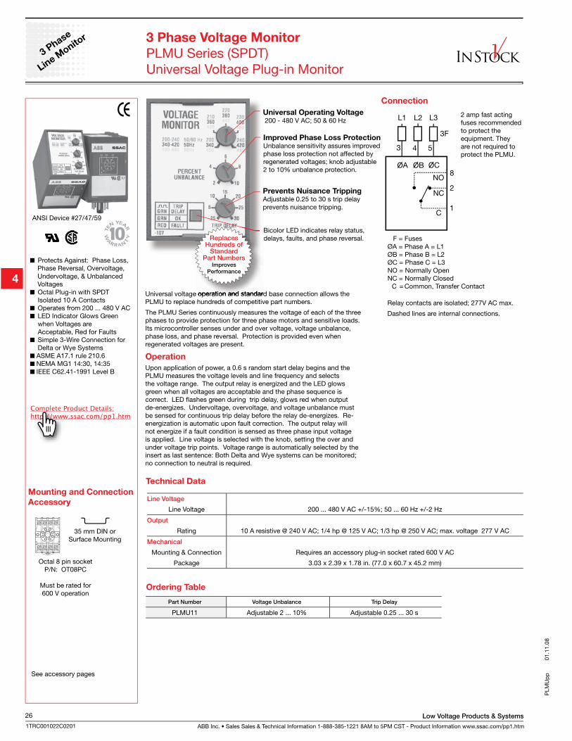
ABB Inc. • Sales Sales & Technical Information 1-888-385-1221 8AM to 5PM CST - Product Information www.ssac.com/pp1.htm
Low Voltage Products & Systems26
1TRC001022C0201
3 Phase
Line M
onitor
ANSI Device #27/47/59
Protects Against: Phase Loss, Phase Reversal, Overvoltage, Undervoltage, & Unbalanced Voltages
Octal Plug-in with SPDT Isolated 10 A Contacts
Operates from 200 ... 480 V AC LED Indicator Glows Green
when Voltages are Acceptable, Red for Faults
Simple 3-Wire Connection for Delta or Wye Systems
ASME A17.1 rule 210.6 NEMA MG1 14:30, 14:35 IEEE C62.41-1991 Level B
Connection
F = FusesØA = Phase A = L1ØB = Phase B = L2ØC = Phase C = L3NO = Normally Open NC = Normally Closed C = Common, Transfer Contact
Relay contacts are isolated; 277V AC max.
Dashed lines are internal connections.
2 amp fast acting fuses recommended to protect the equipment. They are not required to protect the PLMU.
3 Phase Voltage Monitor
PLMU Series (SPDT)Universal Voltage Plug-in Monitor
Universal voltage operation and standard base connection allows the PLMU to replace hundreds of competitive part numbers.
The PLMU Series continuously measures the voltage of each of the three phases to provide protection for three phase motors and sensitive loads. Its microcontroller senses under and over voltage, voltage unbalance, phase loss, and phase reversal. Protection is provided even when regenerated voltages are present.
Operation
Upon application of power, a 0.6 s random start delay begins and the PLMU measures the voltage levels and line frequency and selects the voltage range. The output relay is energized and the LED glows green when all voltages are acceptable and the phase sequence is correct. LED flashes green during trip delay, glows red when output de-energizes. Undervoltage, overvoltage, and voltage unbalance must be sensed for continuous trip delay before the relay de-energizes. Re-energization is automatic upon fault correction. The output relay will not energize if a fault condition is sensed as three phase input voltage is applied. Line voltage is selected with the knob, setting the over and under voltage trip points. Voltage range is automatically selected by the insert as last sentence: Both Delta and Wye systems can be monitored; no connection to neutral is required.
Line Voltage
Line Voltage 200 ... 480 V AC +/-15%; 50 ... 60 Hz +/-2 Hz
Output
Rating 10 A resistive @ 240 V AC; 1/4 hp @ 125 V AC; 1/3 hp @ 250 V AC; max. voltage 277 V AC
Mechanical
Mounting & Connection Requires an accessory plug-in socket rated 600 V AC
Package 3.03 x 2.39 x 1.78 in. (77.0 x 60.7 x 45.2 mm)
Part Number Voltage Unbalance Trip Delay
PLMU11 Adjustable 2 ... 10% Adjustable 0.25 ... 30 s
Ordering Table
Octal 8 pin socketP/N: OT08PC
Must be rated for 600 V operation
Mounting and Connection
Accessory
Universal Operating Voltage 200 - 480 V AC; 50 & 60 Hz
Improved Phase Loss ProtectionUnbalance sensitivity assures improved phase loss protection not affected by regenerated voltages; knob adjustable 2 to 10% unbalance protection.
Prevents Nuisance TrippingAdjustable 0.25 to 30 s trip delay prevents nuisance tripping.
Bicolor LED indicates relay status, delays, faults, and phase reversal.
Technical Data
PLM
Up
p
0
1.11
.08
ReplacesHundreds of
StandardPart Numbers
ImprovesPerformance
35 mm DIN or Surface Mounting
See accessory pages
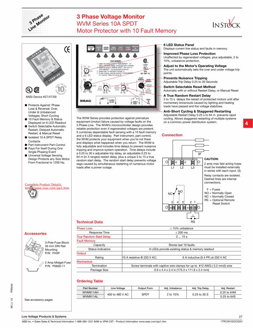
Low Voltage Products & Systems
ABB Inc. • Sales Sales & Technical Information 1-888-385-1221 8AM to 5PM CST - Product Information www.ssac.com/pp1.htm
27
1TRC001022C0201
WV
Mp
p 01.17.08
The WVM Series provides protection against premature equipment (motor) failure caused by voltage faults on the 3 Phase Line. The WVM’s microcontroller design provides reliable protection even if regenerated voltages are present. It combines dependable fault sensing with a 10 fault memory and a 6 LED status display. Part instrument, part control, the WVM protects your equipment when you’re not there and displays what happened when you return. The WVM is fully adjustable and includes time delays to prevent nuisance tripping and improve system operation. Time delays include a 0.25 to 30 s adjustable trip delay, an adjustable 0.25 to 64 m (in 3 ranges) restart delay, plus a unique 3 to 15 s true random start delay. The random start delay prevents voltage sags caused by simultaneous restarting of numerous motor loads after a power outage.
3 Phase Voltage Monitor
WVM Series 10A SPDTMotor Protector with 10 Fault Memory
Protects Against: Phase Loss & Reversal; Over, Under & Unbalanced Voltages; Short Cycling
10 Fault Memory & Status Displayed on 6 LED Readout
Switch Selectable Automatic Restart, Delayed Automatic Restart, & Manual Reset
Isolated 10 A SPDT Relay Contacts
Part Instrument Part Control Pays For Itself During One
Single Phasing Event Universal Voltage Sensing
Design Protects any Size Motor. From Fractional to 1200 Hp.
ANSI Device #27/47/59
Connection
F = Fuses NO = Normally Open NC = Normally ClosedRS = Optional Remote Reset Switch
CAUTION:
2 amp max fast acting fuses must be installed externally in series with each input. (3)
Relay contacts are isolated.Dashed lines are internal connections.
3 Phase
Line M
onitor
Phase Loss ≥ 15% unbalanceResponse Time ≤ 200 ms
True Random Start Delay 3 ... 15 sFault Memory
Capacity Stores last 10 faultsStatus Indicators 6 LEDs provide existing status & memory readout
Output
Rating 10 A resistive @ 250 V AC; 6 A inductive (0.4 PF) at 250 V ACMechanical
Termination Screw terminals with captive wire clamps for up to #12 AWG ( 3.2 mm2) wirePackage Size 6.9 x 4.4 x 2.4 in (175.3 x 111.8 x 2.4 mm)
Technical Data
Part Number Line Voltage Output Form Adj. Unbalance Adj. Trip Delay Adj. Restart
WVM911AH400 to 480 V AC SPDT 2 to 10% 0.25 to 30 S
0.25 to 64MWVM911AL 0.25 to 64S
Ordering Table
Accessories
See accessory pages
3-Pole Fuse Block35 mm DIN Rail MountingP/N: FH3P
2 Amp Midget FuseP/N: P0600-11
6 LED Status Panel Displays current line status and faults in memory.
Improved Phase Loss ProtectionUnaffected by regenerated voltages, plus adjustable, 2 to 10%, unbalance protection.
Adjust to the Motor’s Operating VoltageThe unit automatically sets the over and under voltage trip points.
Prevents Nuisance TrippingAdjustable Trip Delay 0.25 to 30 Seconds
Switch Selectable Reset MethodAutomatic with or without Restart Delay, or Manual Reset
A True Random Restart Delay3 to 15 s delays the restart of protected motors until after momentary brownouts caused by lighting and heating loads have passed and the voltage stabilizes.
Anti-Short Cycling & Staggered RestartingAdjustable Restart Delay 0.25 s to 64 m prevents rapid cycling. Allows staggered restarting of multiple systems on a common power distribution system.
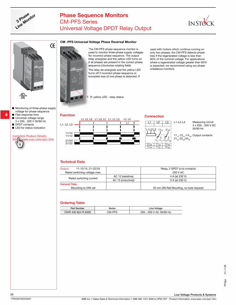
ABB Inc. • Sales Sales & Technical Information 1-888-385-1221 8AM to 5PM CST - Product Information www.ssac.com/pp1.htm
Low Voltage Products & Systems28
1TRC001022C0201
PFS
pp
01.
17.0
8
Monitoring of three-phase supply voltage for phase sequence
Fast response time Universal voltage range
3 x 200…500 V 50/60 Hz DPDT contacts LED for status indication
Phase Sequence Monitors
CM-PFS SeriesUniversal Voltage DPDT Relay Output
CM -PFS Universal Voltage Phase Reversal Monitor
Connection
3 Phase
Line M
onitor
Function
L1, L2, L3
21/2421/22
11/14 11/12
L1-L2-L3
1115-1216 /1418, Output contacts2125-2226/2428
Measuring circuit3 x 200…500 V AC 50/60 Hz
Ordering Table
Part Number Series Line Voltage
1SVR 430 824 R 9300 CM-PFS 200…500 V AC 50/60 Hz
Output 11-12/14, 21-22/24 Relay, 2 SPDT (c/o) contactsRated switching voltage max. 250 V AC
Rated switching currentAC 12 (resistive) 4 A (at 230 V)
AC 15 (inductive)) 3 A (at 230 V)General Data
Mounting to DIN rail 35 mm DIN Rail Mounting, no tools required
Technical Data
The CM-PFS phase sequence monitor is used to monitor three-phase supply voltages for incorrect phase sequence. The output relay energizes and the yellow LED turns on if all phases are present in the correct phase sequence (clockwise rotating field).
The relay de-energizes and the yellow LED turns off if incorrect phase sequence or complete loss of one phase is detected. If
1 R: yellow LED - relay status
used with motors which continue running on only two phases, the CM-PFS detects phase loss if the regenerated voltage is less than 60% of the nominal voltage. For applications where a regenerated voltage greater than 60% is expected, we recommend using our phase unbalance monitors.
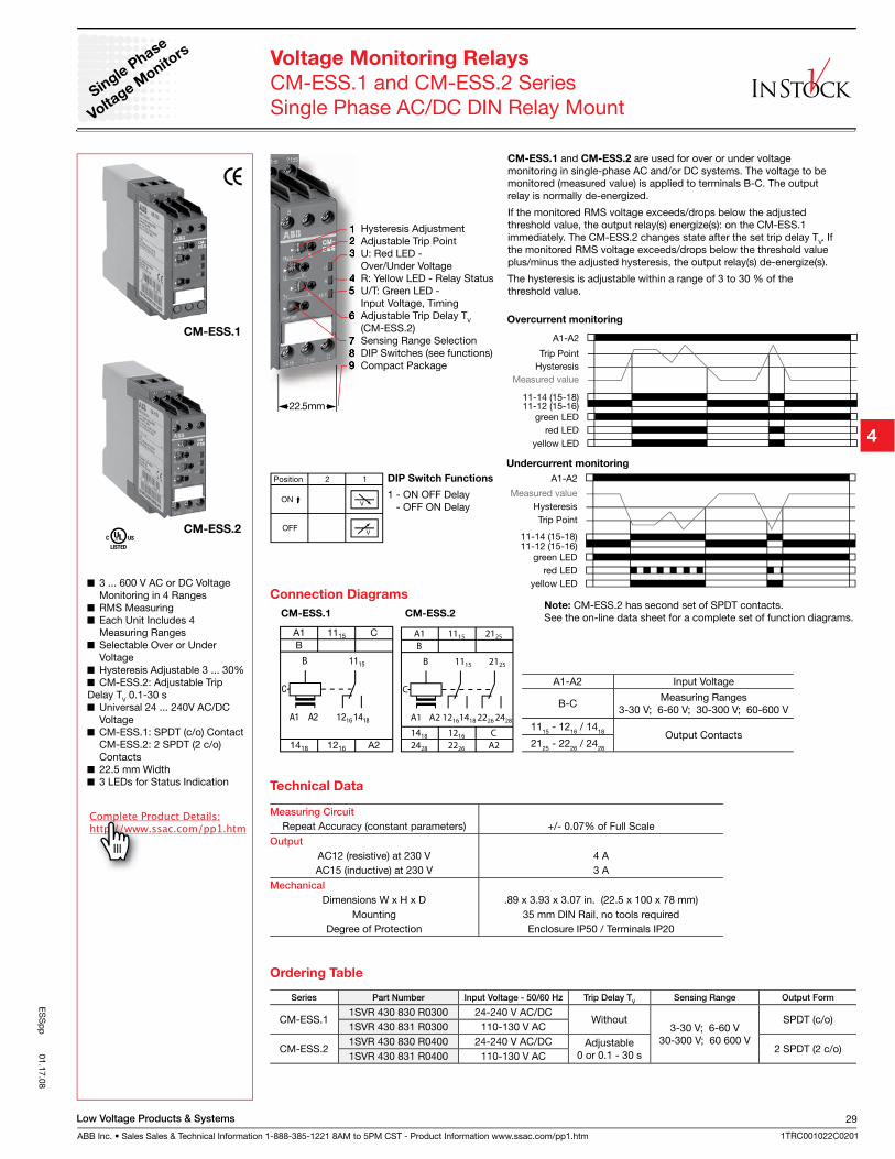
Low Voltage Products & Systems
ABB Inc. • Sales Sales & Technical Information 1-888-385-1221 8AM to 5PM CST - Product Information www.ssac.com/pp1.htm
29
1TRC001022C0201
ES
Sp
p 01.17.08
Series Part Number Input Voltage - 50/60 Hz Trip Delay TV
Sensing Range Output Form
CM-ESS.11SVR 430 830 R0300 24-240 V AC/DC
Without3-30 V; 6-60 V
30-300 V; 60 600 V
SPDT (c/o)1SVR 430 831 R0300 110-130 V AC
CM-ESS.21SVR 430 830 R0400 24-240 V AC/DC Adjustable
0 or 0.1 - 30 s2 SPDT (2 c/o)
1SVR 430 831 R0400 110-130 V AC
Ordering Table
Overcurrent monitoring
Undercurrent monitoring
Note: CM-ESS.2 has second set of SPDT contacts.See the on-line data sheet for a complete set of function diagrams.
Measuring Circuit
Repeat Accuracy (constant parameters) +/- 0.07% of Full ScaleOutput
AC12 (resistive) at 230 V 4 AAC15 (inductive) at 230 V 3 A
Mechanical
Dimensions W x H x D .89 x 3.93 x 3.07 in. (22.5 x 100 x 78 mm)Mounting 35 mm DIN Rail, no tools required
Degree of Protection Enclosure IP50 / Terminals IP20
Technical Data
A1 A2
A1 1115
B
A2
1115
12161418
1418 1216
C
B
C
A1 A2
2125
22262428
A1 1115 2125
B
2428 2226 A2
1115
121614181418 1216 C
B
CA1-A2 Input Voltage
B-CMeasuring Ranges
3-30 V; 6-60 V; 30-300 V; 60-600 V
1115 - 1216 / 1418 Output Contacts2125 - 2226 / 2428
Connection Diagrams
CM-ESS.1 CM-ESS.2
Voltage Monitoring Relays
CM-ESS.1 and CM-ESS.2 SeriesSingle Phase AC/DC DIN Relay Mount
CM-ESS.1 and CM-ESS.2 are used for over or under voltage monitoring in single-phase AC and/or DC systems. The voltage to be monitored (measured value) is applied to terminals B-C. The output relay is normally de-energized.
If the monitored RMS voltage exceeds/drops below the adjusted threshold value, the output relay(s) energize(s): on the CM-ESS.1 immediately. The CM-ESS.2 changes state after the set trip delay TV. If the monitored RMS voltage exceeds/drops below the threshold value plus/minus the adjusted hysteresis, the output relay(s) de-energize(s).
The hysteresis is adjustable within a range of 3 to 30 % of the threshold value.
Single
Phase
Voltage M
onitors
CM-ESS.1
CM-ESS.2
1 Hysteresis Adjustment2 Adjustable Trip Point3 U: Red LED - Over/Under Voltage4 R: Yellow LED - Relay Status5 U/T: Green LED - Input Voltage, Timing6 Adjustable Trip Delay TV
(CM-ESS.2)7 Sensing Range Selection8 DIP Switches (see functions)9 Compact Package
3 ... 600 V AC or DC Voltage Monitoring in 4 Ranges
RMS Measuring Each Unit Includes 4
Measuring Ranges Selectable Over or Under
Voltage Hysteresis Adjustable 3 ... 30% CM-ESS.2: Adjustable Trip
Delay TV 0.1-30 s Universal 24 ... 240V AC/DC
Voltage CM-ESS.1: SPDT (c/o) Contact
CM-ESS.2: 2 SPDT (2 c/o) Contacts
22.5 mm Width 3 LEDs for Status Indication
DIP Switch Functions
1 - ON OFF Delay - OFF ON Delay
22.5mm
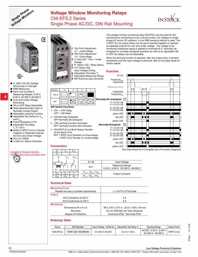
ABB Inc. • Sales Sales & Technical Information 1-888-385-1221 8AM to 5PM CST - Product Information www.ssac.com/pp1.htm
Low Voltage Products & Systems30
1TRC001022C0201
EFS
pp
01.
14.0
8
Voltage Window Monitoring Relays
CM-EFS.2 SeriesSingle Phase AC/DC, DIN Rail Mounting
The voltage window monitoring relay CM-EFS.2 can be used for the simultaneous monitoring of over (>U) and under (<U) voltages in single-phase AC and/or DC systems. A true RMS sensing method is used. The 2 SPDT (2 c/o) output relays can be set to transfer together or operate as separate outputs for over and under voltage. The voltage to be monitored (measured value) is applied to terminals B-C. Normally de-energized or normally energized operation as well as an adjustable ON or OFF trip delays can be selectable.
When the latching function is selected, after the output trips, it remains transferred until the input voltage is removed. See on-line data sheet for further details.
Series Part Number Input Voltage - 50/60 Hz Adjustable Trip Delay TV
Sensing Range Output Form
CM-EFS.2 1SVR 430 750 R0400 24-240 V AC/DC 0 or 0.1-30 sAC/DC: 3-30 V; 6-60 V
30-300 V; 60 600 VSPDT (c/o)
Ordering Table
Measuring Circuit
Repeat Accuracy (constant parameters) +/- 0.07% of Full ScaleOutput
AC12 (resistive) at 230 V 4 AAC15 (inductive) at 230 V 3 A
Mechanical
Dimensions W x H x D .89 x 3.93 x 3.07 in. (22.5 x 100 x 78 mm)Mounting 35 mm DIN Rail, No Tools Required
Degree of Protection Enclosure IP50 / Terminals IP20
Technical Data
See Data Sheet for A Complete Set of Function Diagrams
closed
open
2x1 c/o
1x2 c/o
Position 4 123
ON
OFF
A1 A2
2125
22262428
A1 1115 2125
B
2428 2226 A2
1115
121614181418 1216 C
B
CA1-A2 Input Voltage
B-CMeasuring Range:
3-30 V; 6-60 V; 30-300 V; 60-600 V
1115 - 1216 / 1418 Output Contacts2116 - 2226 / 2428
DIP Switch Functions
1 - ON = OFF Delay - OFF = ON Delay
2 - ON Normally Energized OFF Normally De-energized
3 - ON Latching Function Activated OFF Latching Function Not Activated
4 - ON DPDT (2 c/o) Both Relays Transfer at the Same Time OFF 1 SPDT (c/o) Transfers on Overvoltage, 1 SPDT (c/o) Transfer on Undervoltage
Connection
1 Trip Point Adjustment >U - undervoltage2 Trip Point Adjustment >U - Overvoltage3 U: Red LED - Over / Under Voltage4 R: Yellow LED - Relay Status5 U/T: Green LED - Input Voltage,Timing6 Adjustable Trip Delay TV
7 Selectable Measuring Range8 DIP Switches (see functions)
3...600 V DC/AC Voltage Monitoring in 4 Ranges
RMS Measuring Each Unit Includes 4
Measuring Ranges: 3-30 V; 6-60 V; 30-300 V; 60-600 V
Over and Under Voltage Monitoring
ON or OFF Delay Selectable Selectable Normally Open or
Normally Closed Output Selectable Latching Function Adjustable Trip Points for Vmin
and Vmax
Fixed Hysteresis of 5% Adjustable Trip Delay
TV 0.1-30 s Select 2 SPDT (c/o) to Transfer
Together or Separate Outputs for Over and Under Voltage
22.5 mm Width 3 LEDs for Status Indication
Single
Phase
Voltage M
onitors
Function
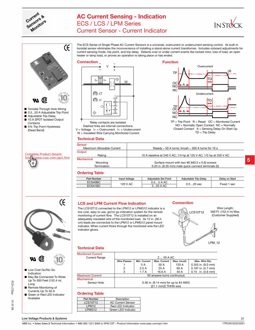
Low Voltage Products & Systems
ABB Inc. • Sales Sales & Technical Information 1-888-385-1221 8AM to 5PM CST - Product Information www.ssac.com/pp1.htm
31
1TRC001022C0201
EC
S-LC
Sp
p 01.07.08
Current
Sensors &
Monito
rs
Toroidal Through Hole Wiring 0.5...20 A Adjustable Trip Point Adjustable Trip Delay 10 A SPDT Isolated Output
Contacts 5% Trip Point Hysteresis
(Dead Band)
AC Current Sensing - Indication
ECS / LCS / LPM SeriesCurrent Sensor - Current Indicator
The ECS Series of Single Phase AC Current Sensors is a universal, overcurrent or undercurrent sensing control. Its built-in toroidal sensor eliminates the inconvenience of installing a stand-alone current transformer. Includes onboard adjustments for current sensing mode, trip point, and trip delay. Detects over or under current events like locked rotor, loss of load, an open heater or lamp load, or proves an operation is taking place or has ended.
Function
TP = Trip Point R = Reset OC = Monitored CurrentNO = Normally Open Contact NC = Normally
Closed Contact A = Sensing Delay On Start UpTD = Trip Delay
Overcurrent
Undercurrent
Connection
Relay contacts are isolated.Dashed lines are internal connections.
V = Voltage I> = Overcurrent I< = UndercurrentW = Insulated Wire Carrying Monitored Current
SensorMaximum Allowable Current Steady – 50 A turns; Inrush – 300 A turns for 10 s
OutputRating 10 A resistive at 240 V AC; 1/4 hp at 125 V AC; 1/2 hp at 250 V AC
Mechanical
Mounting Surface mount with two #6 (M3.5 x 0.6) screwsTermination 0.25 in. (6.35 mm) male quick connect terminals (5)
Part Number Input Voltage Adjustable Set Point Adjustable Trip Delay Delay on Start
ECS40BC120 V AC
0.5…5 A AC0.5…20 sec Fixed 1 sec
ECS41BC 2...20 A AC
Low Cost Go/No Go Indication
May Be Connected To Wires Up To 500 Feet (152.4 m) Long
Remote Monitoring of Currents Up To 50 A
Green or Red LED Indicator Available
LCS and LPM Current Flow Indication
The LCS10T12 connected to the LPM12 or LPMG12 indicator is a low cost, easy to use, go/no go indication system for the remote monitoring of current flow. The LCS10T12 is installed on an adequately insulated wire of the monitored load. Its 12 in. (30.4 cm) leads are connected to the LPM12 or LPMG12 panel mount indicator. When current flows through the monitored wire the LED indicator glows.
Connection
Wire Length:500 Ft. (152.4 m) Max.(Customer Supplied)
Ordering Table
Technical Data
Monitored Current
Current Range 2 ... 50 A ACWire Passes Min. Current Max. Current Max. Inrush Max. Wire Dia.
1 5 A 50 A 120 A 0.355 in. (9.0 mm)2 2.5 A 25 A 60 A 0.187 in. (4.7 mm)3 1.7 A 16.6 A 40 A 0.15 in. (3.8 mm)
Maximum Current 50 ampere-turns continuousMechanical
Sensor Hole 0.36 in. (9.14 mm) for up to #4 AWG(21.1 mm2) THHN wire
Part Number Description
LCS10T12 AC Current SensorLPM12 Red LED Indicator
LPMG12 Green LED Indicato
Technical Data
Ordering Table
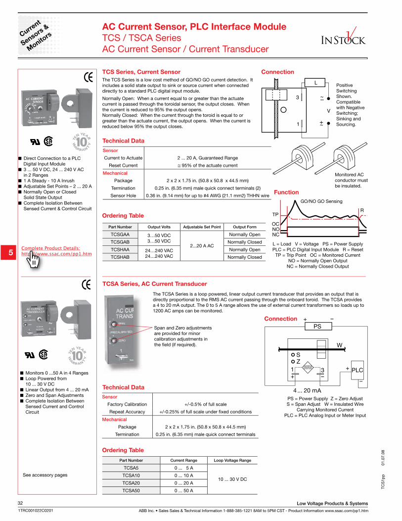
ABB Inc. • Sales Sales & Technical Information 1-888-385-1221 8AM to 5PM CST - Product Information www.ssac.com/pp1.htm
Low Voltage Products & Systems32
1TRC001022C0201
Direct Connection to a PLC Digital Input Module
3 ... 50 V DC, 24 ... 240 V AC in 2 Ranges
1 A Steady - 10 A Inrush Adjustable Set Points – 2 ... 20 A Normally Open or Closed
Solid State Output Complete Isolation Between
Sensed Current & Control Circuit
Function
L = Load V = Voltage PS = Power SupplyPLC = PLC Digital Input Module R = Reset
TP = Trip Point OC = Monitored Current NO = Normally Open Output
NC = Normally Closed Output
GO/NO GO Sensing
TCS Series, Current Sensor
The TCS Series is a low cost method of GO/NO GO current detection. It includes a solid state output to sink or source current when connected directly to a standard PLC digital input module.
Normally Open: When a current equal to or greater than the actuate current is passed through the toroidal sensor, the output closes. When the current is reduced to 95% the output opens.Normally Closed: When the current through the toroid is equal to or greater than the actuate current, the output opens. When the current is reduced below 95% the output closes.
Connection
Positive Switching Shown. Compatible with Negative Switching; Sinking and Sourcing.
Monitored AC conductor must be insulated.
Technical Data
Current
Sensors &
Monito
rsAC Current Sensor, PLC Interface Module
TCS / TSCA SeriesAC Current Sensor / Current Transducer
Sensor
Current to Actuate 2 ... 20 A, Guaranteed Range
Reset Current 95% of the actuate current
Mechanical
Package 2 x 2 x 1.75 in. (50.8 x 50.8 x 44.5 mm)
Termination 0.25 in. (6.35 mm) male quick connect terminals (2)
Sensor Hole 0.36 in. (9.14 mm) for up to #4 AWG (21.1 mm2) THHN wire
Part Number Output Volts Adjustable Set Point Output Form
TCSGAA 3…50 VDC3…50 VDC
2...20 A AC
Normally Open
TCSGAB Normally Closed
TCSHAA 24…240 VAC24…240 VAC
Normally Open
TCSHAB Normally Closed
The TCSA Series is a loop powered, linear output current transducer that provides an output that is directly proportional to the RMS AC current passing through the onboard toroid. The TCSA provides a 4 to 20 mA output. The 0 to 5 A range allows the use of external current transformers so loads up to 1200 AC amps can be monitored.
Monitors 0 ...50 A in 4 Ranges Loop Powered from
10 ... 30 V DC Linear Output from 4 ... 20 mA Zero and Span Adjustments Complete Isolation Between
Sensed Current and Control Circuit
Connection
PS
PS = Power Supply Z = Zero Adjust S = Span Adjust W = Insulated Wire
Carrying Monitored Current PLC = PLC Analog Input or Meter Input
See accessory pages
Ordering Table
Sensor
Factory Calibration +/-0.5% of full scale
Repeat Accuracy +/-0.25% of full scale under fixed conditions
Mechanical
Package 2 x 2 x 1.75 in. (50.8 x 50.8 x 44.5 mm)
Termination 0.25 in. (6.35 mm) male quick connect terminals
Technical Data
Ordering Table
Part Number Current Range Loop Voltage Range
TCSA5 0 ... 5 A
10 ... 30 V DCTCSA10 0 ... 10 A
TCSA20 0 ... 20 A
TCSA50 0 ... 50 A
TCS
1pp
01.
07.0
8
Span and Zero adjustments are provided for minor calibration adjustments in the field (if required).
TCSA Series, AC Current Transducer
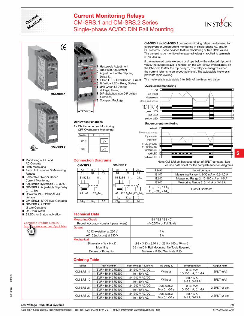
Low Voltage Products & Systems
ABB Inc. • Sales Sales & Technical Information 1-888-385-1221 8AM to 5PM CST - Product Information www.ssac.com/pp1.htm
33
1TRC001022C0201
SR
Sp
p 01.14.08
CM-SRS.1
CM-SRS.2
1 Hysteresis Adjustment2 Trip Point Adjustment3 Adjustment of the Tripping Delay TV
4 I: Red LED - Over/Under Current5 R: Yellow LED - Relay Status6 U/T: Green LED Input Voltage, Timing7 DIP Switches (see DIP switch functions)8 Compact Package
Monitoring of DC and AC Currents
RMS Measuring Each Unit Includes 3 Measuring
Ranges Selectable Over or Under
Current Monitoring Adjustable Hysteresis 3 ... 30% CM-SRS.2: Adjustable Trip Delay
0.1 ... 30s Universal 24 ... 240V AC/DC
Voltage CM-SRS.1: SPDT (c/o) Contacts CM-SRS.2: 2 SPDT
(2 c/o) Contacts 22.5 mm Width 3 LEDs for Status Indication
Current Monitoring Relays
CM-SRS.1 and CM-SRS.2 SeriesSingle-phase AC/DC DIN Rail Mounting
Current
Monito
rs
Overcurrent monitoring
Undercurrent monitoring
CM-SRS.1 and CM-SRS.2 current monitoring relays can be used for overcurrent or undercurrent monitoring in single-phase AC and/or DC systems. These devices feature monitoring of true RMS values. The current to be monitored (measured value) is applied to terminals B1/B2/B3-C.
If the measured value exceeds or drops below the selected trip point value, the output relay(s) energize: on the CM-SRS.1 immediately, on the CM-SRS.2 after the trip delay TV. The relay de-energizes when the current returns to an acceptable level. The adjustable hysteresis prevents rapid cycling.
The hysteresis is adjustable 3 to 30% of the threshold value.
Note: CM-SRS.2x has second set of SPDT contacts. See on-line data sheet for the complete function diagrams
Series Part Number Input Voltage - 50/60 Hz Trip Delay TV
Sensing Range Output Form
CM-SRS.111SVR 430 840 R0200 24-240 V AC/DC
Without3-30 mA;
10-100 mA; 0.1-1ASPDT (c/o)
1SVR 430 841 R0200 110-130 V AC
CM-SRS.121SVR 430 840 R0300 24-240 V AC/DC
Without0.3-1.5 A;
1-5 A; 3-15 ASPDT (c/o)
1SVR 430 841 R0300 110-130 V AC
CM-SRS.211SVR 430 840 R0400 24-240 V AC/DC Adjustable
0 or 0.1-30 s3-30 mA;
10-100 mA; 0.1-1A2 SPDT (2 c/o)
1SVR 430 841 R0400 110-130 V AC
CM-SRS.221SVR 430 840 R0500 24-240 V AC/DC Adjustable
0 or 0.1-30 s0.3-1.5 A;
1-5 A; 3-15 A2 SPDT (2 c/o)
1SVR 430 841 R0500 110-130 V AC
Ordering Table
A1 A2
A1 1115
B1 B2 B3
A2
1115
12161418
1418 1216
C
B1 B2 B3
C
CM-SRS.1
A1 A2
2125
22262428
A1 1115 2125
B1 B2 B3
2428 2226 A2
1115
121614181418 1216 C
B1 B2 B3
C
A1-A2 Input VoltageB1-C Measuring Range 1: 3-30 mA or 0.3-1.5 AB2-C Measuring Range 2: 10-100 mA or 1-5 AB3-C Measuring Range 3: 0.1-1 A or 3-15 A
1115 - 1216 / 1418 Output Contacts2125 - 2226 / 2428
Connection Diagrams
CM-SRS.2
DIP Switch Functions
1 - ON Undercurrent Monitoring - OFF Overcurrent Monitoring
Measuring Circuit B1 / B2 / B3 - CRepeat Accuracy (constant parameters) +/- 0.07% of Full Scale
Output
AC12 (resistive) at 230 V 4 AAC15 (inductive) at 230 V 3 A
Mechanical
Dimensions W x H x D .89 x 3.93 x 3.07 in. (22.5 x 100 x 78 mm)Mounting 35 mm DIN Rail Mounting, No Tools Required
Degree of Protection Enclosure IP50 / Terminals IP20
Technical Data
22.5mm
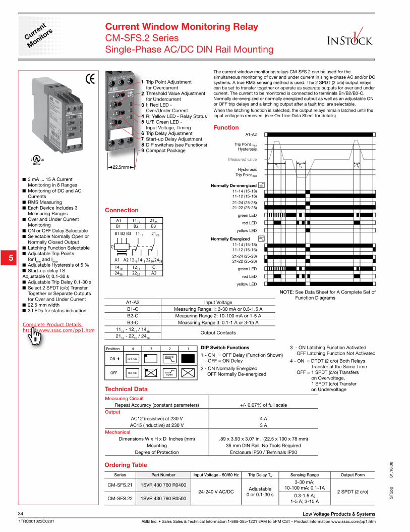
ABB Inc. • Sales Sales & Technical Information 1-888-385-1221 8AM to 5PM CST - Product Information www.ssac.com/pp1.htm
Low Voltage Products & Systems34
1TRC001022C0201
SFS
pp
01.
16.0
8
Series Part Number Input Voltage - 50/60 Hz Trip Delay TV
Sensing Range Output Form
CM-SFS.21 1SVR 430 760 R040024-240 V AC/DC
Adjustable0 or 0.1-30 s
3-30 mA;10-100 mA; 0.1-1A
2 SPDT (2 c/o)CM-SFS.22 1SVR 430 760 R0500
0.3-1.5 A; 1-5 A; 3-15 A
Ordering Table
Normally De-energized
Normally Energized
Function
1 Trip Point Adjustment for Overcurrent2 Threshold Value Adjustment for Undercurrent3 I: Red LED - Over/Under Current4 R: Yellow LED - Relay Status5 U/T: Green LED - Input Voltage, Timing6 Trip Delay Adjustment7 Start-up Delay Adjustment8 DIP switches (see Functions)9 Compact Package
3 mA ... 15 A Current Monitoring in 6 Ranges
Monitoring of DC and AC Currents
RMS Measuring Each Device Includes 3
Measuring Ranges Over and Under Current
Monitoring ON or OFF Delay Selectable Selectable Normally Open or
Normally Closed Output Latching Function Selectable Adjustable Trip Points
for Imin and Imax
Adjustable Hysteresis of 5 % Start-up delay TS
Adjustable 0; 0.1-30 s Adjustable Trip Delay 0.1-30 s Select 2 SPDT (c/o) Transfer
Together or Separate Outputs for Over and Under Current
22.5 mm width 3 LEDs for status indication
Current Window Monitoring Relay
CM-SFS.2 SeriesSingle-Phase AC/DC DIN Rail Mounting
The current window monitoring relays CM-SFS.2 can be used for the simultaneous monitoring of over and under current in single-phase AC and/or DC systems. A true RMS sensing method is used. The 2 SPDT (2 c/o) output relays can be set to transfer together or operate as separate outputs for over and under current. The current to be monitored is connected to terminals B1/B2/B3-C. Normally de-energized or normally energized output as well as an adjustable ON or OFF trip delays and a latching output after a fault trip, are selectable.When the latching function is selected, the output relays remain latched until the input voltage is removed. (see On-Line Data Sheet for details)
Current
Monito
rs
closed
open
2x1 c/o
1x2 c/o
Position 4 123
ON
OFF
A1 A2
2125
22262428
A1 1115 2125
B1 B2 B3
2428 2226 A2
1115
121614181418 1216 C
B1 B2 B3
C
A1-A2 Input VoltageB1-C Measuring Range 1: 3-30 mA or 0.3-1.5 AB2-C Measuring Range 2: 10-100 mA or 1-5 AB3-C Measuring Range 3: 0.1-1 A or 3-15 A
1115 - 1216 / 1418 Output Contacts2116 - 2226 / 2428
DIP Switch Functions
1 - ON = OFF Delay (Function Shown) - OFF = ON Delay
2 - ON Normally Energized OFF Normally De-energized
Connection
3 - ON Latching Function Activated OFF Latching Function Not Activated
4 - ON = DPDT (2 c/o) Both Relays Transfer at the Same Time OFF = 1 SPDT (c/o) Transfers on Overvoltage, 1 SPDT (c/o) Transfer on Undervoltage
Measuring Circuit
Repeat Accuracy (constant parameters) +/- 0.07% of full scaleOutput
AC12 (resistive) at 230 V 4 AAC15 (inductive) at 230 V 3 A
Mechanical
Dimensions W x H x D Inches (mm) .89 x 3.93 x 3.07 in. (22.5 x 100 x 78 mm)Mounting 35 mm DIN Rail, No Tools Required
Degree of Protection Enclosure IP50 / Terminals IP20
Technical Data
NOTE: See Data Sheet for A Complete Set of Function Diagrams
22.5mm
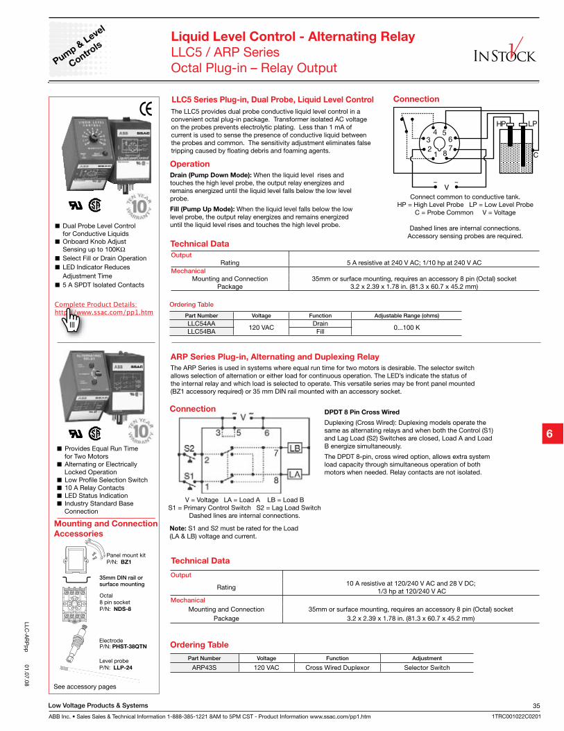
Low Voltage Products & Systems
ABB Inc. • Sales Sales & Technical Information 1-888-385-1221 8AM to 5PM CST - Product Information www.ssac.com/pp1.htm
35
1TRC001022C0201
LLC-A
RP
pp
01.07.08
Liquid Level Control - Alternating Relay
LLC5 / ARP SeriesOctal Plug-in – Relay OutputPum
p & L
evel
Controls
Dual Probe Level Control for Conductive Liquids
Onboard Knob Adjust Sensing up to 100K
Select Fill or Drain Operation LED Indicator Reduces
Adjustment Time 5 A SPDT Isolated Contacts
The LLC5 provides dual probe conductive liquid level control in a convenient octal plug-in package. Transformer isolated AC voltage on the probes prevents electrolytic plating. Less than 1 mA of current is used to sense the presence of conductive liquid between the probes and common. The sensitivity adjustment eliminates false tripping caused by floating debris and foaming agents.
Operation
Drain (Pump Down Mode): When the liquid level rises and touches the high level probe, the output relay energizes and remains energized until the liquid level falls below the low level probe.
Fill (Pump Up Mode): When the liquid level falls below the low level probe, the output relay energizes and remains energized until the liquid level rises and touches the high level probe.
Connection
Mounting and Connection
Accessories
See accessory pages
Connect common to conductive tank.HP = High Level Probe LP = Low Level Probe
C = Probe Common V = Voltage
Dashed lines are internal connections. Accessory sensing probes are required.
OutputRating 5 A resistive at 240 V AC; 1/10 hp at 240 V AC
Mechanical
Mounting and Connection 35mm or surface mounting, requires an accessory 8 pin (Octal) socketPackage 3.2 x 2.39 x 1.78 in. (81.3 x 60.7 x 45.2 mm)
Technical Data
Provides Equal Run Time for Two Motors
Alternating or Electrically Locked Operation
Low Profile Selection Switch 10 A Relay Contacts LED Status Indication Industry Standard Base
Connection
ARP Series Plug-in, Alternating and Duplexing Relay
The ARP Series is used in systems where equal run time for two motors is desirable. The selector switch allows selection of alternation or either load for continuous operation. The LED’s indicate the status of the internal relay and which load is selected to operate. This versatile series may be front panel mounted (BZ1 accessory required) or 35 mm DIN rail mounted with an accessory socket.
DPDT 8 Pin Cross Wired
Duplexing (Cross Wired): Duplexing models operate the same as alternating relays and when both the Control (S1) and Lag Load (S2) Switches are closed, Load A and Load B energize simultaneously.
The DPDT 8-pin, cross wired option, allows extra system load capacity through simultaneous operation of both motors when needed. Relay contacts are not isolated.
V = Voltage LA = Load A LB = Load BS1 = Primary Control Switch S2 = Lag Load Switch
Dashed lines are internal connections.
Connection
Output
Rating10 A resistive at 120/240 V AC and 28 V DC;
1/3 hp at 120/240 V ACMechanical
Mounting and Connection 35mm or surface mounting, requires an accessory 8 pin (Octal) socketPackage 3.2 x 2.39 x 1.78 in. (81.3 x 60.7 x 45.2 mm)
Technical Data
Part Number Voltage Function Adjustable Range (ohms)
LLC54AA120 VAC
Drain0...100 K
LLC54BA Fill
Ordering Table
Part Number Voltage Function Adjustment
ARP43S 120 VAC Cross Wired Duplexor Selector Switch
Ordering Table
LLC5 Series Plug-in, Dual Probe, Liquid Level Control
Note: S1 and S2 must be rated for the Load (LA & LB) voltage and current.
35mm DIN rail or surface mounting
P/N: PHST-38QTN
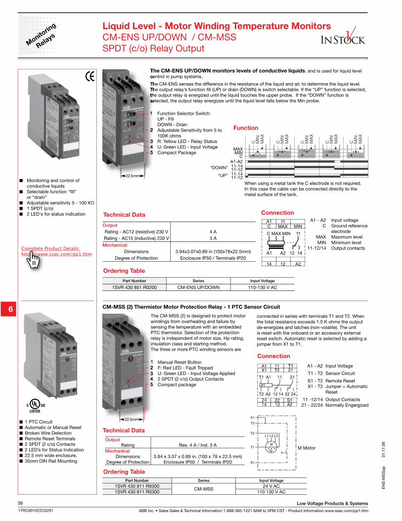
ABB Inc. • Sales Sales & Technical Information 1-888-385-1221 8AM to 5PM CST - Product Information www.ssac.com/pp1.htm
Low Voltage Products & Systems36
1TRC001022C0201
EN
S-M
SS
pp
01.
17.0
8
Liquid Level - Motor Winding Temperature Monitors
CM-ENS UP/DOWN / CM-MSSSPDT (c/o) Relay Output
The CM-ENS UP/DOWN monitors levels of conductive liquids, and is used for liquid level control in pump systems.
The CM-ENS senses the difference in the resistance of the liquid and air, to determine the liquid level. The output relay’s function fill (UP) or drain (DOWN) is switch selectable. If the “UP” function is selected, the output relay is energized until the liquid touches the upper probe. If the “DOWN” function is selected, the output relay energizes until the liquid level falls below the Min probe.
Monito
ring
Relays
MAX
“DOWN”
MINC
A1-A211-1411-12
“UP” 11-1411-12
When using a metal tank the C electrode is not required. In this case the cable can be connected directly to the metal surface of the tank.
Part Number Series Input Voltage
1SVR 430 851 R0200 CM-ENS UP/DOWN 110-130 V AC
Output
Rating - AC12 (resistive) 230 V 4 ARating - AC15 (inductive) 230 V 3 A
Mechanical
Dimensions 3.94x3.07x0.89 in (100x78x22.5mm)Degree of Protection Enclosure IP50 / Terminals IP20
Monitoring and control of conductive liquids
Selectable function “fill” or “drain”
Adjustable sensitivity 5 - 100 KΩ 1 SPDT (c/o) 2 LED‘s for status indication Technical Data
1 Function Selector Switch: UP - Fill DOWN - Drain2 Adjustable Sensitivity from 5 to
100K ohms3 R: Yellow LED - Relay Status4 U: Green LED - Input Voltage5 Compact Package
Ordering Table
1214 A2
CA1
MAX11
MIN
MIN 11MAXC
A2A1 12 14
Connection A1 - A2 Input voltage C Ground reference electrode MAX Maximum level MIN Minimum level 11-12/14 Output contacts
Function
Part Number Series Input Voltage
1SVR 430 811 R9300CM-MSS
24 V AC1SVR 430 811 R0300 110 130 V AC
Ordering Table
1 Manual Reset Button2 F: Red LED - Fault Tripped3 U: Green LED - Input Voltage Applied4. 2 SPDT (2 c/o) Output Contacts5. Compact package
CM-MSS (2) Thermistor Motor Protection Relay - 1 PTC Sensor Circuit
A1 - A2 Input Voltage
T1 - T2 Sensor Circuit
S1 - T2 Remote Reset X1 - T2 Jumper = Automatic Reset
11 -12/14 Output Contacts 21 - 22/24 Normally Engergized
1 PTC Circuit Automatic or Manual Reset Broken Wire Detection Remote Reset Terminals 2 SPDT (2 c/o) Contacts 2 LED’s for Status Indication 22.5 mm wide enclosure, 35mm DIN Rail Mounting
Connection
The CM-MSS (2) is designed to protect motor windings from overheating and failure by sensing the temperature with an embedded PTC thermistor. Selection of the protection relay is independent of motor size, Hp rating, insulation class and starting method. The three or more PTC winding sensors are
connected in series with terminals T1 and T2. When the total resistance exceeds 1.5 K ohms the output de-energizes and latches (non-volatile). The unit is reset with the onboard or an accessory external reset switch. Automatic reset is selected by adding a jumper from X1 to T1.
OutputRating Res. 4 A / Ind. 3 A
Mechanical
Dimensions 3.94 x 3.07 x 0.89 in. (100 x 78 x 22.5 mm)Degree of Protection Enclosure IP50 / Terminals IP20
Technical Data
M Motor
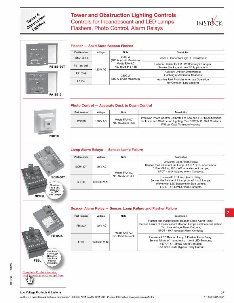
Low Voltage Products & Systems
ABB Inc. • Sales Sales & Technical Information 1-888-385-1221 8AM to 5PM CST - Product Information www.ssac.com/pp1.htm
37
1TRC001022C0201
TWR
pp
01.04.08
Tower and Obstruction Lighting Controls
Controls for Incandescant and LED LampsFlashers, Photo Control, Alarm Relays
Tower &
Obstructio
n
Lightin
g
Part Number Voltage Note Description
FS155-30RF
120 V AC
2500 W(200 A Inrush Maximum)
Meets FAA-AC No. 150/5345-43E
Beacon Flasher for High RF Installations
FS-155-30TBeacon Flasher for FM, TV, Chimneys, Bridges,
Smoke Stacks, and Low RF Applications
FA155-22500 W
(200 A Inrush Maximum)
Auxiliary Unit for Synchronous Flashing of Additional Beacons
FA155Auxiliary Unit Provides Alternate Operation
for Constant Line Loading
Part Number Voltage Note Description
PCR10 120 V ACMeets FAA-AC
No. 150/5345-43E
Precision Photo Control Calibrated to FAA and FCC Specifications for Tower and Obstruction Lighting. Two SPST N.O. 20 A Contacts.
Without Cast Aluminum Housing.
Part Number Voltage Note Description
SCR430T 120 V AC
Meets FAA-AC No. 150/5345-43E
Universal Light Alarm Relay; Senses the Failure of One Lamp Out of 1, 2, 3, or 4 Lamps;
116 or 620 W, 120 V AC Incandescent Lamps;SPDT - 10 A Isolated Alarm Contacts.
SCR9L 120/230 V AC
Universal LED Lamp Alarm Relay;Senses the Failure of 1 Lamp out of 1 to 8 Lamps;
Works with LED Beacons or Side Lamps;1 SPDT & 1 SPNO Alarm Contacts.
Part Number Voltage Note Description
FB120A 120 V AC
Meets FAA-AC No. 150/5345-43E
Flasher and Incandescent Beacon Lamp Alarm Relay;Senses Failure of Incandescent Beacon Lamps and Beacon Flasher;
Two Line Voltage Alarm Outputs; SPDT - 10 A Isolated Alarm Contacts
FB9L 120/230 V AC
Universal LED Beacon Lamp & Flasher Alarm Relay;Senses failure of 1 lamp out of 1 to 8 LED Beacons;
1 SPDT & 1 SPNO Alarm Contacts; 0.5A Solid State Bypass Relay Output
Flasher — Solid State Beacon Flasher
Photo Control — Accurate Dusk to Dawn Control
Lamp Alarm Relays — Senses Lamp Failure
Beacon Alarm Relay — Senses Lamp Failure and Flasher Failure
PCR10
FS155-30T
FA155-2
SCR430T
SCR9L
FB9L
FB120A
Monitors1 to 8 LED Beacons;MonitorsFlasher
Operation
Monitors1 to 8 LEDBeaconsor LED
Side Lamps
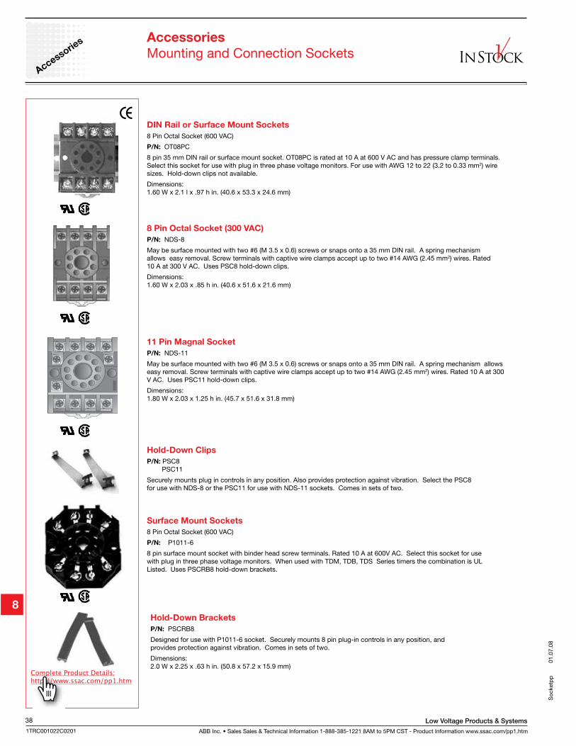
ABB Inc. • Sales Sales & Technical Information 1-888-385-1221 8AM to 5PM CST - Product Information www.ssac.com/pp1.htm
Low Voltage Products & Systems38
1TRC001022C0201
8 Pin Octal Socket (300 VAC)
P/N: NDS-8
May be surface mounted with two #6 (M 3.5 x 0.6) screws or snaps onto a 35 mm DIN rail. A spring mechanism allows easy removal. Screw terminals with captive wire clamps accept up to two #14 AWG (2.45 mm2) wires. Rated 10 A at 300 V AC. Uses PSC8 hold-down clips.
Dimensions:1.60 W x 2.03 x .85 h in. (40.6 x 51.6 x 21.6 mm)
Accessories
Mounting and Connection Sockets
DIN Rail or Surface Mount Sockets
8 Pin Octal Socket (600 VAC)
P/N: OT08PC
8 pin 35 mm DIN rail or surface mount socket. OT08PC is rated at 10 A at 600 V AC and has pressure clamp terminals. Select this socket for use with plug in three phase voltage monitors. For use with AWG 12 to 22 (3.2 to 0.33 mm2) wire sizes. Hold-down clips not available.
Dimensions:1.60 W x 2.1 l x .97 h in. (40.6 x 53.3 x 24.6 mm)
11 Pin Magnal Socket
P/N: NDS-11
May be surface mounted with two #6 (M 3.5 x 0.6) screws or snaps onto a 35 mm DIN rail. A spring mechanism allows easy removal. Screw terminals with captive wire clamps accept up to two #14 AWG (2.45 mm2) wires. Rated 10 A at 300 V AC. Uses PSC11 hold-down clips.
Dimensions:1.80 W x 2.03 x 1.25 h in. (45.7 x 51.6 x 31.8 mm)
Hold-Down Clips
P/N: PSC8 PSC11
Securely mounts plug in controls in any position. Also provides protection against vibration. Select the PSC8 for use with NDS-8 or the PSC11 for use with NDS-11 sockets. Comes in sets of two.
Surface Mount Sockets
8 Pin Octal Socket (600 VAC)
P/N: P1011-6
8 pin surface mount socket with binder head screw terminals. Rated 10 A at 600V AC. Select this socket for use with plug in three phase voltage monitors. When used with TDM, TDB, TDS Series timers the combination is UL Listed. Uses PSCRB8 hold-down brackets.
Hold-Down Brackets
P/N: PSCRB8
Designed for use with P1011-6 socket. Securely mounts 8 pin plug-in controls in any position, and provides protection against vibration. Comes in sets of two.
Dimensions:2.0 W x 2.25 x .63 h in. (50.8 x 57.2 x 15.9 mm)
Soc
ketp
p
0
1.07
.08
Accessories
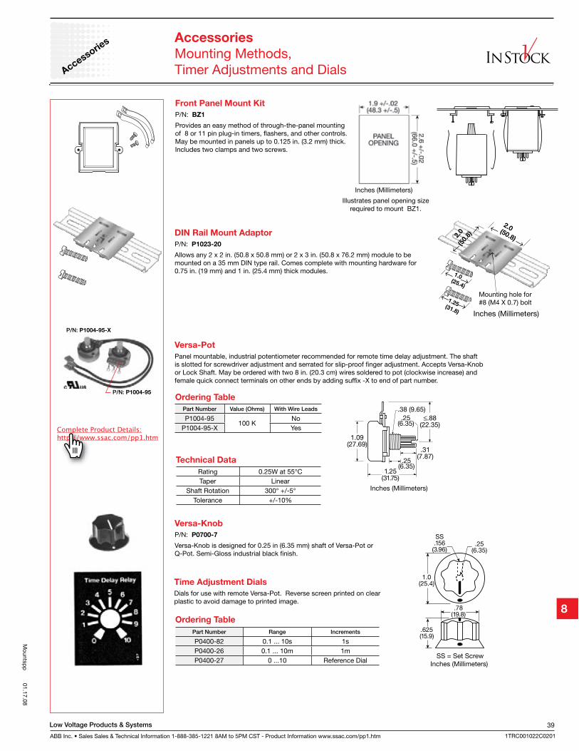
Low Voltage Products & Systems
ABB Inc. • Sales Sales & Technical Information 1-888-385-1221 8AM to 5PM CST - Product Information www.ssac.com/pp1.htm
39
1TRC001022C0201
DIN Rail Mount Adaptor
P/N: P1023-20
Allows any 2 x 2 in. (50.8 x 50.8 mm) or 2 x 3 in. (50.8 x 76.2 mm) module to be mounted on a 35 mm DIN type rail. Comes complete with mounting hardware for 0.75 in. (19 mm) and 1 in. (25.4 mm) thick modules.
1.0(25.4)
1.25(31.8)
2.0
(50.
8)
2.0(50.8)
Mounting hole for#8 (M4 X 0.7) bolt
Inches (Millimeters)
Front Panel Mount Kit
P/N: BZ1
Provides an easy method of through-the-panel mounting of 8 or 11 pin plug-in timers, flashers, and other controls. May be mounted in panels up to 0.125 in. (3.2 mm) thick. Includes two clamps and two screws.
Illustrates panel opening size required to mount BZ1.
Inches (Millimeters)
Versa-Pot
Panel mountable, industrial potentiometer recommended for remote time delay adjustment. The shaft is slotted for screwdriver adjustment and serrated for slip-proof finger adjustment. Accepts Versa-Knob or Lock Shaft. May be ordered with two 8 in. (20.3 cm) wires soldered to pot (clockwise increase) and female quick connect terminals on other ends by adding suffix -X to end of part number.
Technical Data
Inches (Millimeters)
Versa-Knob
P/N: P0700-7
Versa-Knob is designed for 0.25 in (6.35 mm) shaft of Versa-Pot or Q-Pot. Semi-Gloss industrial black finish.
SS = Set Screw Inches (Millimeters)
Time Adjustment Dials
Dials for use with remote Versa-Pot. Reverse screen printed on clear plastic to avoid damage to printed image.
Accessories
Mounting Methods, Timer Adjustments and Dials
Part Number Value (Ohms) With Wire Leads
P1004-95100 K
NoP1004-95-X Yes
Ordering Table
Rating 0.25W at 55°CTaper Linear
Shaft Rotation 300° +/-5°Tolerance +/-10%
Part Number Range Increments
P0400-82 0.1 ... 10s 1sP0400-26 0.1 ... 10m 1mP0400-27 0 ...10 Reference Dial
Ordering Table
Accessories
Mountsp
p 01.17.08
P/N: P1004-95
P/N: P1004-95-X
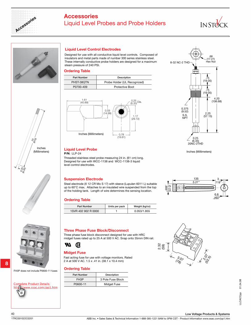
ABB Inc. • Sales Sales & Technical Information 1-888-385-1221 8AM to 5PM CST - Product Information www.ssac.com/pp1.htm
Low Voltage Products & Systems40
1TRC001022C0201
LLC
AC
Cp
p
01.
04.0
8
Accessories
Liquid Level Probes and Probe HoldersAccessorie
s
Steel electrode (X 12 CR Mo S 17) with sleeve (Lupulen 6011 L) suitable up to 60°C max. Attaches to an insulated wire suspended from the top of the holding tank. Length of wire determines the sensing location.
Suspension Electrode
Inches(Millimeters)
Liquid Level Probe
Threaded stainless steel probe measuring 24 in. (61 cm) long. Designed for use with WCC-1138 and WCC-1138-3 liquid level control electrodes.
P/N: LLP-24
Designed for use with all conductive liquid level controls. Composed of insulators and metal parts made of number 300 series stainless steel. These internally conductive probe holders are designed for a maximum steam pressure of 240 PSI.
Liquid Level Control Electrodes
Inches (Millimeters)
Part Number Description
PHST-38QTN Probe Holder (UL Recognized)
P0700-409 Protective Boot
Part Number Units per pack Weight (kg/oz)
1SVR 402 902 R 0000 1 0.053/1.855
Ordering Table
Ordering Table
Three phase fuse block disconnect designed for use with HRC midget fuses rated up to 25 A at 500 V AC. Snap onto 35mm DIN rail.
Three Phase Fuse Block/Disconnect
Midget Fuse
Fast acting fuse for use with voltage monitors. Rated 2 A at 500 V AC. 1.5 x .41 in. (38.1 x 10.4 mm)
Part Number Description
FH3P 3 Pole Fuse Block
P0600-11 Midget Fuse
Ordering TableFH3P does not include P0600-11 fuses
Inches (Millimeters)
3.07(78)
2.07
2.3
2(5
9)
(52.
5)
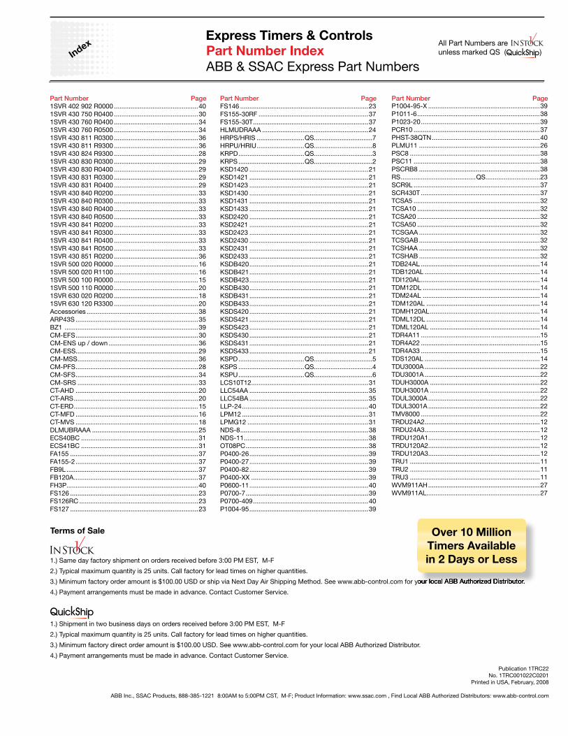
1SVR 402 902 R0000 ..............................................401SVR 430 750 R0400 ..............................................301SVR 430 760 R0400 ..............................................341SVR 430 760 R0500 ..............................................341SVR 430 811 R0300 ..............................................361SVR 430 811 R9300 ..............................................361SVR 430 824 R9300 ..............................................281SVR 430 830 R0300 ..............................................291SVR 430 830 R0400 ..............................................291SVR 430 831 R0300 ..............................................291SVR 430 831 R0400 ..............................................291SVR 430 840 R0200 ..............................................331SVR 430 840 R0300 ..............................................331SVR 430 840 R0400 ..............................................331SVR 430 840 R0500 ..............................................331SVR 430 841 R0200 ..............................................331SVR 430 841 R0300 ..............................................331SVR 430 841 R0400 ..............................................331SVR 430 841 R0500 ..............................................331SVR 430 851 R0200 ..............................................361SVR 500 020 R0000 ..............................................161SVR 500 020 R1100 ..............................................161SVR 500 100 R0000 ..............................................151SVR 500 110 R0000 ..............................................201SVR 630 020 R0200 ..............................................181SVR 630 120 R3300 ..............................................20Accessories .............................................................38ARP43S ...................................................................35BZ1 .........................................................................39CM-EFS ...................................................................30CM-ENS up / down .................................................36CM-ESS ...................................................................29CM-MSS ..................................................................36CM-PFS ...................................................................28CM-SFS ...................................................................34CM-SRS ..................................................................33CT-AHD ...................................................................20CT-ARS ....................................................................20CT-ERD ....................................................................15CT-MFD ...................................................................16CT-MVS ...................................................................18DLMUBRAAA ..........................................................25ECS40BC ................................................................31ECS41BC ................................................................31FA155 ......................................................................37FA155-2 ...................................................................37FB9L ........................................................................37FB120A ....................................................................37FH3P ........................................................................40FS126 ......................................................................23FS126RC .................................................................23FS127 ......................................................................23
Part Number Index
ABB & SSAC Express Part Numbers
FS146 ......................................................................23FS155-30RF ............................................................37FS155-30T ...............................................................37HLMUDRAAA ..........................................................24HRPS/HRIS ..........................QS................................7HRPU/HRIU ..........................QS................................8KRPD ....................................QS................................3KRPS ....................................QS................................2KSD1420 .................................................................21KSD1421 .................................................................21KSD1423 .................................................................21KSD1430 .................................................................21KSD1431 .................................................................21KSD1433 .................................................................21KSD2420 .................................................................21KSD2421 .................................................................21KSD2423 .................................................................21KSD2430 .................................................................21KSD2431 .................................................................21KSD2433 .................................................................21KSDB420 .................................................................21KSDB421 .................................................................21KSDB423 .................................................................21KSDB430 .................................................................21KSDB431 .................................................................21KSDB433 .................................................................21KSDS420 .................................................................21KSDS421 .................................................................21KSDS423 .................................................................21KSDS430 .................................................................21KSDS431 .................................................................21KSDS433 .................................................................21KSPD ....................................QS................................5KSPS ....................................QS................................4KSPU ....................................QS................................6LCS10T12 ................................................................31LLC54AA .................................................................35LLC54BA .................................................................35LLP-24 .....................................................................40LPM12 .....................................................................31LPMG12 ..................................................................31NDS-8 ......................................................................38NDS-11 ....................................................................38OT08PC ...................................................................38P0400-26 .................................................................39P0400-27 .................................................................39P0400-82 .................................................................39P0400-XX ................................................................39P0600-11 .................................................................40P0700-7 ...................................................................39P0700-409 ...............................................................40P1004-95 .................................................................39
P1004-95-X .............................................................39P1011-6 ...................................................................38P1023-20 .................................................................39PCR10 .....................................................................37PHST-38QTN ...........................................................40PLMU11 ..................................................................26PSC8 .......................................................................38PSC11 .....................................................................38PSCRB8 ..................................................................38RS .........................................QS..............................23SCR9L .....................................................................37SCR430T .................................................................37TCSA5 .....................................................................32TCSA10 ...................................................................32TCSA20 ...................................................................32TCSA50 ...................................................................32TCSGAA ..................................................................32TCSGAB ..................................................................32TCSHAA ..................................................................32TCSHAB ..................................................................32TDB24AL .................................................................14TDB120AL ...............................................................14TDI120AL .................................................................14TDM12DL ................................................................14TDM24AL ................................................................14TDM120AL ..............................................................14TDMH120AL ............................................................14TDML12DL ..............................................................14TDML120AL ............................................................14TDR4A11 ...................................... ...........................15TDR4A22 ..................................... ............................15TDR4A33 ..................................... ............................15TDS120AL ...............................................................14TDU3000A ...............................................................22TDU3001A ...............................................................22TDUH3000A ............................................................22TDUH3001A ............................................................22TDUL3000A .............................................................22TDUL3001A .............................................................22TMV8000 .................................................................22TRDU24A2 ...............................................................12TRDU24A3 ...............................................................12TRDU120A1 .............................................................12TRDU120A2 .............................................................12TRDU120A3 .............................................................12TRU1 .......................................................................11TRU2 .......................................................................11TRU3 .......................................................................11WVM911AH .............................................................27WVM911AL ..............................................................27
Index
Part Number Page Part Number Page Part Number Page
ABB Inc., SSAC Products, 888-385-1221 8:00AM to 5:00PM CST, M-F; Product Information: www.ssac.com , Find Local ABB Authorized Distributors: www.abb-control.com
Publication 1TRC22No. 1TRC001022C0201
Printed in USA, February, 2008
Terms of Sale
1.) Same day factory shipment on orders received before 3:00 PM EST, M-F
2.) Typical maximum quantity is 25 units. Call factory for lead times on higher quantities.
3.) Minimum factory order amount is $100.00 USD or ship via Next Day Air Shipping Method. See www.abb-control.com for your local ABB Authorized Distributor.
4.) Payment arrangements must be made in advance. Contact Customer Service.
1.) Shipment in two business days on orders received before 3:00 PM EST, M-F
2.) Typical maximum quantity is 25 units. Call factory for lead times on higher quantities.
3.) Minimum factory direct order amount is $100.00 USD. See www.abb-control.com for your local ABB Authorized Distributor.
4.) Payment arrangements must be made in advance. Contact Customer Service.
Express Timers & ControlsAll Part Numbers are unless marked QS ( )
Sales Information:
ABB Inc.1206 Hatton RoadWichita Falls, TX 76302Telephone 888-385-1221; 940-397-7000Fax 940-397-7085http://www.abb-control.comUSA Technical Help 888-385-1221 option 4, 8:00AM to 5:00PM CST, M-FFind USA ABB Authorized Distributors: www.abb-control.comSSAC Product Information: http://www.ssac.com
Pub
licat
ion
1TR
C22
No.
1TR
C00
1022
C02
01P
rinte
d in
US
A, M
arch
, 200
8
Sales Information (Canada)
ABB Inc.2117 32nd AvenueLachine, Quebec H8T 3J1Canada
TelephoneAtlantic & Quebec Region: 800-567-0283Ontario Region: 866-460-3300Mid-West & Pacific Region: 866-222-8368