Embed Size (px)
Citation preview
Shock Waves (2016) 26:851–857DOI 10.1007/s00193-016-0627-2
TECHNICAL NOTE
Explosive-driven shock wave and vortex ring interactionwith a propane flame
P. M. Giannuzzi1 · M. J. Hargather2 · G. C. Doig3,4
Received: 7 September 2015 / Revised: 22 January 2016 / Accepted: 5 February 2016 / Published online: 29 February 2016© Springer-Verlag Berlin Heidelberg 2016
Abstract Experiments were performed to analyze the inter-action of an explosively driven shock wave and a propaneflame. A 30 g explosive charge was detonated at one end ofa 3-m-long, 0.6-m-diameter shock tube to produce a shockwave which propagated into the atmosphere. A propaneflame source was positioned at various locations outside ofthe shock tube to investigate the effect of different strengthshock waves. High-speed retroreflective shadowgraph imag-ing visualized the shock wave motion and flame response,while a synchronized color camera imaged the flame directly.The explosively driven shock tube was shown to producea repeatable shock wave and vortex ring. Digital streakimages show the shock wave and vortex ring propagationand expansion. The shadowgrams show that the shock waveextinguishes the propane flame by pushing it off of the fuel
Communicated by A. Higgins.
B M. J. [email protected]
P. M. [email protected]
G. C. [email protected]
1 Energetic Materials Research and Testing Center (EMRTC),New Mexico Tech, 801 Leroy Place, Socorro, New Mexico87801, USA
2 Mechanical Engineering Department and EMRTC, NewMexico Tech, 801 Leroy Place, Socorro, New Mexico 87801,USA
3 Aerospace Engineering Department, California PolytechnicState University, 1 Grand Ave, San Luis Obispo, California93407, USA
4 School of Mechanical and Manufacturing Engineering,University of New South Wales, Sydney, NSW 2052,Australia
source. Even a weak shock wave was found to be capable ofextinguishing the flame.
Keywords Shadowgraph · Vortex ring · Flame extinguish-ment · Explosive shock wave · Flow visualization
1 Introduction
Little is known about the interaction of shock waves andhigh-speed vortex rings with turbulent flames in an openatmosphere, despite the use of high explosives to extinguishwild oil and gas well fires [1,2].Wild oil well fires, character-ized by an enormous flow rate of fuel, make extinguishmentdifficult using conventional methods. Explosives—and theflow features they generate—were efficient at extinguishingfires, thus allowing safe human access to stop the flow of fuel.Experiments have documented the ability to extinguish large-scale oil well [3–5] and forest [6] fires with explosives, andanalysis has indicated that the techniques could be broadlysuccessful. However, there has been a lack of satisfactoryevidence of the time-resolvedmechanisms of extinguishmentor differentiation between possible extinguishment scenarioshave not been presented. The exact mechanisms of extin-guishment have thus remained poorly characterized untilrecently [7,8].
Much work has been performed to understand the natureof shock/fuel/flame interactions for propulsion and flamesin channels, including deflagration to detonation transition.These studies, however, tend to be of small scale and almostentirely physically constrained within pipes and combustionchambers [9,10]. A shock generated explosively and allowedto exhaust to the atmosphere from a closed (shock) tube,however, creates external, three-dimensionally propagatingflow features with decaying intensity. The formation of vor-
123
852 P. M. Giannuzzi et al.
tex rings at the exhaust is a signature process and evolvesdifferently in the compressible and incompressible regimes[11,12]. Objects downstream of the shock tube will expe-rience a nominally planar shock front, then a high-speed,high-impulse flow following it (“blast wind”), and finally avortex ring with induced and entrained rotating flows, oftencharacterized further by an embedded shock and additionalvortices [13,14].
Doig et al. [7,8] investigated shock tube-generated sce-narios and found multiple means of flame extinguishmentin small-scale experiments. The shock tube used was com-pressed air driven with a 0.044 by 0.047 m rectangular crosssection. Shock Mach numbers between 1.1 and 1.5 werestudied for their interactions with laminar Bunsen flames atvarious on- and off-axis locations, using high-speed schlierenand limited high-frequency pressure sensing. The schlierenimaging revealed that the passage of the shock itself throughthe flame did not have any immediate appreciable effect onthe flame structure other than a slight compression of theflame (with presumably an increased rate of combustion asa result). The vortex ring and expanding gas jet followingthe shock were determined to be responsible for all observedextinguishments.
Direct vortex interaction with the flame was observedto rotate and disintegrate the flame structure into turbulentincoherence, followed by extinguishment even if the heatremained over the continuing fuel supply. The flame wasextinguished even when significantly (18 burner diameters)off-axis from the vortex path, due to entrainment of fluid bythe vortex ring reaching a critical level of instantaneous angu-lar velocity [15]. The embedded shock and secondary and ter-tiary vortices accompanying the main ring may have had aneffect on the rate of cessation of combustion in the instanceswhere the vortex-induced response was found to be the pri-
mary mechanism of flame extinguishment. It was unclear asto whether the observed phenomena would scale up.
In the present work, visualization and characterization ofsupersonic flow created by an explosively driven shock tube(Friedlander blast profile) interacting with a propane flameapproximately an order of magnitude greater in size than theprevious laboratory studies [16] is presented. The vortex ringproduced in these studies was found to be of little influence inextinguishing the flames in all scenarios tested, and unlike thecompressed air tests there was not a strong, sustained super-sonic central jet. Therefore, the focus here is on the shockwave and the following subsonic “blast wind” as being thefundamental influences on the flame and its extinguishment.
2 Experimental methods
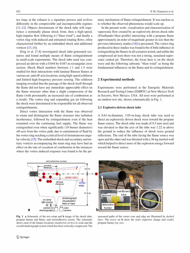
Experiments were performed at the Energetic MaterialsResearch and Testing Center (EMRTC) at NewMexico Techin Socorro, New Mexico, USA. All tests were performed atan outdoor test site, shown schematically in Fig. 1.
2.1 Explosive-driven shock tube
A 0.61-m-diameter, 3.05-m-long shock tube was used todirect an explosively driven shock wave toward the propaneflame source. The shock tube was made of 9.5 mm steel andwas elevated so that the axis of the tube was 1.22 m abovethe ground to reduce the influence of shock wave groundreflections. The end of the tube facing the flame source wasopen and the other end was blocked with a 36-kg inertial wallwhich helped to direct more of the explosion energy forwardtoward the flame source.
Fig. 1 a Schematic of the test setup and b image of the shock tube,propane burner and flame, and retroreflective screen. The schematicshows each of the burner locations (numbered circles) to scale and theoverall shadowgraph systemwhich has been vertically compressed. The
measured paths of the vortex core and edge are illustrated by dashedlines. The insets on b show the (left) explosive charge and (right)propane burner top view
123
Explosive-driven shock wave and vortex ring interaction with a propane flame 853
The explosive charge was a 1.42 m length of 100 graindetcord initiated with an RP-80 detonator, providing 30 g ofPETN explosive. The detcord was tightly wrapped around a0.05-m-diameter cardboard tube, as shown in the left insetof Fig. 1b. The charge was centered along the axis of theshock tube, a distance of 0.20 m from the closed shock tubeend. When positioned further down the shock tube, multipleshock waves were observed exiting, and if placed closer tothe closed end, significant damage occurred to the end wall.Initial experiments showed that the compact detcord wrap-ping, position of the explosive charge, and the length of theshock tube were sufficient to result in a single, nearly planarshock wave exiting the shock tube.
Three 345 kPa PCB model 137B23 blast pressure pen-cil gages were used to record free-field static pressures at500 kHz during the tests. These gages were mounted on theburner stand, above the flame base, with a clear line of sightto the shock tube exit. Separate tests were performed withpressure gages and no flame (P) and flame tests with no pres-sure gages (F). The gages recorded the shockwave pressures,which demonstrated the repeatability of the shock wave peakpressure and exponential decay towithin the gage uncertaintyof ±3 kPa.
2.2 Propane flame source
A commercial propane ring burner, shown in Fig. 1b rightinset, was used as the flame source in these tests. The burnerhad a 0.38-m outer diameter. 1.2-mm-diameter propane ejec-tion holes were distributed across the 0.30-m-diameter innerring (24 holes) and three support arms in a “Y” pattern(40 holes) across the middle of the burner. The burner wasmounted such that the top surface of the burner was at thesame height as the bottom of the shock tube. Commercialpropane was fed from a regulator set at 69 kPa (gage).
2.3 Retroreflective shadowgraph imaging
Aretroreflective shadowgraph system [17]was used to imagethe shockwave andflame interactions. Shadowgraphyvisual-izes shockwaves and turbulent eddies clearly, but is incapableof revealing the expansion behind the shock wave or anyquantitative density measurements [18]. The 4.88-m-long by2.44-m-high retroreflective screen was positioned so that theshock tube axis was centered on the vertical height of thescreen and the open end of the shock tube was at the edge ofthe field of view. A Newport-Oriel 1000 W arc lamp sourcewas focused onto a 45◦ rod mirror mounted in front of thecamera lens to provide illumination [17]. A Photron SA-X2high-speed digital camera recorded images at 20,000 framesper second, 1024 by 672 pixel resolution, and 1 µs exposurefor all tests. The camera and light source were elevated on atable to be at the same height as the shock tube centerline.
A Phantom v611 recorded simultaneous color high-speedimages of the tests at 20,000 frames per second, 768 by 384pixel resolution, and 49 µs exposure. This camera was usedto correlate the time of flame extinguishment with the shockmotion from the shadowgraph images.
3 Experimental results
Table 1 summarizes the tests performed here. The test loca-tions were chosen to include locations: on the axis of theshock tube, along the expected path of the vortex ring, nearthe vortex ring outer edge (near expected entrainment loca-tions), and far from the vortex ring path. The shadowgraphimaging showed that the shock propagation was the samefor all tests up until the interaction with the flame source.Tests validated that the shock propagation and pressurefield were highly repeatable. Outdoor test conditions variedslightly in atmospheric temperature (274–285 K), pressure
Table 1 Summary of testsperformed
Test Position Off-axis distance (m) On-axis distance (m) Radial distance (m) Test type
1, 2 1 0 2.63 2.63 P, P
3, 4 1 0 2.63 2.63 F, F
5, 6 2 0 0.82 0.82 P, F
7, 8 3 2.44 2.63 3.59 P, F
9, 10 4 0.42 1.73 1.78 P, F
11, 12 5 0.42 0.82 0.92 P, F
13, 14 6 0.86 0.32 0.92 P, F
15, 16 7 1.03 1.73 2.01 P, F
17, 18 8 1.03 1.38 1.72 P, P
19, 20 8 1.03 1.38 1.72 F, F
21 9 0.76 7.81 7.85 F
123
854 P. M. Giannuzzi et al.
(102± 5 kPa), and wind (which was less than 5 m/s), but theflame attachment and response were not found to be affected.All calculations of Mach number were made using the tem-perature at the individual test time.
3.1 Shock wave propagation
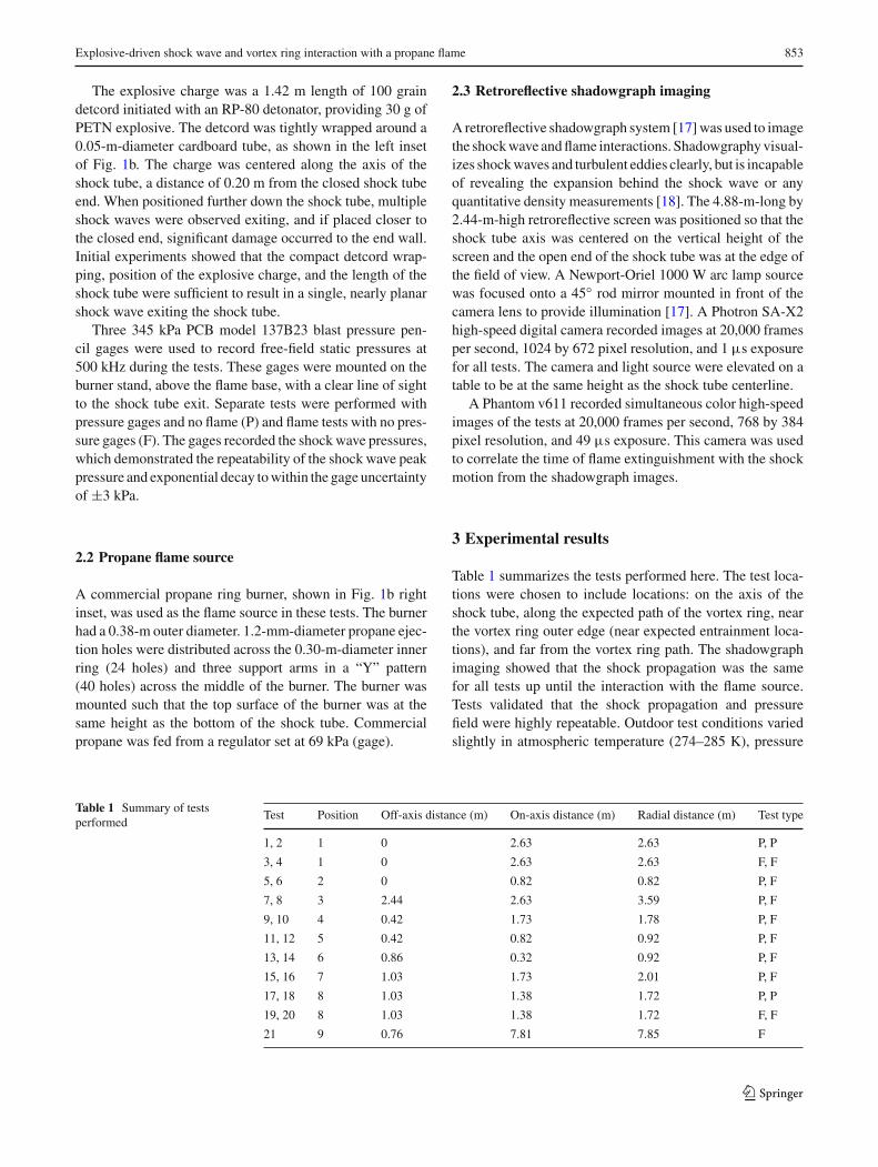
A sequence of images from test 10 is shown in Fig. 2. Theimages show the shock wave emerging from the shock tubeand propagating spherically downstream. The air within theshock tube, which has been accelerated by the shock wave,exits and forms a large vortex ring which grows as it prop-agates downstream. The shock wave impinges on the flamesource and pushes the flame downstream and eventually offthe burner. When the flame moves off the burner, it extin-guishes. The flame is extinguished as the vortex ring arrivesat the burner location, but the vortex has not directly inter-acted with the flame. This can be observed in the final imageof Fig. 2where the thermal plume from the now-extinguishedflame is still to the right of the leading edge of the vortex ring,with no apparent mixing at this point. This extinguishmentmethod was observed in all of the tests reported, other thantest 21 (position 9) in which the flame was not extinguished.
The shock wave ground reflection is clearly observed inFig. 2 at t∗ = 2.9 and t∗ = 4.4. In the analysis of the high-speed images, the reflected shock wave is extremely weakand does not appear to affect the flame in any noticeable way(no motion of the flame or lift-off).
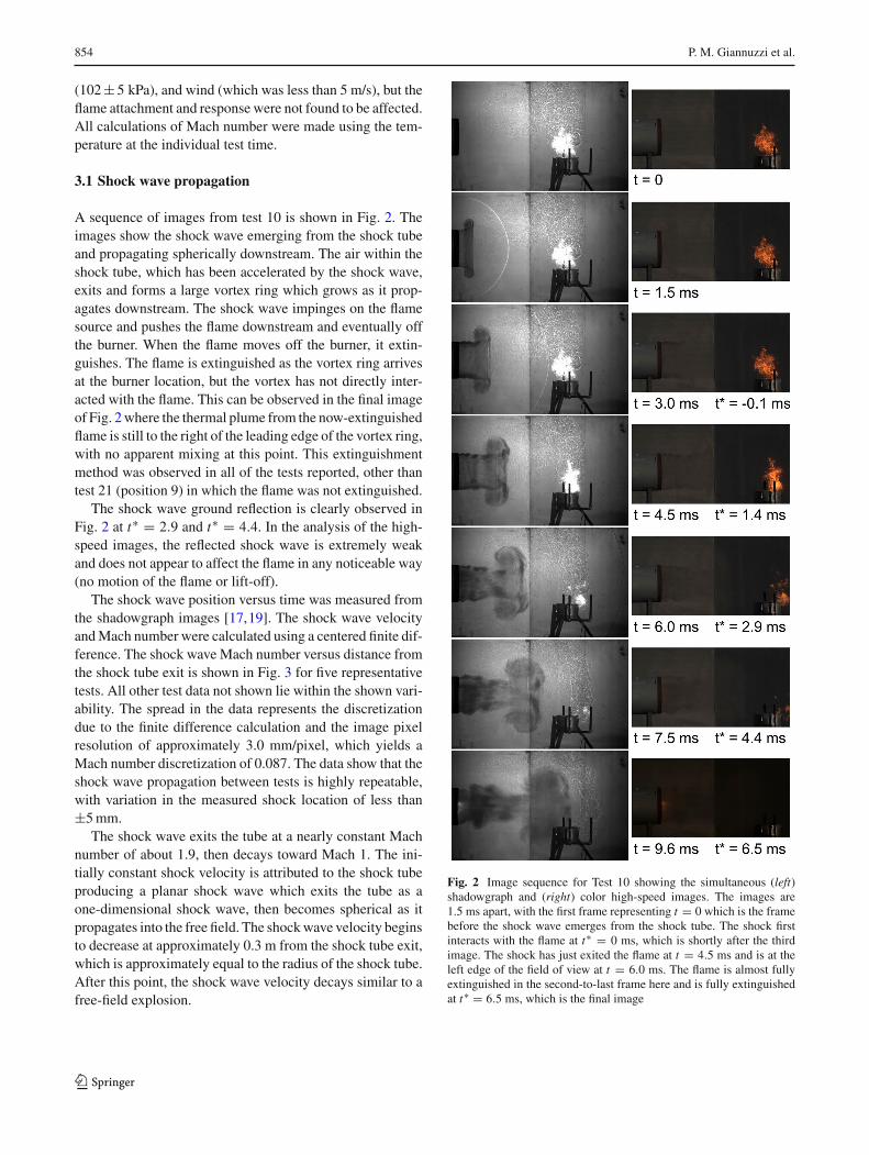
The shock wave position versus time was measured fromthe shadowgraph images [17,19]. The shock wave velocityandMach number were calculated using a centered finite dif-ference. The shock wave Mach number versus distance fromthe shock tube exit is shown in Fig. 3 for five representativetests. All other test data not shown lie within the shown vari-ability. The spread in the data represents the discretizationdue to the finite difference calculation and the image pixelresolution of approximately 3.0 mm/pixel, which yields aMach number discretization of 0.087. The data show that theshock wave propagation between tests is highly repeatable,with variation in the measured shock location of less than±5mm.
The shock wave exits the tube at a nearly constant Machnumber of about 1.9, then decays toward Mach 1. The ini-tially constant shock velocity is attributed to the shock tubeproducing a planar shock wave which exits the tube as aone-dimensional shock wave, then becomes spherical as itpropagates into the free field. The shockwave velocity beginsto decrease at approximately 0.3 m from the shock tube exit,which is approximately equal to the radius of the shock tube.After this point, the shock wave velocity decays similar to afree-field explosion.
Fig. 2 Image sequence for Test 10 showing the simultaneous (left)shadowgraph and (right) color high-speed images. The images are1.5 ms apart, with the first frame representing t = 0 which is the framebefore the shock wave emerges from the shock tube. The shock firstinteracts with the flame at t∗ = 0 ms, which is shortly after the thirdimage. The shock has just exited the flame at t = 4.5 ms and is at theleft edge of the field of view at t = 6.0 ms. The flame is almost fullyextinguished in the second-to-last frame here and is fully extinguishedat t∗ = 6.5 ms, which is the final image
123
Explosive-driven shock wave and vortex ring interaction with a propane flame 855
Fig. 3 Graph of shock wave Mach number versus distance from theshock tube exit. The symbols along the top of the graph show the burnerlocations tested
The experimental data for the shock position, after a dis-tance of 0.3 m from the shock tube exit, were fit using aleast-squares regression to the equation proposed by Deweyfor the shock wave radius (R) versus time (t) for a free airblast [20]:
R = A + Ba0t + C ln (1 + a0t) + D√ln (1 + a0t). (1)
The resulting coefficients were: A = −0.354, B = 1,C = −0.399, D = 1.343, and the parameter a0 = 340 m/s.The curve, plotted in Fig. 3, approximates the shock wavevelocity decay well, which is expected once the shock wavebecomes spherical. The curve fit is used to calculate the shockwave Mach number at each burner location in Table 2. Theradial distance in Tables 1 and 2 represents the straight linedistance from the center of the shock tube exit plane to theburner.
The color high-speed videos were analyzed to estimatethe amount of time from when the shock wave initially con-tacts the flame to when the flame is completely extinguished.The results in Table 2 show that the flame is generally extin-guished faster when the Mach number of the shock wave is
higher. The flame is also extinguished faster if it is on axiswith the shock tube. The uncertainty in the flame extinguish-mentmeasurements is estimated to be±0.25 (5 frames) fromthe manual inspection of images.
The gas velocity behind the shock wave, vg in Table 2,is calculated at each burner location using the Mach numberand simple gas dynamic relationships. For all tests, excepttest 21, the calculated gas velocity is in excess of 50 m/s,which explains why the flame is observed to be blown side-ways off of the burner and thus extinguished. The error inthe air velocity calculation scales with the square of Machnumber and is approximately±25m/s for the values given inTable 2, based on the uncertainty in theMach number at eachlocation. This error is relatively large due to the pixel resolu-tion and resulting error in calculating shock wave velocitiesusing the finite difference method. This calculated velocity isthe instantaneous velocity behind the shock wave. The aver-age velocity that the flame experiences will be lower becausethe pressure behind the shockwave decays exponentially andthe shock wave itself is decelerating.
For test 21, in which the flame was not extinguished, theflame source was almost 8 m from the shock tube exit andthe shockwaveMach numberwas nearly sonic; therefore, thefollowing air had almost no momentum and did not push theflameoff the burner. The upper portion of the flamewas extin-guished, but the lower portion remained attached to the burnerand eventually re-established the full flame. The flame mayhave remained attached at the base because it was slightlyprotected by the burner lip.
3.2 Vortex ring propagation
The high-speed images of the vortex ring showed that it wasa compressible vortex ring, as evidenced by the embeddedshock wave and inward bow shock [14]. While there is sig-nificant shear layer instability, there does not appear to beany clear emergent counter-rotating vortex or vortices aheadof the main vortex ring. These were observed in the small-scale tests of Doig et al. [8] and could be expected at Mach>1.6 exit velocity with a compressed air driver [14], but
Table 2 Time from initial shock interaction with flame and extinguishment
Test Position Radial distance (m) Off-axis distance (m) Mach # Extinguish time, t∗ (ms) velocity gas, vg (m/s)
6 2 0.82 0 1.48 3.6 224
12 5 0.92 0.42 1.42 3.8 199
14 6 0.92 0.86 1.42 5.0 199
19 8 1.72 1.03 1.19 6.5 97
10 4 1.78 0.42 1.18 6.5 93
16 7 2.01 1.03 1.15 10.0 78
3 1 2.63 0 1.10 8.0 53
123
856 P. M. Giannuzzi et al.
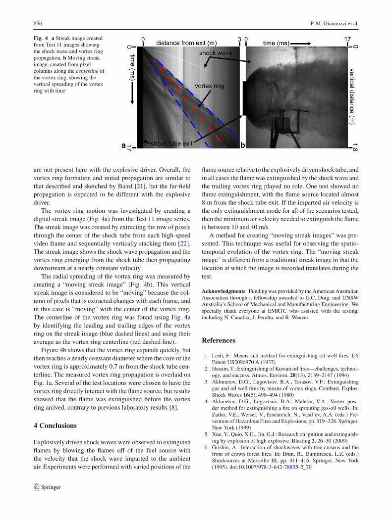
Fig. 4 a Streak image createdfrom Test 11 images showingthe shock wave and vortex ringpropagation. bMoving streakimage, created from pixelcolumns along the centerline ofthe vortex ring, showing thevertical spreading of the vortexring with time
are not present here with the explosive driver. Overall, thevortex ring formation and initial propagation are similar tothat described and sketched by Baird [21], but the far-fieldpropagation is expected to be different with the explosivedriver.
The vortex ring motion was investigated by creating adigital streak image (Fig. 4a) from the Test 11 image series.The streak image was created by extracting the row of pixelsthrough the center of the shock tube from each high-speedvideo frame and sequentially vertically stacking them [22].The streak image shows the shock wave propagation and thevortex ring emerging from the shock tube then propagatingdownstream at a nearly constant velocity.
The radial spreading of the vortex ring was measured bycreating a “moving streak image” (Fig. 4b). This verticalstreak image is considered to be “moving” because the col-umn of pixels that is extracted changes with each frame, andin this case is “moving” with the center of the vortex ring.The centerline of the vortex ring was found using Fig. 4aby identifying the leading and trailing edges of the vortexring on the streak image (blue dashed lines) and using theiraverage as the vortex ring centerline (red dashed line).
Figure 4b shows that the vortex ring expands quickly, butthen reaches a nearly constant diameter where the core of thevortex ring is approximately 0.7 m from the shock tube cen-terline. The measured vortex ring propagation is overlaid onFig. 1a. Several of the test locations were chosen to have thevortex ring directly interact with the flame source, but resultsshowed that the flame was extinguished before the vortexring arrived, contrary to previous laboratory results [8].
4 Conclusions
Explosively driven shock waves were observed to extinguishflames by blowing the flames off of the fuel source withthe velocity that the shock wave imparted to the ambientair. Experiments were performed with varied positions of the
flame source relative to the explosively driven shock tube, andin all cases the flamewas extinguished by the shockwave andthe trailing vortex ring played no role. One test showed noflame extinguishment, with the flame source located almost8 m from the shock tube exit. If the imparted air velocity isthe only extinguishment mode for all of the scenarios tested,then theminimum air velocity needed to extinguish the flameis between 10 and 40 m/s.
A method for creating “moving streak images” was pre-sented. This technique was useful for observing the spatio-temporal evolution of the vortex ring. The “moving streakimage” is different from a traditional streak image in that thelocation at which the image is recorded translates during thetest.
Acknowledgments Fundingwas provided by theAmericanAustralianAssociation through a fellowship awarded to G.C. Doig, and UNSWAustralia’s School of Mechanical and Manufacturing Engineering. Wespecially thank everyone at EMRTC who assisted with the testing,including N. Canafax, J. Peralta, and R. Weaver.
References
1. Lesh, F.: Means and method for extinguishing oil well fires. USPatent US2096970 A (1937)
2. Husain, T.: Extinguishing of Kuwait oil fires—challenges, technol-ogy, and success. Atmos. Environ. 28(13), 2139–2147 (1994)
3. Akhmetov, D.G., Lugovtsov, B.A., Tarasov, V.F.: Extinguishinggas and oil well fires by means of vortex rings. Combust. Explos.Shock Waves 16(5), 490–494 (1980)
4. Akhmetov, D.G., Lugovtsov, B.A., Maletin, V.A.: Vortex pow-der method for extinguishing a fire on sprouting gas-oil wells. In:Zarko, V.E., Weiser, V., Eisenreich, N., Vasil’ev, A.A. (eds.) Pre-vention of Hazardous Fires and Explosions, pp. 319–328. Springer,New York (1999)
5. Xue, Y., Quio, X.H., Jin, G.J.: Research on ignition and extinguish-ing by explosion of high explosive. Blasting 2, 26–30 (2009)
6. Grishin, A.: Interaction of shockwaves with tree crowns and thefront of crown forest fires. In: Brun, R., Dumitrescu, L.Z. (eds.)Shockwaves at Marseille III, pp. 411–416. Springer, New York(1995). doi:10.1007/978-3-642-78835-2_70
123
Explosive-driven shock wave and vortex ring interaction with a propane flame 857
7. Doig, G.C., Johnson, Z., Mann, R.: Shock wave interaction with aflame. In: 18th Australasian Fluid Mechanics Conference (2012)
8. Doig, G.C., Johnson, Z., Mann, R.: Interaction of a shock tubeexhaust flowwith a non-premixed flame. J. Vis. 16, 173–176 (2013)
9. Kilchyk, V., Nalim, R., Merkle, C.: Laminar premixed flame fuelconsumption rate modulation by shocks and expansion waves.Combust. Flame 158(6), 1140–1148 (2011)
10. Kilchyk, V., Nalim, R., Merkle, C.: Scaling interface lengthincrease rates in Richtmyer-Meshkov instabilities. J. Fluids Eng.135(3), 031,203 (2013)
11. Akhmetov, D.G.: Formation and basic parameters of vortex rings.J. Appl. Mech. Techn. Phys. 42(5), 794–805 (2001)
12. Kashimura, H., Yasunobu, T., Nakayama, H., Setoguchi, T., Mat-suo, K.: Discharge of a shock wave from an open end of a tube. J.Therm. Sci. 9(1), 30–36 (2000)
13. Murugan, T., Sudipta, S., Laxmana, D., Das, D.: Numerical simu-lation and PIV study of formation and evolution of compressiblevortex ring. Shock Waves 22(1), 69–83 (2012)
14. Murugan, T., Das, D.: Characteristics of counter-rotating vortexrings formed ahead of a compressible vortex ring. Exp. Fluids 49,1247–1261 (2010)
15. Dabiri, J.O., Gharib,M.: Fluid entrainment by isolated vortex rings.J. Fluid Mech. 511, 311–331 (2004)
16. Chan, J.E., Giannuzzi, P., Kabir, K.R., Hargather, M.J., Doig, G.:Interactions of shock tube exhaust flows with laminar and turbulentflames In: AIAASciTech. SanDiego, CA, Paper AIAA-2016-1588(2016)
17. Hargather, M.J., Settles, G.S.: Retroreflective shadowgraph tech-nique for large-scale visualization. Appl. Optics 48, 4449–4457(2009)
18. Settles, G.S.: Schlieren and shadowgraph techniques: Visualiz-ing phenomena in transparent media. Springer-Verlag, Heidelberg(2001)
19. Hargather, M.J., Settles, G.S.: Optical measurement and scaling ofblasts from gram-range explosive charges. Shock Waves 17, 215–223 (2007)
20. Dewey, J.M.: Explosive flows: Shock tubes and blast waves. In:Handbook of Flow Visualization, 1st edn., book chapter 29, pp.481–497. Hemisphere Publishing Corp. (1989)
21. Baird, J.P.: Supersonic vortex rings. Proceedings of the Royal Soci-ety of London. Series A, Mathematical and Physical Sciences409(1836), 59–65 (1987)
22. Kleine, H.: Time-resolved visualization of transient compressibleflows. In: 15th International Symposium on Flow Visualization,Minsk, Belarus, Paper ISFV15-158 (2012)
123