Embed Size (px)
Citation preview
Exploring TeleRobotics:A Radio-Controlled Robot
Waiter F. Deal, IU and Steve C. Hsiung
This article introduces the concept
of teierobotics—that is to controi a
robotic system remoteiy using iow-
cost, off-the-sheif radio transmitter
and receiver electronics.
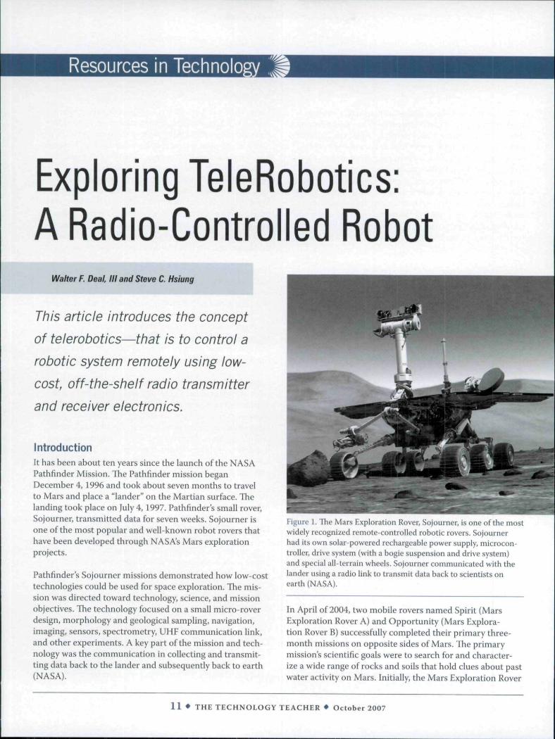
IntroductionIt has been about ten years since the launch of the NASAPathfinder Mission. The Pathfinder mission beganDecember 4, 1996 and took about seven months to travelto Mars and place a "lander" on the Martian surface. Thelanding took place on July 4, 1997. Pathfinder's small rover,Sojourner, transmitted data for seven weeks. Sojourner isone of the most popular and well-known robot rovers thathave been developed through NASA's Mars explorationprojects.
Pathfinder's Sojourner missions demonstrated how low-costtechnologies could be used for space exploration. The mis-sion was directed toward technology, science, and missionobjectives. The technology focused on a small micro-roverdesign, morphology and geological sampling, navigation,imaging, sensors, spectrometry, UHF communication link,and other experiments. A key part ofthe mission and tech-nology was the communication in collecting and transmit-ting data back to the lander and subsequently back to earth(NASA).
Figure 1. The Mars Exploration Rover, Sojourner, is one ofthe mostwidely recognized remote-controlled robotic rovers. Sojournerhad its own solar-powered rechargeable power supply, microcon-troller, drive system (with a bogie suspension and drive system)and special all-terrain wheels. Sojourner communicated with thelander using a radio link to transmit data back to scientists onearth (NASA).
In April of 2004, two mobile rovers named Spirit (MarsExploration Rover A) and Opportunity (Mars Explora-tion Rover B) successfully completed their primary three-month missions on opposite sides of Mars. The primarymission's scientific goals were to search for and character-ize a wide range of rocks and soils that hold clues about pastwater activity on Mars. Initially, the Mars Exploration Rover
1 1 • THE TECHNOLOGY TEACHER • October 2007
mission was to last about 90 days and, as of this writingthree years later. Spirit and Opportunity are still collectingdata and transmitting it back to earth. Unlike the Sojournerrover, Spirit and Opportunity have enhanced communica-tions systems that enable them to communicate with earthstations directly and with spacecraft orbiting Mars. How-ever, Spirit and Opportunity communicated with the orbiterOdyssey to transmit scientific and image data back to earthstations as opposed to a relay link from the rovers to thelander. (MER). As a result ofthe media coverage ofthe Marsmissions ofthe Sojourner, Spirit, and Opportunity rovers,there has been a significant increase in interest in roboticsand control technology.
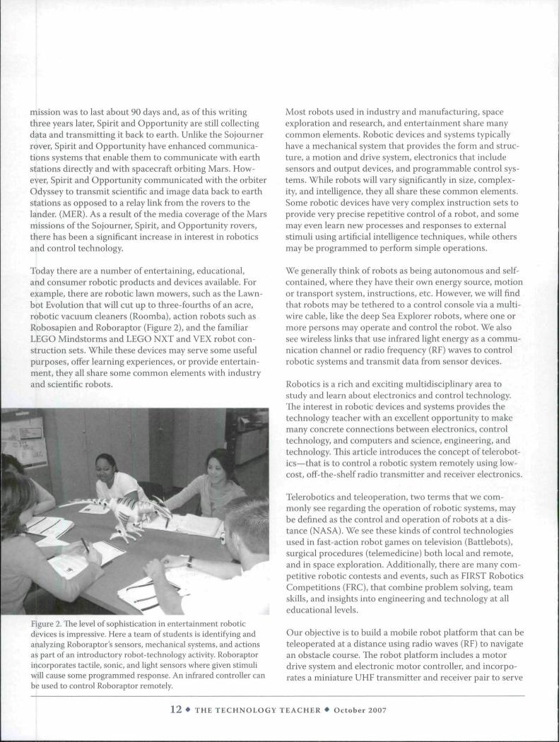
Today there are a number of entertaining, educational,and consumer robotic products and devices available. Forexample, there are robotic lawn mowers, such as the Lawn-bot Evolution that will cut up to three-fourths of an acre,robotic vacuum cleaners (Roomba), action robots such asRobosapien and Roboraptor (Figure 2), and the familiarLEGO Mindstorms and LEGO NXT and VEX robot con-struction sets. While these devices may serve some usefulpurposes, offer learning experiences, or provide entertain-ment, they all share some common elements with industryand scientific robots.
Figure 2. The level of sophistication in entertainment roboticdevices is impressive. Here a team of students is identifying andanalyzing Roboraptor's sensors, mechanical systems, and actionsas part of an introductory robot-technology activity. Roboraptorincorporates tactile, sonic, and light sensors where given stimuliwill cause some programmed response. An infrared controller canbe used to control Roboraptor remotely.
Most robots used in industry and manufacturing, spaceexploration and research, and entertainment share manycommon elements. Robotic devices and systems typicallyhave a mechanical system that provides the form and struc-ture, a motion and drive system, electronics that includesensors and output devices, and programmable control sys-tems. While robots will vary significantly in size, complex-ity, and intelligence, they all share these common elements.Some robotic devices have very complex instruction sets toprovide very precise repetitive control of a robot, and somemay even learn new processes and responses to externalstimuli using artificial intelligence techniques, while othersmay be programmed to perform simple operations.
We generally think of robots as being autonomous and self-contained, where they have their own energy source, motionor transport system, instructions, etc. However, we will findthat robots may be tethered to a control console via a multi-wire cable, like the deep Sea Explorer robots, where one ormore persons may operate and control the robot. We alsosee wireless links that use infrared light energy as a commu-nication channel or radio frequency (RF) waves to controlrobotic systems and transmit data from sensor devices.
Robotics is a rich and exciting multidisciplinary area tostudy and learn about electronics and control technology.The interest in robotic devices and systems provides thetechnology teacher with an excellent opportunity to makemany concrete connections between electronics, controltechnology, and computers and science, engineering, andtechnology. Tliis article introduces the concept of teierobot-ics—that is to control a robotic system remotely using low-cost, off-the-shelf radio transmitter and receiver electronics.
Teierobotics and teleoperation, two terms that we com-monly see regarding the operation of robotic systems, maybe defined as the control and operation of robots at a dis-tance (NASA). We see these kinds of control technologiesused in fast-action robot games on television (Battlebots),surgical procedures (telemedicine) both local and remote,and in space exploration. Additionally, there are many com-petitive robotic contests and events, such as FIRST RoboticsCompetitions (FRC), that combine problem solving, teamskills, and insights into engineering and technology at alleducational levels.
Our objective is to build a mobile robot platform that can beteleoperated at a distance using radio waves (RF) to navigatean obstacle course. The robot platform includes a motordrive system and electronic motor controller, and incorpo-rates a miniature UHF transmitter and receiver pair to serve
1 2 • THE TECHNOLOGY TEACHER • October 2007
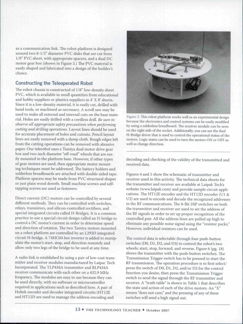
as a communication link. The robot platform is designedaround two 8-1/2" diameter PVC disks that are cut from1/8" PVC sheet, with appropriate spacers, and a dual DCmotor gear box (shown in Figure 3,) The PVC material iseasily shaped and fabricated into a design ofthe builder'schoice.
Constructing the Teleoperated RobotThe robot chassis is constructed of 1/8" low-density sheetPVC, which is available in small quantities from educationaland hobby suppliers or plastics suppliers in 4' X 8' sheets.Since it is a low-density material. It is easily cut, drilled withhand tools, or machined as necessary. A scroll saw may beused to make all external and internal cuts on the base mate-rial. Holes are easily drilled with a cordless drill. Be sure toobserve all appropriate safety precautions when performingcutting and drilling operations. Layout lines should be usedfor accurate placement of holes and cutouts. Pencil layoutlines are easily removed with a damp cloth. Rough edges leftfrom the cutting operations can be removed with abrasivepaper. Our telerobot uses a Tamiya dual motor drive gearbox and two-inch diameter "off-road" wheels that are eas-ily mounted to the platform base. However, if other typesof gear motors are used, then appropriate motor mount-ing techniques must be addressed. The battery holders andsolderless breadboards are attached with double-sided tape.Platform spacers may be made from PVC structural shapesor just plain wood dowels. Small machine screws and self-tapping screws are used as fasteners.
Direct current (DC) motors can be controlled by severaldifferent methods. They can be controlled with switches,relays, transistors, and silicon-controlled rectifiers, andspecial integrated circuits called H-Bridges. It is a commonpractice to use a special circuit design called an H-bridge tocontrol a DC motor's current in order to determine speedand direction of rotation. The two Tamiya motors mountedon a robot platform are controlled by an L293D integratedcircuit H-bridge. A 74HC04 hex inverter is added to manip-ulate the motor's start, stop, and direction remotely andallow only two legs of the bridge to be used at any time.
A radio link is established by using a pair of low-cost trans-mitter and receiver modules manufactured by Laipac Techincorporated. The TLP434A transmitter and RLP434Areceiver communicate with each other on a 432.9 MHzfrequency. The modules are easy to use because they canbe used directly, with no software or microcontrollerrequired in applications such as described here. A pair ofHoltek encoder and decoder integrated circuits (HT12Eand HT12D are used to manage the address encoding and
Figure 3. This robot platform works well as an experimental designbecause the electronics and control systems can be easily modifiedby using a solderless breadboard. The receiver module can be seenon the right side of the socket. Additionally, you can see the dualH-Bridge driver that is used to control the operational status ofthemotors. Logic states can be used to turn the motors ON or OFF aswell as change direction.
decoding and checking of the validity of the transmitted andreceived data.
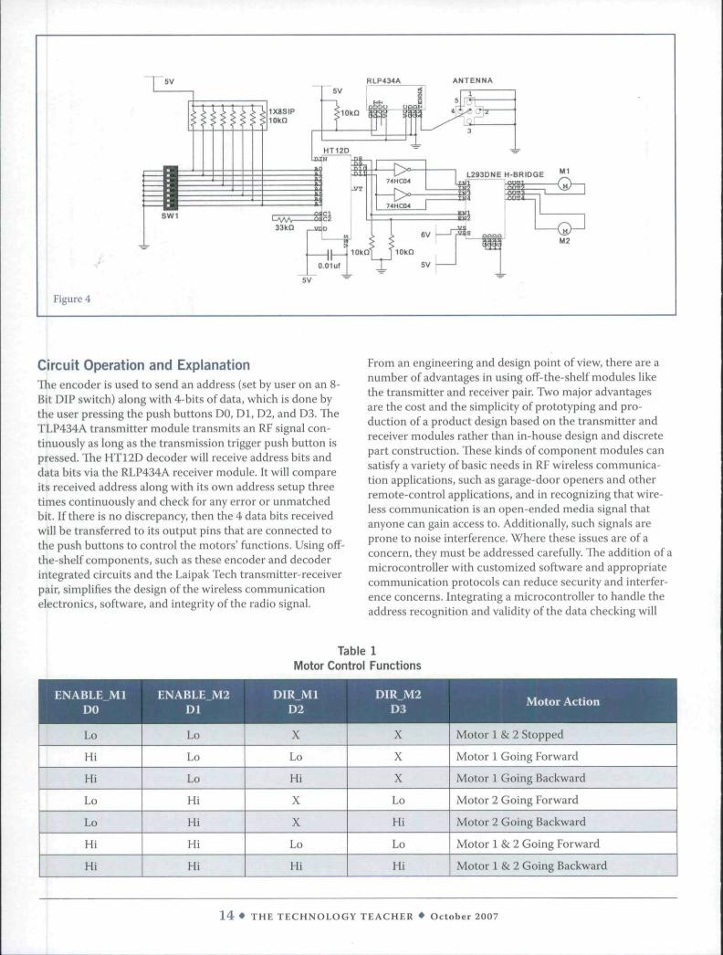
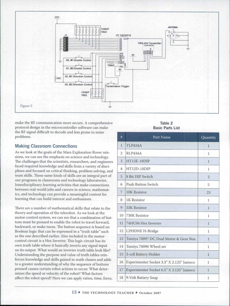
Figures 4 and 5 show the schematic of transmitter andreceiver used in this activity. The technical data sheets forthe transmitter and receiver are available at Laipak Tech'swebsite (www.laipak.com) and provide sample circuit appli-cations. The HT12E encoder and the HT12D encoder (Ul &U2) are used to encode and decode the recognized addressesin the RF communications. The 8-Bit DIP switches on boththe transmitter and receiver are used to set the address ofthe RF signals in order to set up proper recognition ofthecontrolled pair. All the address lines are pulled up high toeliminate any possible noise signal using the "resistor packs."However, individual resistors can be used.
The control data is selectable through four push-buttonswitches (DO, Dl, D2, and D3) to control the robot's twowheels: start, stop, forward, and reverse. Figure 6 (pg. 18)shows the transmitter with the push-button switches. TheTransmission Trigger switch has to be pressed to start theRF transmission. The operation procedure is to first select/press the switch of DO, Dl, D2, and/or D3 for the controlfunction you desire, then press the Transmission Triggerswitch to send the signal through the RF transmitter andreceiver. A "truth table" is shown in Table 1 that describesthe state and action of each ofthe drive motors. An "X"means "does not care," and the pressing of any of theseswitches will send a high signal out.
1 3 • THE TECHNOLOGY TEACHER • October 2007
BLP434A ANTENNA
M2
Figure 4
Circuit Operation and ExplanationThe encoder is used to send an address (set by user on an 8-Bit DIP switch) along with 4-bits of data, which is done bythe user pressing the push buttons DO, Dl, D2, and D3. TheTLP434A transmitter module transmits an RF signal con-tinuously as long as the transmission trigger push button ispressed. The HT12D decoder will receive address bits anddata bits via the RLP434A receiver module. It will compareits received address along with its own address setup threetimes continuously and check for any error or unmatchedbit. If there is no discrepancy, then the 4 data bits receivedwill be transferred to its output pins that are connected tothe push buttons to control the motors' functions. Using off-the-shelf components, such as these encoder and decoderintegrated circuits and the Laipak Tech transmitter-receiverpair, simplifies the design ofthe wireless communicationelectronics, software, and integrity ofthe radio signal.
From an engineering and design point of view, there are anumber of advantages in using off-the-shelf modules likethe transmitter and receiver pair. Two major advantagesare the cost and the simplicity of prototyping and pro-duction of a product design based on the transmitter andreceiver modules rather than in-house design and discretepart construction. These kinds of component modules cansatisfy a variety of basic needs in RF wireless communica-tion applications, such as garage-door openers and otherremote-control applications, and in recognizing that wire-less communication is an open-ended media signal thatanyone can gain access to. Additionally, such signals areprone to noise interference. Where these issues are of aconcern, they must be addressed carefully. The addition of amicrocontroller with customized software and appropriatecommunication protocols can reduce security and interfer-ence concerns. Integrating a microcontroller to handle theaddress recognition and validity ofthe data checking will
Table 1Motor Control Functions
ENABLE_M1DO
Lo
Hi
Hi
Lo
Lo
Hi
Hi
ENABLE M ^Dl 9Lo
1.0
Lo
Hi
Hi
Hi
Hi
DIR Ml ^ ^
• I"' 11X
Lo
Hi
X
X
Lo
Hi
X
X
X
Lo
Hi
Lo
Hi
^ H ^ Motor Action
Motor 1 & 2 Stopped
Motor 1 Going Forward
Motor 1 Going Backward
Motor 2 Going Forward
Motor 2 Going Backward
Motor 1 & 2 Going Forward
Motor 1 & 2 Going Backward
1 4 • THE TECHNOLOGY TEACHER • October 2007
vcc
Figure 5
make the RF communication more secure. A comprehensiveprotocol design in the microcontroller software can makethe RF signal difficult to decode and less prone to noiseproblems.
Making Classroom ConnectionsAs we look at the goals ofthe Mars Exploration Rover mis-sions, we can see the emphasis on science and technology.The challenges that the scientists, researchers, and engineersfaced required knowledge and skills from a variety of disci-plines and focused on critical thinking, problem solving, andteam skills. These same kinds of skills are an integral part ofour programs in classrooms and technology laboratories.Interdisciplinary learning activities that make connectionsbetween real-world jobs and careers in science, mathemat-ics, and technology can provide a meaningful context forlearning that can build interest and enthusiasm.
There are a number of mathematical skills that relate to thetheory and operation ofthe telerobot. As we look at tbemotor-control system, we can see tbat a combination of but-tons must be pressed to enable the robot to travel forward,backward, or make turns. The button sequence is based onBoolean logic that can be expressed in a "truth table" suchas the one described earlier. Also included in the motor-control circuit is a Hex Inverter. This logic circuit has itsown truth table where it basically inverts any signal inputon its output. What would an inverter truth table look like?Understanding the purpose and value of truth tables rein-forces knowledge and skills gained in math classes and addsto a greater understanding of why the sequence of buttonspressed causes certain robot actions to occur. What deter-mines the speed or velocity of the robot? What factorsaffect the robot speed? Here we can apply ratios, time, force,
Table 2Basic Parts List
Part Name Quantity
1
2
3
4
5
6
7
8
9
10
11
12
13
14
15
16
17
18
TLP434A
RLP434A
HT12E-18DIP
HT12D-18DIP
8 Bit DIP Switch
Push Button Switch
lOK Resistor
IK Resistor
33K Resistor
730K Resistor
74HC04 Hex Inverter
L293DNE H-Bridge
Tamiya 70097 DC Dual Motor & Gear Box
Tamiya 70096 Wheel set
3-cell Battery Holder
Experimenter Socket 3.3" X 2.125" |ameco
Experimenter Socket 6.5" X 2.125" Jameco
9-Volt Battery Snap
1
1
1
1
2
5
23
1
1
1
1
1
1
1
1
1
1
1
15 • THE TECHNOLOGY TEACHER • October 2007
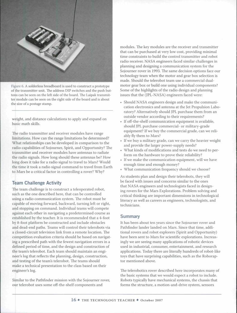
Figure 6. A solderless breadboard is used to construct a prototypeof tbe transmitter unit. The address DIP switches and the push but-tons can be seen on the left side of tbe board. The Laipak transmit-ter moduie can be seen on the right side ofthe board and is aboutthe size of a postage stamp.
weight, and distance calculations to apply and expand onbasic math skills.
The radio transmitter and receiver modules have rangelimitations. How can the range limitations be determined?What relationships can be developed in comparison to theradio capabilities of Sojourner, Spirit, and Opportunity? Thetransmitter and receiver modules have antennas to radiatethe radio signals. How long should these antennas be? Howlong does it take for a radio signal to travel to Mars? Wouldthe time it took a radio signal command to travel from Earthto Mars be a critical factor in controlling a rover? Why?
Team Challenge ActivityThe team challenge is to construct a teleoperated robot,such as the one described here, that can be controlledusing a radio communication system. The robot must becapable of moving forward, backward, turning left or right,and stopping on command. Individual teams will competeagainst each other in navigating a predetermined course asestablished by the teacher. It is recommended that a 4-footby 8 foot platform be constructed and include obstaclesand dead-end paths. Teams will control their telerobots viaa closed-circuit television link from a remote location. Tliecompetition evaluation criteria should be based on navigat-ing a prescribed path with the fewest navigation errors in adefined period of time, and the design and construction ofthe team's telerobot. Each team should maintain an engi-neer's log that reflects the planning, design, construction,and testing ofthe team's telerobot. The teams shouldmake a technical presentation to the class based on theirengineer's log.
Similar to the Pathfinder mission with the Sojourner rover,our telerobot uses some off-the-shelf components and
modules. The key modules are the receiver and transmitterthat can be purchased at very low cost, providing minimaltime constraints to build the control transmitter and robotradio receiver. NASA engineers faced similar challenges inplanning and designing a communication system for theSojourner rover in 1993. The same decision options face ourtechnology team when the motor and gear box selection ismade. Should the telerobot team use a commercial dual-motor gear box or build one using individual components?Some ofthe highlights ofthe radio design and planningissues that the (JPL-NASA) engineers faced were:
• Should NASA engineers design and make the communi-cation electronics and antenna at the Jet Propulsion Labo-ratory? Alternatively should IPE purchase them from anoutside vendor according to their requirements?
• If off-the-shelf communication equipment is available,should JPL purchase commercial- or military-gradeequipment? If we buy the commercial grade, can we reli-ably fly them to Mars?
• If we buy a military grade, can we carry the heavier weightand provide the larger power-supply needs?
• What kinds of modifications and tests do we need to per-form on the hardware to prove their reliability?
• If we make the communication equipment, will we haveenough time and enough money?
• What communication frequency should we choose?
As students plan and design their telerobots, they willbe faced with issues and concerns similar to the onesthat NASA engineers and technologists faced in design-ing rovers for the Mars Explorations. Problem solving andcritical thinking are important dimensions in technologicalliteracy as weli as careers as engineers, technologists, andtechnicians.
SummaryIt has been about ten years since the Sojourner rover andPathfinder lander landed on Mars. Since that time, addi-tional rovers and robot explorers (Spirit and Opportunity)have been sent to Mars for scientific explorations. Increas-ingly we are seeing many applications of robotic devicesused in industrial, consumer, entertainment, and researchapplications. Today there are literally hundreds of robot-liketoys that have surprising capabilities, such as the Roborap-tor mentioned above.
The teierobotics rover described here incorporates many ofthe basic systems that we would expect a robot to include.Robots typically have mechanical systems, the chassis thatforms the structure, a motion-and-drive system, sensors
1 6 • THE TECHNOLOGY TEACHER • October 2007
and output devices such as a manipula-tor or arm, and a control system that maybe programmable or remotely operated. Inaddition to these basic systems, teleroboticdevices have some means to enable remoteoperation either by a tethered cable orradio-frequency technologies.
The telerobot uses off-the-shelf compo-nents as part of a radio-controlled robotsystem. The radio transmitter and receiverpair uses encoder and decoder integratedcircuits to manage an addressing-and-control scheme that allows the user tosimply press control buttons to remotelycontrol driver motors that can be used tonavigate the robot.
There are opportunities for problem solv-ing, critical thinking, and the application oflogic and math in the design and construc-tion ofthe telerobot. ^
ResourcesNASA Sojourner. Retrieved June 15, 2007.
http://mpfwww.jpl.nasa.gov/MPF/mpf-pressrel.html.
Mars Exploration Rovers (MER). RetrievedJuly 15, 2007. http://en.wikipedia.org/wiki/Mars_Exploration Rover.
NASA Teierobotics. Retrieved July 10,2007. http://quest.arc.nasa.gov/space/teachers/liftoff/robotics.html.
JPL-NASA Sojourner Communication.Retrieved July 10, 2007. http://mars.jpl.nasa.gov/MPF/rovercom/radio.html.
Walter F. Deal, III, Ph.D.is an associate profes-sor and Program Leaderof Technology Educationand Industrial TechnologyPrograms at Old Domin-ion University in Norfolk,
VA. He can be reached via email at [email protected].
Steve C. Hsiung, Ph.D.(5 an associate professorof Engineering Technologyat Old Dominion Univer-sity, Norfolk, VA. He canbe reached via email [email protected].
VIDEOPRODUCnON
New Standards®Video Labs
Video Labs with DVD & DVbased camcorders orstand-alone systems,
OPTIONAL: 1 or 2 camcorders.
KELVIN" also has a variety ofmodular labs for Technology,
Science and Electronics,
Promoting Engineering & Design in Our Sciioois
Creative Crane
Available inTeam Class Packsin Wood or Balsa.
From start to finish, the challenge is to use creativeproblem-solving and design skills. Students designand build a lightweight crane that creatively lifts avariable load aminimum verticalheight with aminimum horizontalclearance distance.
Also Check OutThe KELVINBalsaStiKutter
Students Design a VehicieThat Ciimbs Over
Obstacles!TM
MONSTER VEHICLES DESIGN CHALLENGECompete in the newest engineering challenge! Yourstudents design the truck from a basic kit availablefrom KELVIN", then work in teams or individually todesign and construct springs and propulsion system.
LABS - CURRICULUM • FURNITURE • SOFTWARE • K-12 • SCIENCE • STRUCTURES • PARTSELECTRONICS • TRANSPORTATION • COMMUNICATIONS • ROBOTICS * BOOKS • TOOLSCOMPUTERS • ENERGY & POWER • MANUFACTURING • OESIGN • MODELING • VIDEOS
1 7 • THE TECHNOLOGY TEACHER • October 2007