Embed Size (px)
Citation preview

Explanatory Note to TCDS IM.A.120 – Boeing 737 - Issue 04
Disclaimer – This document is not exhaustive and it will be updated gradually. Page 1 of 16
This annex to the EASA TCDS IM.A.120 was created to publish selected special conditions /
deviations / equivalent safety findings that are part of the applicable certification basis:
Table of Contents:
Certification Review Items:
A-10: Additional requirements for import ...........................................................................................2 C-01: Pressurised Cabin Loads ............................................................................................................4 D-14: Exit configuration ......................................................................................................................5 D-GEN 2 PTC: Application of heat release and smoke density requirements to seat materials ........6
E-10: Flammability Reduction System ...............................................................................................7 F-01: High Intensity Radiated Fields .................................................................................................12 F-02: Protection from the effects of Lightning strike; direct effects ..................................................13 F-03: Protection from the effects of Lightning Srike; indirect effects ...............................................14 H-01: Enhanced airworthiness programme for aeroplane systems – ICA on EWIS .......................15
Explanatory Note to TCDS IM.A.120 – Boeing 737 - Issue 04
Disclaimer – This document is not exhaustive and it will be updated gradually. Page 2 of 16
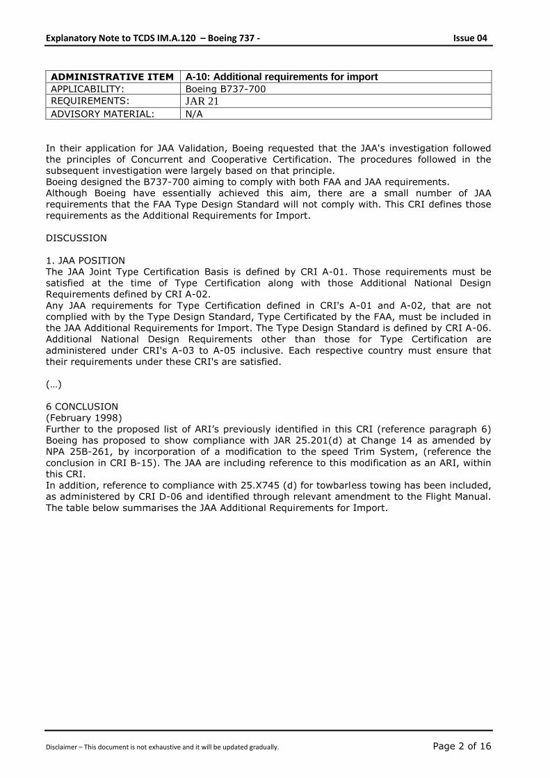
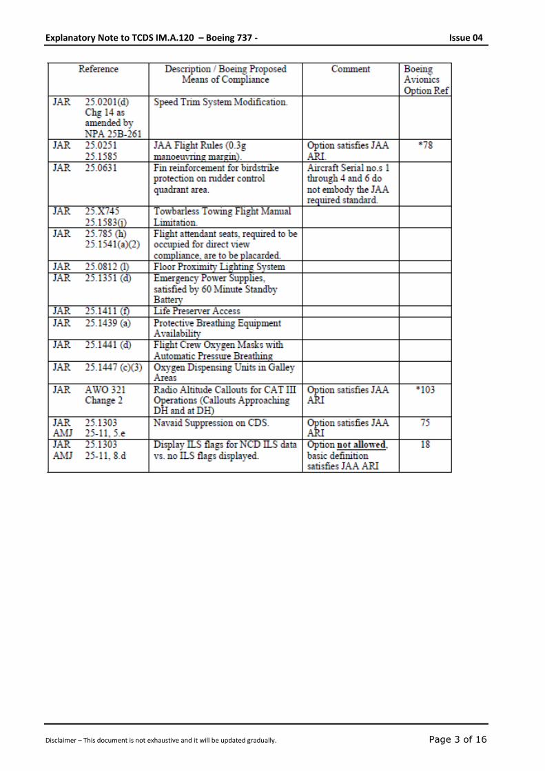
ADMINISTRATIVE ITEM A-10: Additional requirements for import
APPLICABILITY: Boeing B737-700
REQUIREMENTS: JAR 21 ADVISORY MATERIAL: N/A
In their application for JAA Validation, Boeing requested that the JAA's investigation followed
the principles of Concurrent and Cooperative Certification. The procedures followed in the
subsequent investigation were largely based on that principle.
Boeing designed the B737-700 aiming to comply with both FAA and JAA requirements.
Although Boeing have essentially achieved this aim, there are a small number of JAA
requirements that the FAA Type Design Standard will not comply with. This CRI defines those
requirements as the Additional Requirements for Import.
DISCUSSION
1. JAA POSITION
The JAA Joint Type Certification Basis is defined by CRI A-01. Those requirements must be
satisfied at the time of Type Certification along with those Additional National Design
Requirements defined by CRI A-02.
Any JAA requirements for Type Certification defined in CRI's A-01 and A-02, that are not
complied with by the Type Design Standard, Type Certificated by the FAA, must be included in
the JAA Additional Requirements for Import. The Type Design Standard is defined by CRI A-06.
Additional National Design Requirements other than those for Type Certification are
administered under CRI's A-03 to A-05 inclusive. Each respective country must ensure that
their requirements under these CRI's are satisfied.
(…)
6 CONCLUSION
(February 1998)
Further to the proposed list of ARI’s previously identified in this CRI (reference paragraph 6)
Boeing has proposed to show compliance with JAR 25.201(d) at Change 14 as amended by
NPA 25B-261, by incorporation of a modification to the speed Trim System, (reference the
conclusion in CRI B-15). The JAA are including reference to this modification as an ARI, within
this CRI.
In addition, reference to compliance with 25.X745 (d) for towbarless towing has been included,
as administered by CRI D-06 and identified through relevant amendment to the Flight Manual.
The table below summarises the JAA Additional Requirements for Import.
Explanatory Note to TCDS IM.A.120 – Boeing 737 - Issue 04
Disclaimer – This document is not exhaustive and it will be updated gradually. Page 3 of 16

Explanatory Note to TCDS IM.A.120 – Boeing 737 - Issue 04
Disclaimer – This document is not exhaustive and it will be updated gradually. Page 4 of 16
SPECIAL CONDITION C-01: Pressurised Cabin Loads
APPLICABILITY: Boeing B737-600/-700/-800/-900
REQUIREMENTS: JAR 25.365 and JAA INT/POL/25/7 ADVISORY MATERIAL: N/A
In addition to the specific requirement of JAR 25.365(e), all structure, components or parts,
both internal and external to the pressurised compartments, the failure of which could
interfere with continued safe flight and landing, must be designed to withstand the differential
pressure loads resulting from a sudden release of pressure through the openings specified in
JAR 25.365(e) at any approved operating altitude.
In complying with this requirement, the differential pressure must be combined in a rational
and conservative manner with the 1-g level flight loads and any loads arising from the
emergency depressurisation conditions. These may be considered as ultimate conditions;
however any deformations associated with these conditions must not interfere with continued
safe flight and landing.
Explanatory Note to TCDS IM.A.120 – Boeing 737 - Issue 04
Disclaimer – This document is not exhaustive and it will be updated gradually. Page 5 of 16
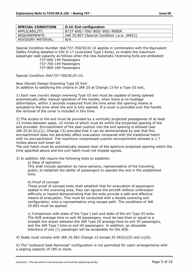
SPECIAL CONDITION D-14: Exit configuration
APPLICABILITY: B737-600/-700/-800/-900/-900ER
REQUIREMENTS: JAR 25.807 (Special Condition i.a.w. JAR21) ADVISORY MATERIAL: N/A
Special Condition Number JAA/737-700/SC/D-14 applies in combination with the Equivalent
Safety Finding detailed in CRI D-17 (oversized Type I Exits), to enable the maximum
passenger seat capacity as follows when the new Automatic Overwing Exits are embodied:
737-600 149 Passengers
737-700 149 Passengers
737-800 189 Passengers
Special Condition JAA/737-700/SC/D-14;
New (Novel) Design Overwing Type III Exit:
In addition to satisfying the criteria in JAR 25 at Change 13 for a Type III exit;
1) Each new (novel) design overwing Type III exit must be capable of being opened
automatically after manual operation of the handle, when there is no fuselage
deformation, within 3 seconds measured from the time when the opening means is
actuated to the time when the exit is fully opened. If a cover is provided over the handle
the removal of the cover is included in this time.
2) The access to the exit must be provided by a vertically projected passageway of at least
13 inches between seats, 10 inches of which must be within the projected opening of the
exit provided. Encroachment of the seat cushion into the exit opening is allowed (see
JAR 25.813(c)(1), Change 13) provided that it can be demonstrated by test that this
encroachment does not adversely affect evacuation compared with the traditional hatch
with no encroachment. The maximum compressed cushion encroachment allowed is 1.7
inches above exit lower sill.
The exit hatch must be automatically stowed clear of the aperture projected opening within the
time specified above and the exit hatch must not impede egress.
3) In addition JAA require the following tests to establish:
a) Ease of operation
This shall include operation by naive persons, representative of the travelling
public, to establish the ability of passengers to operate the exit in the established
time.
b) Proof of concept
These proof of concept tests shall establish that for evacuation of passengers
seated in the overwing area, they can egress the aircraft without unforeseen
difficulty or hazard demonstrating that the exits provide a safe and effective
means of evacuation. This must be conducted with a double overwing exit
configuration, onto a representative wing escape path. The conditions of JAR
25.803 must be applied.
c) Comparison with state of the Type I exit and state of the art Type III exits.
The AOE average time to exit 40 passengers, must be less than or equal to a
straight line drawn between the JAR Type III average time to exit 35 passengers,
and the JAR Type I time to exit 45 passengers. In addition, an allowable
tolerance of one (1) passenger will be acceptable for the AOE.
4) Seats must comply with JAR 25.562 Change 13 except 25.562(c)(5) and (c)(6).
5) The “outboard Seat Removed” configuration is not permitted for cabin arrangements with
a seating capacity of 185 or more.
Explanatory Note to TCDS IM.A.120 – Boeing 737 - Issue 04
Disclaimer – This document is not exhaustive and it will be updated gradually. Page 6 of 16
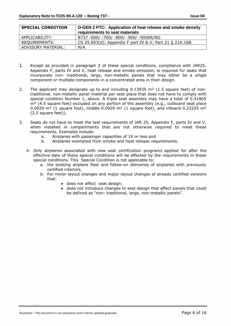
SPECIAL CONDITION D-GEN 2 PTC: Application of heat release and smoke density requirements to seat materials
APPLICABILITY: B737 -600/ -700/ -800/ -900/ -900ER/NG
REQUIREMENTS: CS 25.853(d); Appendix F part IV & V; Part 21 § 21A.16B ADVISORY MATERIAL: N/A
1. Except as provided in paragraph 3 of these special conditions, compliance with JAR25,
Appendix F, parts IV and V, heat release and smoke emission, is required for seats that
incorporate non- traditional, large, non-metallic panels that may either be a single
component or multiple components in a concentrated area in their design.
2. The applicant may designate up to and including 0.13935 m² (1.5 square feet) of non-
traditional, non-metallic panel material per seat place that does not have to comply with
special condition Number 1, above. A triple seat assembly may have a total of 0.41805
m² (4.5 square feet) excluded on any portion of the assembly (e.g., outboard seat place
0.0929 m² (1 square foot), middle 0.0929 m² (1 square foot), and inboard 0.23225 m²
(2.5 square feet)).
3. Seats do not have to meet the test requirements of JAR 25, Appendix F, parts IV and V,
when installed in compartments that are not otherwise required to meet these
requirements. Examples include:
a. Airplanes with passenger capacities of 19 or less and
b. Airplanes exempted from smoke and heat release requirements.
4. Only airplanes associated with new seat certification programs applied for after the
effective date of these special conditions will be affected by the requirements in these
special conditions. This Special Condition is not applicable to:
a. the existing airplane fleet and follow-on deliveries of airplanes with previously
certified interiors,
b. For minor layout changes and major layout changes of already certified versions
that:
does not affect seat design;
does not introduce changes to seat design that affect panels that could
be defined as “non- traditional, large, non-metallic panels”.
Explanatory Note to TCDS IM.A.120 – Boeing 737 - Issue 04
Disclaimer – This document is not exhaustive and it will be updated gradually. Page 7 of 16
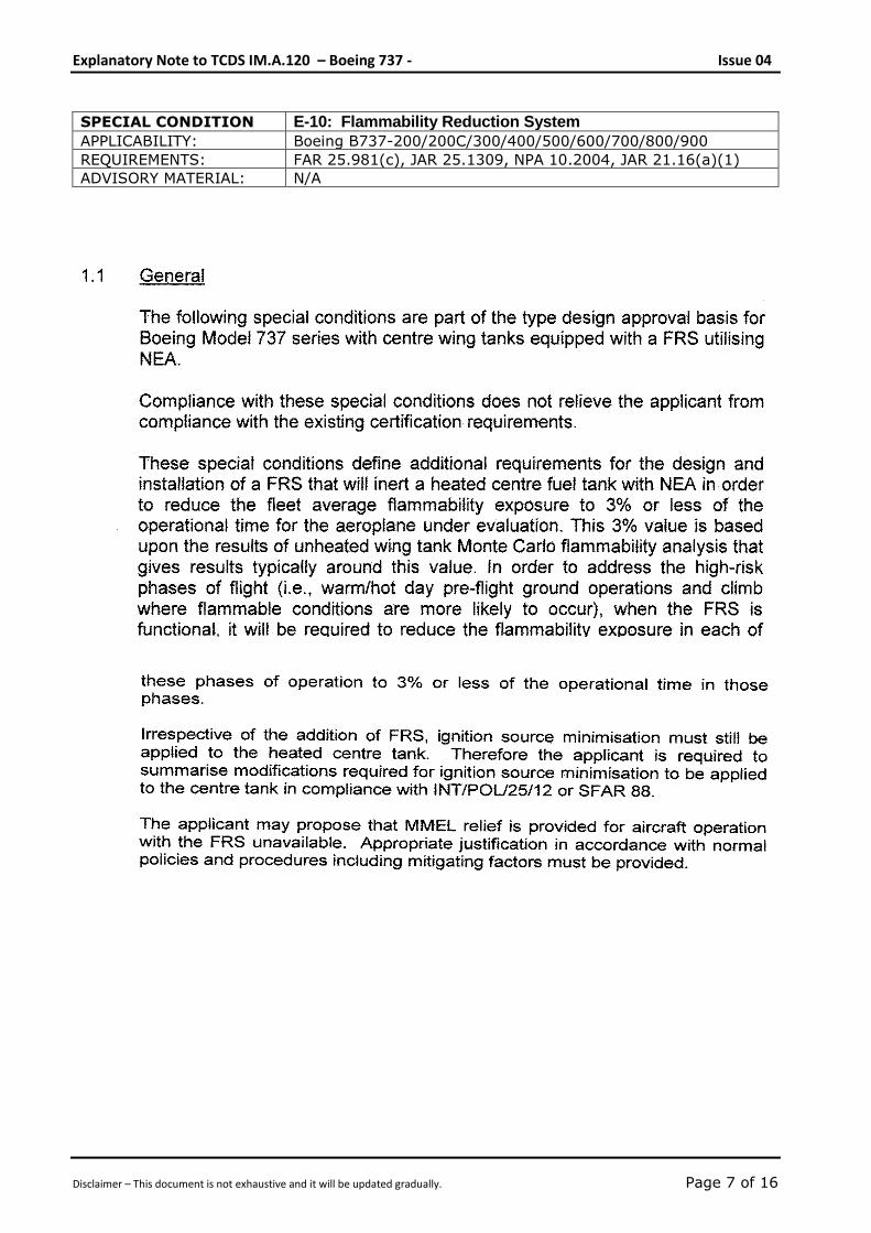
SPECIAL CONDITION E-10: Flammability Reduction System
APPLICABILITY: Boeing B737-200/200C/300/400/500/600/700/800/900
REQUIREMENTS: FAR 25.981(c), JAR 25.1309, NPA 10.2004, JAR 21.16(a)(1) ADVISORY MATERIAL: N/A
Explanatory Note to TCDS IM.A.120 – Boeing 737 - Issue 04
Disclaimer – This document is not exhaustive and it will be updated gradually. Page 8 of 16
Explanatory Note to TCDS IM.A.120 – Boeing 737 - Issue 04
Disclaimer – This document is not exhaustive and it will be updated gradually. Page 9 of 16
Explanatory Note to TCDS IM.A.120 – Boeing 737 - Issue 04
Disclaimer – This document is not exhaustive and it will be updated gradually. Page 10 of 16
Explanatory Note to TCDS IM.A.120 – Boeing 737 - Issue 04
Disclaimer – This document is not exhaustive and it will be updated gradually. Page 11 of 16
Explanatory Note to TCDS IM.A.120 – Boeing 737 - Issue 04
Disclaimer – This document is not exhaustive and it will be updated gradually. Page 12 of 16
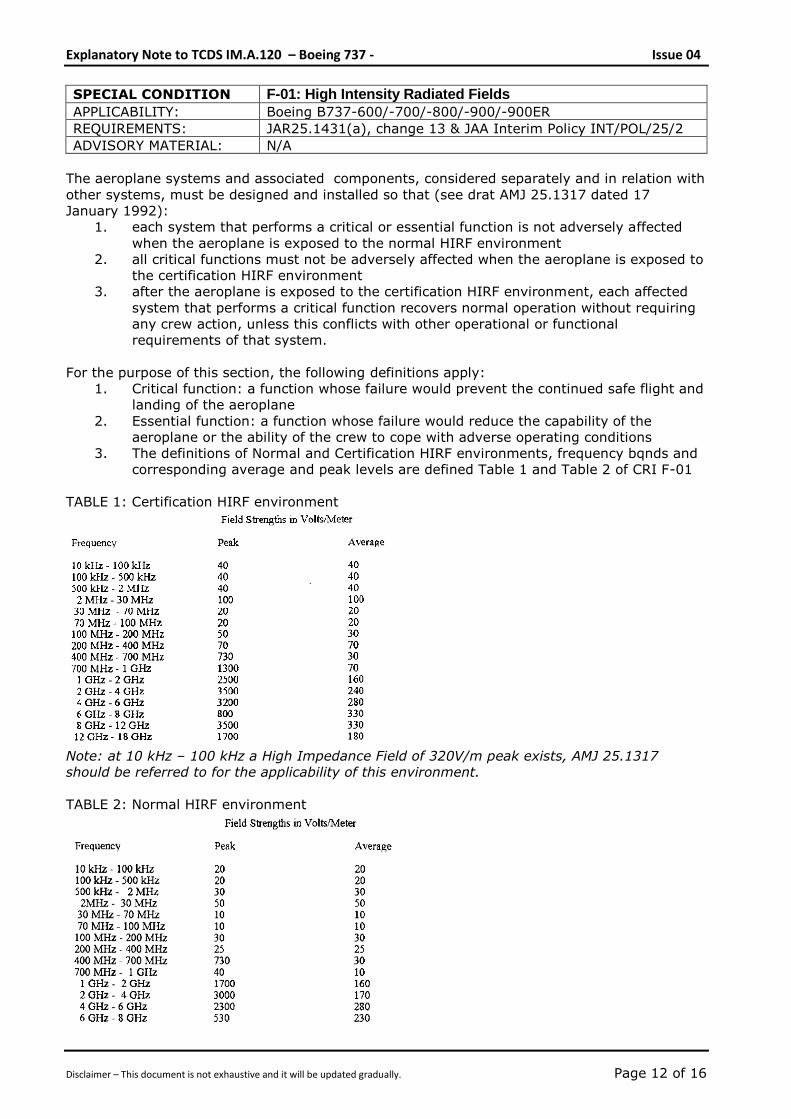
SPECIAL CONDITION F-01: High Intensity Radiated Fields
APPLICABILITY: Boeing B737-600/-700/-800/-900/-900ER
REQUIREMENTS: JAR25.1431(a), change 13 & JAA Interim Policy INT/POL/25/2 ADVISORY MATERIAL: N/A
The aeroplane systems and associated components, considered separately and in relation with
other systems, must be designed and installed so that (see drat AMJ 25.1317 dated 17
January 1992):
1. each system that performs a critical or essential function is not adversely affected
when the aeroplane is exposed to the normal HIRF environment
2. all critical functions must not be adversely affected when the aeroplane is exposed to
the certification HIRF environment
3. after the aeroplane is exposed to the certification HIRF environment, each affected
system that performs a critical function recovers normal operation without requiring
any crew action, unless this conflicts with other operational or functional
requirements of that system.
For the purpose of this section, the following definitions apply:
1. Critical function: a function whose failure would prevent the continued safe flight and
landing of the aeroplane
2. Essential function: a function whose failure would reduce the capability of the
aeroplane or the ability of the crew to cope with adverse operating conditions
3. The definitions of Normal and Certification HIRF environments, frequency bqnds and
corresponding average and peak levels are defined Table 1 and Table 2 of CRI F-01
TABLE 1: Certification HIRF environment
Note: at 10 kHz – 100 kHz a High Impedance Field of 320V/m peak exists, AMJ 25.1317
should be referred to for the applicability of this environment.
TABLE 2: Normal HIRF environment
Explanatory Note to TCDS IM.A.120 – Boeing 737 - Issue 04
Disclaimer – This document is not exhaustive and it will be updated gradually. Page 13 of 16
SPECIAL CONDITION F-02: Protection from the effects of Lightning strike; direct effects
APPLICABILITY: Boeing B737-600/-700/-800/-900/-900ER
REQUIREMENTS: JAR 25X899; ACJ 25X899 and JAA INT/POL/25/03 ADVISORY MATERIAL: N/A
The lightning current characteristics defined in table 1 and 2 of ACJ 25X899 do not line
up with the latest current models as specified in the internationally agreed SAE
Committee AE4L revision B and Culham CLM-R163 documents SC JAA/737-700/SC/F-
02.
For compliance with JAR 25X899, the zoning and current voltage waveforms as
specified in FAA AC20-53A shall be used in lieu of those specified in tables 1 and 2 of
ACJ 25X899.
In addition to the FAA AC, an additional 0.5 m zone 2 extension inboard of the existing
zone 1 should be considered (wing and empennage tips)
Explanatory Note to TCDS IM.A.120 – Boeing 737 - Issue 04
Disclaimer – This document is not exhaustive and it will be updated gradually. Page 14 of 16
SPECIAL CONDITION F-03: Protection from the effects of Lightning Srike; indirect effects
APPLICABILITY: Boeing B737-600/-700/-800/-900/-900ER
REQUIREMENTS: JAR25.581 ; 25X899 ; 25.954 ; 25.1309 and JAA INT/POL/25/4 ADVISORY MATERIAL: N/A
Each system whose failure to function properly would prevent the continued safe flight and
landing of the aircraft, must be designed and installed to ensure that the aircraft can perform
its intended function during and after exposure to lightning.
Each system whose failure to function properly would reduce the capacity of the aeroplane or
the ability of the flight crew to cope with adverse operating conditions must be designed and
installed to ensure that it can perform its intended function after exposure to lightning.
The lightning strike models to be used for system justification shall be as described in FAA AC
20-136 dated March 5, 1990.
Explanatory Note to TCDS IM.A.120 – Boeing 737 - Issue 04
Disclaimer – This document is not exhaustive and it will be updated gradually. Page 15 of 16
SPECIAL CONDITION H-01: Enhanced airworthiness programme for aeroplane systems – ICA on EWIS
APPLICABILITY: Boeing B717, B727, B737, B747, B757, B767, B777, DC-10,
MD11, DC-8, DC-9, MD80, MD90 (all FAR26.11 affected
models)
REQUIREMENTS: Part 21A.16B(a)(3), 21A.3B(c )(1), CS25.1529 & Appendix H ADVISORY MATERIAL: AMC 25 Subpart H
Add to: Appendix H Instructions for Continued Airworthiness
H25.5 Electrical Wiring Interconnection Systems Instructions for Continued
Airworthiness
The applicant must prepare Instructions for Continued Airworthiness (ICA) applicable to
Electrical Wiring Interconnection System (EWIS) as defined below that include the following:
Maintenance and inspection requirements for the EWIS developed with the use of an enhanced
zonal analysis procedure (EZAP) that includes:
a. Identification of each zone of the aeroplane.
b. Identification of each zone that contains EWIS.
c. Identification of each zone containing EWIS that also contains combustible materials.
d. Identification of each zone in which EWIS is in close proximity to both primary and back-up
hydraulic, mechanical, or electrical flight controls and lines.
e. Identification of –
• Tasks, and the intervals for performing those tasks, that will reduce the likelihood of
ignition sources and accumulation of combustible material, and
• Procedures, and the intervals for performing those procedures, that will effectively clean
the EWIS components of combustible material if there is not an effective task to reduce
the likelihood of combustible material accumulation.
f. Instructions for protections and caution information that will minimize contamination and
accidental damage to EWIS, as applicable, during the performance of maintenance,
alteration, or repairs.
The ICA must be in the form of a document appropriate for the information to be provided, and
they must be easily recognizable as EWIS ICA.
For the purpose of this Appendix H25.5, the following EWIS definition applies:
(a) Electrical wiring interconnection system (EWIS) means any wire, wiring device, or
combination of these, including termination devices, installed in any area of the aeroplane
for the purpose of transmitting electrical energy, including data and signals between two
or more intended termination points. Except as provided for in subparagraph (c) of this
paragraph, this includes:
(1) Wires and cables.
(2) Bus bars.
Explanatory Note to TCDS IM.A.120 – Boeing 737 - Issue 04
Disclaimer – This document is not exhaustive and it will be updated gradually. Page 16 of 16
Special Condition H-01 continued
(3) The termination point on electrical devices, including those on relays, interrupters,
switches, contactors, terminal blocks, and circuit breakers and other circuit
protection devices.
(4) Connectors, including feed-through connectors.
(5) Connector accessories.
(6) Electrical grounding and bonding devices and their associated connections.
(7) Electrical splices.
(8) Materials used to provide additional protection for wires, including wire insulation,
wire sleeving, and conduits that have electrical termination for the purpose of
bonding.
(9) Shields or braids.
(10) Clamps and other devices used to route and support the wire bundle.
(11) Cable tie devices.
(12) Labels or other means of identification.
(13) Pressure seals.
(b) The definition in subparagraph (a) of this paragraph covers EWIS components inside
shelves, panels, racks, junction boxes, distribution panels, and back-planes of equipment
racks, including, but not limited to, circuit board back-planes, wire integration units and
external wiring of equipment.
(c) Except for the equipment indicated in subparagraph (b) of this paragraph, EWIS
components inside the following equipment, and the external connectors that are part of
that equipment, are excluded from the definition in subparagraph (a) of this paragraph:
(1) Electrical equipment or avionics that is qualified to environmental conditions and
testing procedures when those conditions and procedures are -
(i) Appropriate for the intended function and operating environment, and
(ii) Acceptable to the Agency.
(2) Portable electrical devices that are not part of the type design of the aeroplane.
This includes personal entertainment devices and laptop computers.
(3) Fibre optics.
-- END --