Embed Size (px)
Citation preview
Simulation Modelling Practice and Theory 18 (2010) 407–415
Contents lists available at ScienceDirect
Simulation Modelling Practice and Theory
journal homepage: www.elsevier .com/ locate/s impat
Experimentation and performance analysis of multi-interfaced mobilerouter scheme
Xiaohua Chen a, Hongke Zhang a, Yao-Chung Chang b, Han-Chieh Chao a,c,d,*
a School of Electronics and Information Engineering, Beijing Jiaotong University, Beijing 100044, PR Chinab Department of Computer Science and Information Engineering, National Taitung University, Taitung, Taiwanc Institute of Computer Science & Information Engineering and Department of Electronic Engineering, National Ilan University, I-Lan, Taiwand Department of Electrical Engineering, National Dong Hwa University, Hualien, Taiwan
a r t i c l e i n f o a b s t r a c t
Article history:Available online 20 September 2009
Keywords:NEMOMultiple interfacesHandoverPerformance analysis
1569-190X/$ - see front matter � 2009 Elsevier B.Vdoi:10.1016/j.simpat.2009.09.005
* Corresponding author. Address: Institute of CoUniversity, College of EECS, No. 1, Sec. 1, Shenlung
E-mail address: [email protected] (H.-C. Chao).
Network mobility (NEMO) aims providing seamless Internet connectivity of the wholemobile network that consists of mobile routers (MRs) and mobile network nodes (MNNs).The network moves around along with vehicles as a whole. According to NEMO basic sup-port protocol (NEMO BSP), only one primary care of address (CoA) of MR can be registeredwith home agent, which will affect the handover performance. As an extension of NEMOBSP, multiple care of addresses (MCoA) registration scheme was proposed as Internet-draftand has received extensive researches.
This paper studies the Internet connectivity of mobile router (MR) on the basis statedabove; MR is equipped with WLAN, CDMA and GPRS interfaces simultaneously. Concretely,a smooth handover algorithm is proposed and experimented on our platform successfully;round trip time (RTT) of each link and the handover process between different interfacesare analyzed, respectively. Furthermore, the service disruption time and packet loss ratioperformances are also compared between uni-interfaced MR scheme of NEMO BSP andscheme proposed in this paper, and the results indicate that multi-interfaced scheme notonly supports large area movement across heterogeneous networks of MR, it also providesa seamless handover with no packet loss and little service disruption time.
� 2009 Elsevier B.V. All rights reserved.
1. Introduction
With the increasing demand for seamless Internet connectivity of mobile hosts and mobile networks, the internet engi-neering task force (IETF) has specified protocols for host mobility (MIPv6 [1]) and network mobility (NEMO [2]).
NEMO BSP is concerned with managing the mobility of an entire network. The application scenario is public transporta-tion, such as trains and buses [3]. NEMO BSP is based on MIPv6 with minimal extensions. Therefore, the handover mecha-nism of a mobile router (MR) is essentially the same as that of mobile node (MN) in MIPv6. In NEMO BSP, Mobile Routerserves as a gateway; a permanent address called home address (HoA) is obtained on the home link as an identifier of MR.When MR moves away, it acquires a care of address (CoA) from the access router (AR) in foreign network. MR sends bindingupdate (BU) message to its home agent (HA) located in the home network, binding the CoA with the HoA. HA replies a bind-ing acknowledgement (BA) message. After the binding process, a bi-directional tunnel is established between MR and HA.Packets from corresponding node (CN) with the destination of MR’s HoA are directly routed to HA, and HA are in charge
. All rights reserved.
mputer Science & Information Engineering and Department of Electronic Engineering, National IlanRoad, I-Lan 260, Taiwan. Tel.: +886 3 9357400x251; fax: +886 3 9354238.
408 X. Chen et al. / Simulation Modelling Practice and Theory 18 (2010) 407–415
of rerouting all packets to the CoA of MR through tunnel. Mobile network nodes (MNN) in the mobile network have perma-nent addresses taken from mobile network prefix (MNP) advertised on MR’s ingress interface, and packets intended to ororiginated from the MNNs are encapsulated in the tunnel.
Recently, various multihoming [4] issues have been presented in the NEMO Working Group. Multihoming is necessary toprovide constant access to Internet and to enhance the overall connectivity of hosts and mobile network [5]. In mobile envi-ronments, scarce bandwidth, frequent failures, and limited coverage areas of different network technologies particularlymotivate multihoming. For example, wireless local area networks (WLAN) are the most widely used local wireless networksystem in schools, offices, airports, etc. WLAN can provide bit rate up to 11 Mbit/s based on IEEE802.11b, while its coveragearea, known as hot spot, is too small, users cannot leave the hot spot until all transmissions are complete. On the other hand,CDMA and GPRS networks provide high mobility and ‘‘always on” connectivity for mobile users. However, their data ratesare much lower than that of WLAN. Multihoming technology can augment the Internet connectivity and enable users tochoose the preferred technology in terms of delay, bandwidth, etc. Tsukada et al. [6] and Paik et al. [7] realized the multih-omed mobile network by access Internet simultaneously with multiple mobile routers, each MR is equipped with only onekind of interface, and the dynamic management scheme of multihomed mobile network was proposed. The motivations andthe benefits of multihoming are described and illustrated through a number of scenarios in [8]. Wakikawa et al. [9] illus-trated the research results of network mobility in WIDE project of Keio University, in their scheme only WLAN and CDMAinterfaces are equipped on MR, and they cannot be used simultaneously. Furthermore, the downlink and uplink parametersof CDMA interface is tested and described. Shima et al. [10] gives the handover scheme of multi-interfaced MR in networkmobility, no relative analysis are described anymore.
In this paper, we propose a multi-interfaced MR scheme and make experimentation on our platform. In this scheme, theMR is equipped with WLAN, GPRS and CDMA interfaces simultaneously. An inter-interfaces handover algorithm is proposed,and the performance during media handover is measured and analyzed.
The remainder of this paper is organized as follows: In Section 2, the multiple interface scheme of MR is described, includ-ing MCoA registration scheme, media handover decision and the interface handover operation. The experimentation over-view and results are presented and analyzed in Section 3. Then, in Section 4, we give the performance analysis of servicedisruption time and packet loss ratio, and the comparison with uni-interfaced MR in NEMO basic support protocol is alsoillustrated. Finally, we provide concluding remarks.
2. Multiple interfaces scheme of mobile router
In this section, we will first introduce the MCoA registration scheme, and then the multiple interfaces scheme extendedfor MR is described, including the handover decision and interface handover operation.
2.1. Multiple care of addresses registration
According to MIPv6, mobile node (MN) may have several care of addresses, but only one CoA termed the primary CoA canbe registered with its HA and CN. When MN is equipped with multiple interfaces and multiple CoAs are configured, there aremultiple bindings to its HA. Ref. [11] was proposed as a NEMO extension to register multiple CoAs to a same home address(HoA) of MR. For doing so, a Binding Unique Identifier (BID) must be carried in each BU for the receiver. HA keeps bindingscorresponding to the same HoA and distinguishes them by different BIDs as described in [11]. In order to maintain multiplebindings and make all the interfaces useful simultaneously when attaches to both foreign and home links, MN sets the ‘H’flag in the BID mobility option illustrated in Fig. 2. There are also additional processes of Proxy Neighbor Discovery Protocol[11,13].
MCoA scheme aims to create multiple bi-directional tunnels between MR and HA. When the MR is equipped with WLAN,CDMA and GPRS interfaces simultaneously, the MCoA registration procedure is shown in Fig. 1.
As shown in Fig. 1, each of MR’s interfaces configures a CoA and sends Binding Update (BU) message to HA. Each BU mes-sage contains a BID for each CoA, and all the CoAs are bound to MR’s HoA. HA replies BA messages containing different BIDsub-options, respectively. Then three bi-directional tunnels are established between MR and HA.
2.2. Inter-interfaces handover decision mechanism
Generally, when WLAN is not available, MR connects to Internet by CDMA/GPRS networks in regional area according tosignal strength scanned. When WLAN network is available and the scanned signal strength is higher than the threshold Sth,WLAN will be used due to its bandwidth advantage.
In order to enable seamless handover between different interfaces, we extend the BID sub-option, which is shown inFig. 2.The BID sub-option is included in BU, BA messages, etc.
In Fig. 2, ‘‘BID” has already been defined in [11] to identify different bindings. We add ‘‘D” flag and ‘‘pre_default_BID” flagon BID sub-option defined in [11]. ‘‘D” is used to indicate the occurrence of interface handover, while ‘‘pre_default_BID” isused to store the BID of the interface used before. The interface handover decision of MR is shown in Fig. 3, and the detailedworking process of BID sub-option is described in the following section.
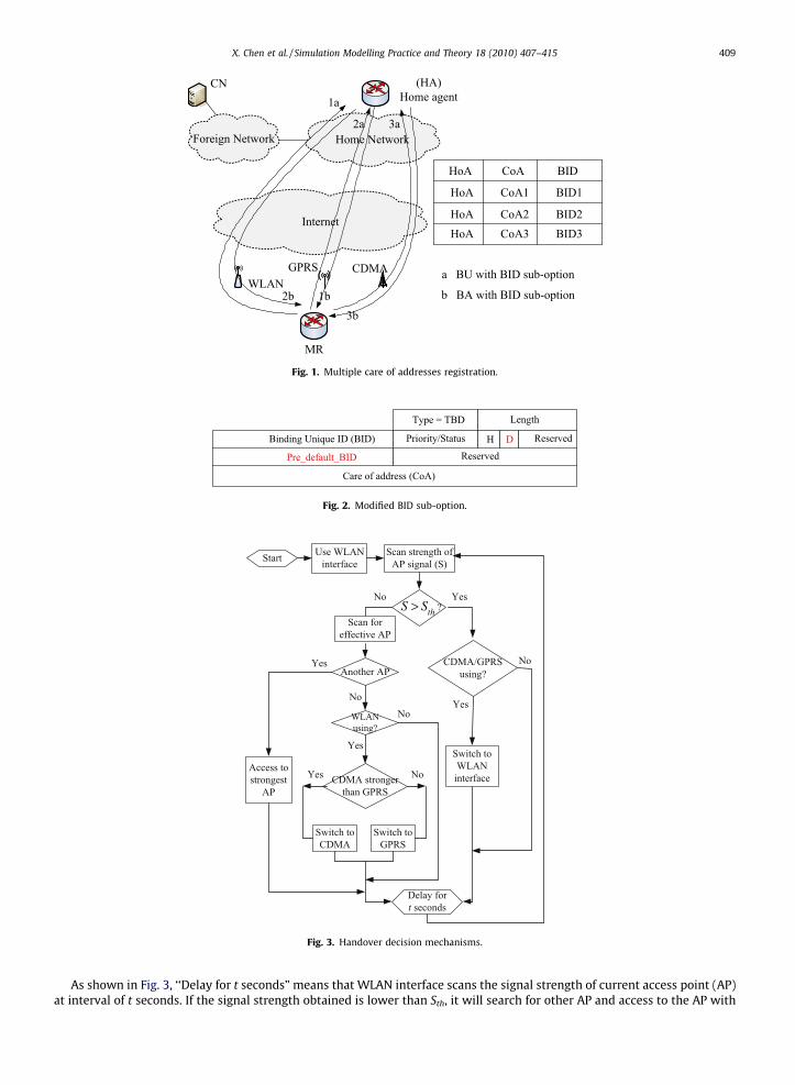
Fig. 1. Multiple care of addresses registration.
Fig. 2. Modified BID sub-option.
?thS S>
t
Fig. 3. Handover decision mechanisms.
X. Chen et al. / Simulation Modelling Practice and Theory 18 (2010) 407–415 409
As shown in Fig. 3, ‘‘Delay for t seconds” means that WLAN interface scans the signal strength of current access point (AP)at interval of t seconds. If the signal strength obtained is lower than Sth, it will search for other AP and access to the AP with
410 X. Chen et al. / Simulation Modelling Practice and Theory 18 (2010) 407–415
strongest signal. If no effective AP exists, MR will switch to CDMA/GPRS interface according to the respective signal strength.Then after delay of t seconds, WLAN interface scans the signal strength another time.
2.3. Interface handover operation
In our scheme, layer 2-handover trigger module is independent from the MCoA NEMO protocol. We allocate a field in theshared memory between the trigger module and MCoA NEMO protocol to store the ‘‘interface index” of current interface inuse. ‘‘interface index” is the interface identifier in layer 2.
(1) If traffic switches from one interface to another one according to the handover mechanism, the layer 2-handover trig-ger module sends a message to the shared memory, informing the ‘‘interface index” of the new interface in use, whichwill be read by the MCoA NEMO protocol.
(2) On receiving the informing message, MR changes the ‘‘BID” sub-option and ‘‘priority” field and notifies HA the inter-face handover through the operation in MCoA NEMO protocol.
There is only one BID for one interface, so MR can notify HA the change of interface by the change of BID. Because BUmessages are refreshed at a fixed interval, in order to avoid frequent and repeated operations of HA, the new added ‘‘D”bit in extended BID sub-option is used to indicate the occurrence of interface handover. ‘‘pre_default_BID” field is used tostore the BID in BU sent before. If ‘‘BID” used in the new BU and BU sent before are same with each other, D is set to 0, whichmeans no interface handover occur.
Otherwise, if ‘‘pre_default_BID” and ‘‘BID” option are different, D is set to 1, which means another interface is selected.On receiving BU message from MR, HA will check ‘‘D” bit. If D = 0, HA will do nothing to the ‘‘pre_default_BID” field. Other-
wise when D = 1, HA compares the ‘‘pre_default_BID” and ‘‘BID” fields, reading the ‘‘BID” field, and set the priority of theinterface corresponding to the new ‘‘BID” higher than the other two interfaces. Then all the packets will be transmittedby this new interface.
All the handover processes described above are transparent to applications upperlayer. We can measure the packetsdelivery performance during interface handovers to evaluate the scheme.
3. Experimentation results
This section shows the overview of our system and the compatibility of WLAN, CDMA and GPRS networks with the mobil-ity protocol.
Please note that in our experimentation, we set up a interaction window so that handover can be triggered manually. Thishandover operation does not affect the application upper layer so that we can measure the service disruption time and pack-et loss performance during media handover conveniently.
3.1. Overview of the experimentation
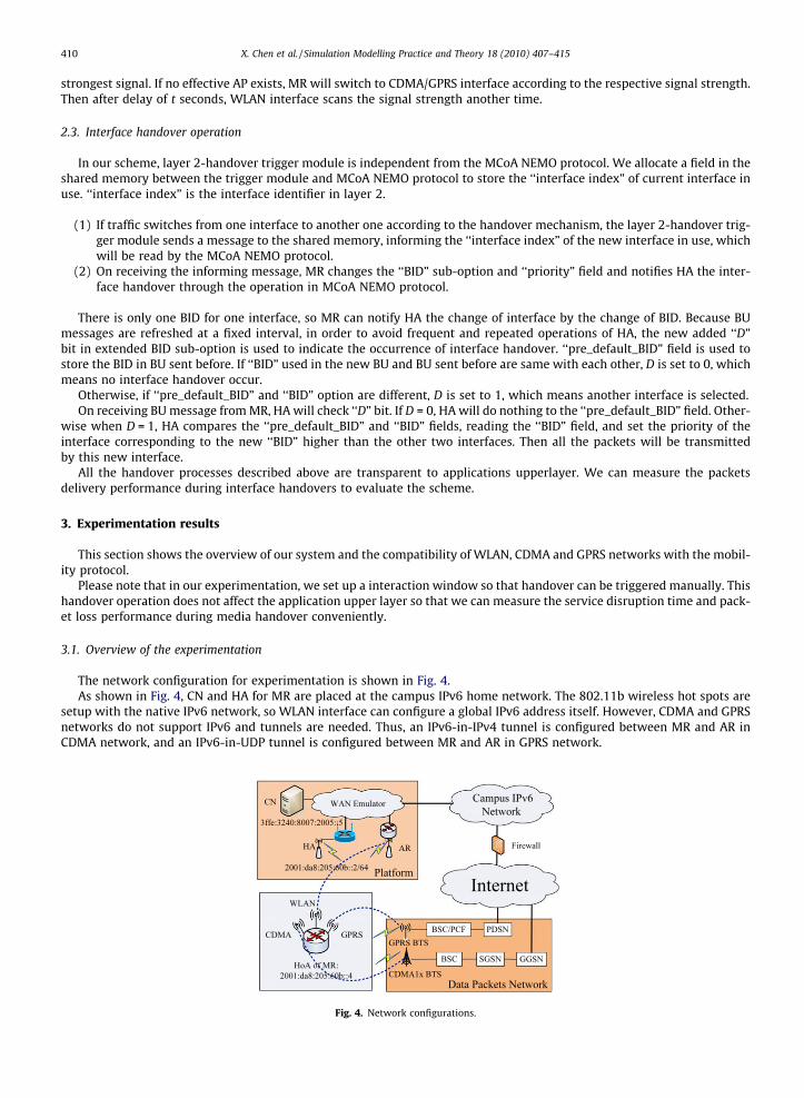
The network configuration for experimentation is shown in Fig. 4.As shown in Fig. 4, CN and HA for MR are placed at the campus IPv6 home network. The 802.11b wireless hot spots are
setup with the native IPv6 network, so WLAN interface can configure a global IPv6 address itself. However, CDMA and GPRSnetworks do not support IPv6 and tunnels are needed. Thus, an IPv6-in-IPv4 tunnel is configured between MR and AR inCDMA network, and an IPv6-in-UDP tunnel is configured between MR and AR in GPRS network.
Fig. 4. Network configurations.
X. Chen et al. / Simulation Modelling Practice and Theory 18 (2010) 407–415 411
All the network entities mentioned above run on the platform of Fedora Core2, the Kernel is Linux-2.6.8.1, and the pro-tocol is NEMO-0.1-MCoA. CN is equipped with a 100 Mbps Ethernet adapter, and HA is equipped with a 100 Mbps Ethernetadapter and a ‘‘Cisco Aironet 1200” access point (AP). MR is PP04L P4-M DELL notebook PC with 1.8 G CPU, 30 G hard disk,and 256 M memories. The ingress interface of MR is ‘‘Cisco Aironet 350” wireless card. The parameters of WLAN, CDMA andGPRS interfaces are listed in Table 1.
Application prepared for the experimentation is ping6 messages. The packets delivery performance is evaluated by themeasurement of the round trip time (RTT) of different links between MR and CN established by WLAN, CDMA and GPRSinterfaces, respectively. The RTT values between MR and CN by sending 56 bytes ICMPv6 echo request and reply messagesto CN with ‘‘ping6” program via different interfaces are listed in Table 2 in detail.
From Table 2 we can see that WLAN interface performs best on our testbed, GPRS interface is not so good due to its datarate limitation.
3.2. Handover between WLAN and CDMA
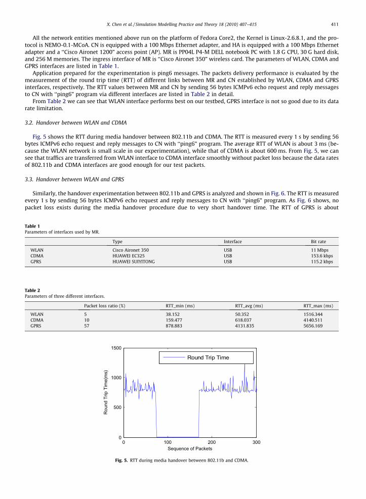
Fig. 5 shows the RTT during media handover between 802.11b and CDMA. The RTT is measured every 1 s by sending 56bytes ICMPv6 echo request and reply messages to CN with ‘‘ping6” program. The average RTT of WLAN is about 3 ms (be-cause the WLAN network is small scale in our experimentation), while that of CDMA is about 600 ms. From Fig. 5, we cansee that traffics are transferred from WLAN interface to CDMA interface smoothly without packet loss because the data ratesof 802.11b and CDMA interfaces are good enough for our test packets.
3.3. Handover between WLAN and GPRS
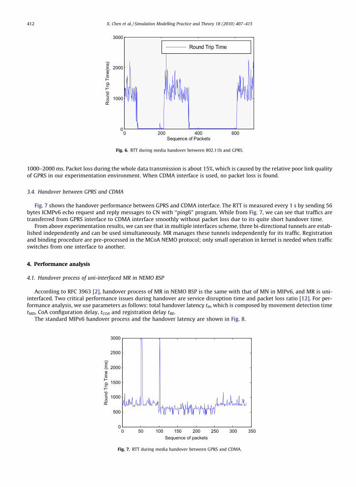
Similarly, the handover experimentation between 802.11b and GPRS is analyzed and shown in Fig. 6. The RTT is measuredevery 1 s by sending 56 bytes ICMPv6 echo request and reply messages to CN with ‘‘ping6” program. As Fig. 6 shows, nopacket loss exists during the media handover procedure due to very short handover time. The RTT of GPRS is about
Table 1Parameters of interfaces used by MR.
Type Interface Bit rate
WLAN Cisco Aironet 350 USB 11 MbpsCDMA HUAWEI EC325 USB 153.6 kbpsGPRS HUAWEI SUIYITONG USB 115.2 kbps
Table 2Parameters of three different interfaces.
Packet loss ratio (%) RTT_min (ms) RTT_avg (ms) RTT_max (ms)
WLAN 5 38.152 50.352 1516.344CDMA 10 159.477 618.037 4140.511GPRS 57 878.883 4131.835 5656.169
0 100 200 3000
500
1000
1500
Sequence of Packets
Rou
nd T
rip T
ime(
ms)
Round Trip Time
Fig. 5. RTT during media handover between 802.11b and CDMA.
0 200 400 6000
1000
2000
3000
Sequence of Packets
Rou
nd T
rip T
ime(
ms)
Round Trip Time
Fig. 6. RTT during media handover between 802.11b and GPRS.
412 X. Chen et al. / Simulation Modelling Practice and Theory 18 (2010) 407–415
1000–2000 ms. Packet loss during the whole data transmission is about 15%, which is caused by the relative poor link qualityof GPRS in our experimentation environment. When CDMA interface is used, no packet loss is found.
3.4. Handover between GPRS and CDMA
Fig. 7 shows the handover performance between GPRS and CDMA interface. The RTT is measured every 1 s by sending 56bytes ICMPv6 echo request and reply messages to CN with ‘‘ping6” program. While from Fig. 7, we can see that traffics aretransferred from GPRS interface to CDMA interface smoothly without packet loss due to its quite short handover time.
From above experimentation results, we can see that in multiple interfaces scheme, three bi-directional tunnels are estab-lished independently and can be used simultaneously. MR manages these tunnels independently for its traffic. Registrationand binding procedure are pre-processed in the MCoA NEMO protocol; only small operation in kernel is needed when trafficswitches from one interface to another.
4. Performance analysis
4.1. Handover process of uni-interfaced MR in NEMO BSP
According to RFC 3963 [2], handover process of MR in NEMO BSP is the same with that of MN in MIPv6, and MR is uni-interfaced. Two critical performance issues during handover are service disruption time and packet loss ratio [12]. For per-formance analysis, we use parameters as follows: total handover latency tH, which is composed by movement detection timetMD, CoA configuration delay, tCOA and registration delay tRE.
The standard MIPv6 handover process and the handover latency are shown in Fig. 8.
0 50 100 150 200 250 300 3500
500
1000
1500
2000
2500
3000
Sequence of packets
Rou
nd T
rip T
ime
(ms)
Fig. 7. RTT during media handover between GPRS and CDMA.
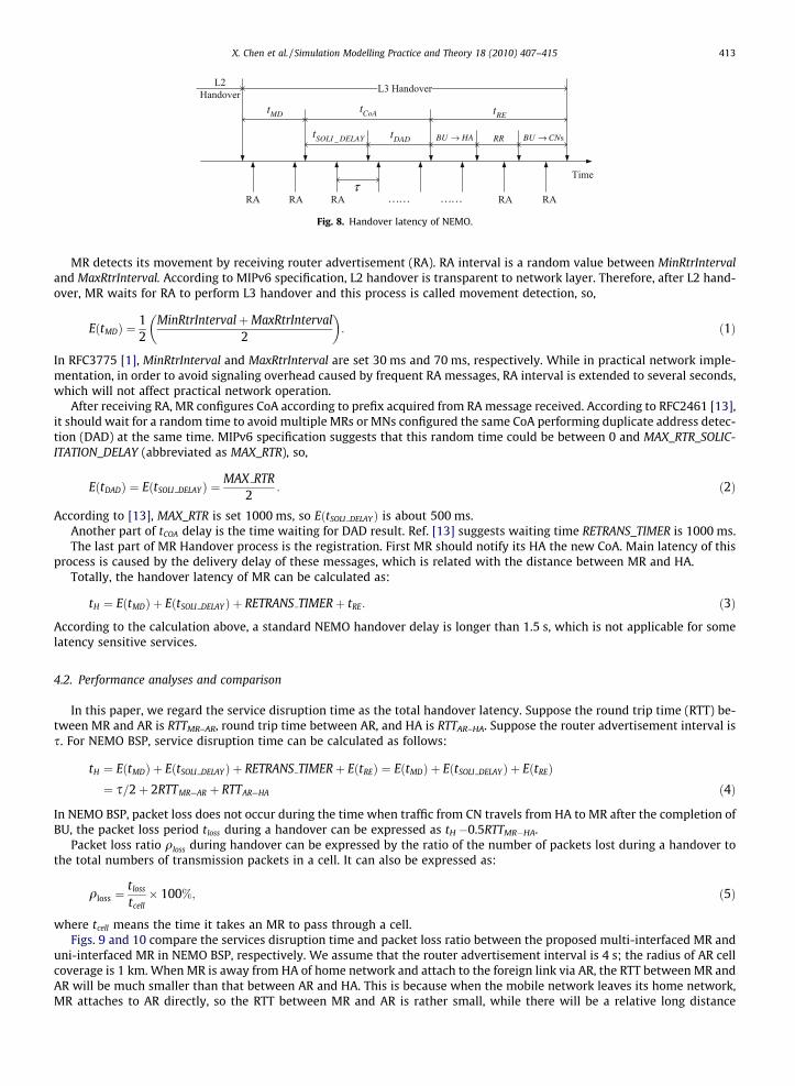
Fig. 8. Handover latency of NEMO.
X. Chen et al. / Simulation Modelling Practice and Theory 18 (2010) 407–415 413
MR detects its movement by receiving router advertisement (RA). RA interval is a random value between MinRtrIntervaland MaxRtrInterval. According to MIPv6 specification, L2 handover is transparent to network layer. Therefore, after L2 hand-over, MR waits for RA to perform L3 handover and this process is called movement detection, so,
EðtMDÞ ¼12
MinRtrIntervalþMaxRtrInterval2
� �: ð1Þ
In RFC3775 [1], MinRtrInterval and MaxRtrInterval are set 30 ms and 70 ms, respectively. While in practical network imple-mentation, in order to avoid signaling overhead caused by frequent RA messages, RA interval is extended to several seconds,which will not affect practical network operation.
After receiving RA, MR configures CoA according to prefix acquired from RA message received. According to RFC2461 [13],it should wait for a random time to avoid multiple MRs or MNs configured the same CoA performing duplicate address detec-tion (DAD) at the same time. MIPv6 specification suggests that this random time could be between 0 and MAX_RTR_SOLIC-ITATION_DELAY (abbreviated as MAX_RTR), so,
EðtDADÞ ¼ EðtSOLI DELAYÞ ¼MAX RTR
2: ð2Þ
According to [13], MAX_RTR is set 1000 ms, so EðtSOLI DELAYÞ is about 500 ms.Another part of tCOA delay is the time waiting for DAD result. Ref. [13] suggests waiting time RETRANS_TIMER is 1000 ms.The last part of MR Handover process is the registration. First MR should notify its HA the new CoA. Main latency of this
process is caused by the delivery delay of these messages, which is related with the distance between MR and HA.Totally, the handover latency of MR can be calculated as:
tH ¼ EðtMDÞ þ EðtSOLI DELAYÞ þ RETRANS TIMERþ tRE: ð3Þ
According to the calculation above, a standard NEMO handover delay is longer than 1.5 s, which is not applicable for somelatency sensitive services.
4.2. Performance analyses and comparison
In this paper, we regard the service disruption time as the total handover latency. Suppose the round trip time (RTT) be-tween MR and AR is RTTMR–AR, round trip time between AR, and HA is RTTAR–HA. Suppose the router advertisement interval iss. For NEMO BSP, service disruption time can be calculated as follows:
tH ¼ EðtMDÞ þ EðtSOLI DELAYÞ þ RETRANS TIMERþ EðtREÞ ¼ EðtMDÞ þ EðtSOLI DELAYÞ þ EðtREÞ¼ s=2þ 2RTTMR—AR þ RTTAR—HA ð4Þ
In NEMO BSP, packet loss does not occur during the time when traffic from CN travels from HA to MR after the completion ofBU, the packet loss period tloss during a handover can be expressed as tH �0.5RTTMR�HA.
Packet loss ratio qloss during handover can be expressed by the ratio of the number of packets lost during a handover tothe total numbers of transmission packets in a cell. It can also be expressed as:
qloss ¼tloss
tcell� 100%; ð5Þ
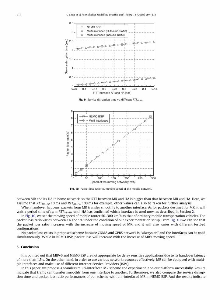
where tcell means the time it takes an MR to pass through a cell.Figs. 9 and 10 compare the services disruption time and packet loss ratio between the proposed multi-interfaced MR and
uni-interfaced MR in NEMO BSP, respectively. We assume that the router advertisement interval is 4 s; the radius of AR cellcoverage is 1 km. When MR is away from HA of home network and attach to the foreign link via AR, the RTT between MR andAR will be much smaller than that between AR and HA. This is because when the mobile network leaves its home network,MR attaches to AR directly, so the RTT between MR and AR is rather small, while there will be a relative long distance
0 50 100 150 200 250 3000
1
2
3
4
5
6
7
8
9
Speed of the moving network(Km/h)
Pac
ket
loss
rat
io(%
)
NEMO BSP
Multi-interfaced
Fig. 10. Packet loss ratio vs. moving speed of the mobile network.
0.05 0.1 0.15 0.2 0.25 0.3 0.35 0.4 0.450
0.5
1
1.5
2
2.5
3
3.5
RTT between AR and HA (sec)
Ser
vice
dis
rupt
ion
time
(sec
)
NEMO BSP
Multi-interfaced (Outbound Traffic)
Multi-interfaced (Inbound Traffic)
Fig. 9. Service disruption time vs. different RTTAR HA .
414 X. Chen et al. / Simulation Modelling Practice and Theory 18 (2010) 407–415
between MR and its HA in home network, so the RTT between MR and HA is bigger than that between MR and HA. Here, weassume that RTTMR—AR 10 ms and RTTAR—HA 100 ms for example, other values can also be taken for further analysis.
When handover happens, packets from MR transfer smoothly to another interface. As for packets destined for MR, it willwait a period time of tRE ¼ RTTMR—HA until HA has confirmed which interface is used now, as described in Section 2.
In Fig. 10, we set the moving speed of mobile router 50–300 km/h as that of ordinary mobile transportation vehicles. Thepacket loss ratio varies between 1% and 9% under the condition of our experimentation setup. From Fig. 10 we can see thatthe packet loss ratio increases with the increase of moving speed of MR, and it will also varies with different testbedconfigurations.
No packet loss exists in proposed scheme because CDMA and GPRS network is ‘‘always on” and the interfaces can be usedsimultaneously. While in NEMO BSP, packet loss will increase with the increase of MR’s moving speed.
5. Conclusion
It is pointed out that MIPv6 and NEMO BSP are not appropriate for delay sensitive applications due to its handover latencyof more than 1.5 s. On the other hand, in order to use various network resources effectively, MR can be equipped with multi-ple interfaces and make use of different Internet Service Providers (ISPs).
In this paper, we propose a seamless multi-interfaced MR scheme and experiment it on our platform successfully. Resultsindicate that traffic can transfer smoothly from one interface to another. Furthermore, we also compare the service disrup-tion time and packet loss ratio performances of our scheme with uni-interfaced MR in NEMO BSP. And the results indicate
X. Chen et al. / Simulation Modelling Practice and Theory 18 (2010) 407–415 415
that multi-interfaced scheme not only supports large area movement across heterogeneous networks of MR, it also providesa seamless handover with no packet loss and little service disruption time.
This scheme can also be applied to mobile node (MN) especially when it moves around in a large area range and make useof different Internet Service Provider (ISP).
Acknowledgements
This research is supported partly by the Cultivation Fund of the Key Scientific, Technical Innovation Project of China (No.706005) and National Ilan University.
References
[1] D. Johnson, C. Perkins, J. Arkko, Mobility Support in IPv6, RFC3775, 2004.[2] V. Devarapalli, R. Wakikawa, A. Petrescu, et al., Network Mobility (NEMO) Basic Support Protocol, RFC3963, 2005.[3] Eranga Perera, Vijay Sivaraman, Aruna Seneviratne, Survey on network mobility support, Mobile Computing and Communications Review 8 (2) (2005).[4] T. Ernst, N. Montavont, R. Wakikawa, C. Ng, K. Kuladinithi, Motivations and Scenarios for Using Multiple Interfaces and Global Addresses, draft-ietf-
monami6-multihoming-motivation-scenario-02.txt, July 2007.[5] N. Montavont, T. Ernst, T. Noel, Multihoming in nested mobile networking, in: SAINT 2004 Workshop, January 2004.[6] Manabu Tsukada, Thierry Ernst, Ryuji Wakikawa, et al., Dynamic management of multiple mobile routers, in: 13th IEEE International Conference on
Networks, Jointly held with the 2005 IEEE 7th Malaysia International Conference on Communication, 2005, pp. 6–12.[7] Eun Kyoung Paik, Ho-sik Cho, Thierry Ernst, et al., Load sharing and session preservation with multiple mobile routers for large scale network mobility,
in: Proceedings of the 18th International Conference on Advanced Information Networking and Application (AINA’04), vol. 1, 2004, pp. 393–398.[8] C. Ng, T. Ernst, E. Paik, M. Bagnulo, Analysis of Multihoming in Network Mobility Support, RFC4980, October 2007.[9] Ryuji Wakikawa, Tomoyoshi Yokota, Kazuyuki Tasaka, Keisuke Uehara, Experimentation of networked vehicle with multihomed mobile router, in: IEEE
62nd Conference on Vehicular Technology Conference (VTC-2005), vol. 1, 2005, pp. 334–338.[10] K. Shima, Y. Uo, N. Ogashiwa, S. Uda, Operational experiment of seamless handover of a mobile router using multiple care-of address registration,
Journal of Networks 1 (3) (2006) 23–30.[11] R. Wakikawa, T. Ernst, K. Nagami, V. Devarapalli, Draft-ietf-monami6-multiplecoa-14, Multiple Care-of Addresses Registration, May 28, 2009.[12] Hee-Dong Park, Dong-won Kum, Yong-Ha Kwon, Kang-Won Lee, and You-Ze Cho, IP mobility support with a multihomed mobile router, in: F. Boavida
et al. (Eds.): NETWORKING 2006, LNCS 3976, 2006, pp. 1144–1149.[13] T. Narten, E. Nordmark, W. Simpson, Neighbor Discovery for IP Version 6 (IPv6), RFC2461, December 1998.