Embed Size (px)
Citation preview

101
Structural End-./Earthquake Eng. Vol. 7. No. 1. 89s-100s. April 1990Japan Society of Civil Engineers (Proc. of JSCE No. 416/1-13)
EXPERIMENTAL STUDY ON THE OUT-OF-PLANE BUCKLING
STRENGTH OF STEEL ARCHES WITH OPEN CROSS SECTION
By Tsu tome SAKA TA* and Ta tsuro SAKIMO TO**
Experiments for total of 11 specimens are carried out to observe the behavior of elas-
to-plastic out-of-plane buckling of the arch structures with open cross section which are
subjected to uniform vertical load. The effects of several factors on ultimate strength
are investigated, that is, slenderness ratios of arch rib, load directions, types of brac-ing system and braced length ratios. The experimental results are compared with the
theoretical ones. In general, the theoretical predictions show good correspondence with
the experimental results in ultimate strength and buckling modes and so on. Validity and
efficiency of the theoretical procedure are confirmed.
Keywords: arch structure, out-of-plane buckling, ultimate strength, experimental study
1. INTRODUCTION
Several studies have been reported on the ultimate load-carrying capacities of arch structures which fail
by inelastic lateral instability, theoretically1)-7) and experimentally8). But the inelastic lateral buckling
strength of arch structures with open cross section which are subjected to uniform vertical load has not
been clarified sufficiently. One of the reasons for this is the difficulty to analyze the inelastic torsional behavior of the member with an open profile section.
The purposes of this experimental investigation are to provide the fundamental data concerning the
inelastic lateral instability of steel arches with open cross section, and to examine the validity of the
theoretical study presented previously by the writers9) . Since the ultimate strength of the arch structure
may be affected by the residual stress, initial lateral crookedness, the slenderness ratio of the arch rib,
the load direction, the arch configuration, the type of the bracing system, the braced length ratio and so
on, effects of these factors are discussed herein. The experimental results of specimens are compared with
the behaviors predicted by the theoretical computations. The observed ultimate strength are also compared
with the predictions obtained from the formula proposed by the writers in Ref. 7) for the ultimate strength
of arch structures with closed cross section.
2. EXPERIMENTAL PROGRAM
(1) Design of the model arch Nominal dimensions of the model arch are determined according to the following conditions
1) The model arch is a parabolic or circular one with two-hinged end conditions, and its structural
* Member of JSCE, M. Eng., Graduate student of Doctor Course, Kumamoto University (2-39-1 Kurokami Kumamoto, 860)
** Member of JSCE, Dr. Eng., Professor of Civil and Environmental Engineering, Kumamoto University
89s

102 T. SAKATA and T. SAKIMOTO
parameters are similar in proportion to those of existing actual bridges. 2) The slenderness ratio of the arch rib is determined so that the arch fails owing to an overall
instability in the elasto-plastic range.
3) The cross section of the arch rib is a welded H-section and its size is large enough to be able to measure accurately the residual stress distribution.
4) The component plates of the cross section should not fail owing to a local buckling prior to the overall instability of the arch.
5) The vertical maximum load must be less than the maximum capacity of an available hydraulic jack, which is 30 tons by itself and 60 tons by using a lever beam.
The nominal dimensions of the model arches are shown in Table 1 and Fig. 1, where the radius R and the
central angle of the arch are defined only for the circular arch.
(2) Lateral bracing members for twin arches The lateral deformation of the arch is characterized by the interaction between the lateral deflection and
the torsional deformation. So, three types of bracing systems, shown in Fig. 2, are designed for specimens
Table 1 Nominal Dimensions and Structural Properties of the Model Arch.
Fig. 1 Dimensions of the Model Arch,
Side-View
Cross-Section
Single
arch rib
Twin
arch rib
Fig, 2 Dimensions and Arrangements of bracing Members.
(unit in mm)
p typeL type X type
Fig, 3 Bracing System.
90s

Experimental Study on the Out-of- Plane Buckling Strength of Steel Arches with Open Cross Section 103
of twin arches to examine their
efficiency. Type P, is transverse
beams of rectangular cross section
and mainly resists torsion of the arch
rib. Type L, is also transverse
beams of rectangular cross section
but mainly resists lateral bending of
the arch rib. These two types of
transverse beams are just different
in the locating direction of the strong
axis of the cross section in relation
to the arch axis direction as shown in
Fig. 2. Type X, consisting of double
diagonals in combination with trans-
verse bars, resists lateral bending
of the arch as a double warren truss
system.
Dimensions of the bracing member
of type P are decided so that it can
enhance the torsional rigidity of the
arch rib, that is, the ratio of the flexural rigidity of the transverse beam, EIb, to the torsional rigidity of
the single arch rib, GI, is nearly 40. In the case of type L, the ratio of the flexural rigidity of the
transverse beam, EIb, to the flexural rigidity of the single arch rib about lateral bending Em, is
approximately 1. In the case of type X, the slenderness ratio of the diagonal member is determined to be
small enough to avoid its premature buckling prior to the overall failure of the arch. Dimensions of the
bracing members are shown in Fig, 2. The arrangement and numbers of the bracing members used are
shown in Fig. 3.
(3) Notation of the model The names of the specimens are summarized in Table 2. The letters in the notations, for example
P-296-L7-V, refer to the configuration (P: parabolic, C: circular), the slenderness ratio of the single
arch rib, the type and the number of bracing members and the load direction (V: vertical, T: tilting), in
this order. Each specimen is planned to test according to the following intentions
The slenderness ratios of the single arch models are varied as 198, 156 and 115 to examine the effect on
the ultimate strength, and specimens No. 4, No. 6 and No. 11 are prepared to examine the effect of the
loading direction (tilting load shown in Fig, 5) on the ultimate strength. The effect of the configuration of
arch rib is studied by specimens No. 1 and No. 2. The influence of the bracing system on the ultimate
strength of twin arch models are studied by specimens No. 7-No. 11. The specimens No. 7 and No. 8 are to
observe the effect of the flexural rigidity of transverse beam about the x-axis and y-axis, (axes are shown
in Fig. 1). The braced length ratio B is defined as the ratio of the arch rib length braced with lateral
members to the total arch rib length. The B values of specimens No. 9 and No. 10 are varied as 0.75 and
0.50, respectively, in order to observe the effect of the braced length ratio B on the ultimate strength of twin arch models.
(4 ) Preliminary tests The average values of standard tensile coupon tests are shown in Table 3. The measured values are used
for evaluating the model test data. Fig. 4 shows the residual stress distributions obtained from the measured values (by solid lines) and those (by broken lines) modified so as to satisfy the self-equilibrium
conditions as well as doubly symmetric conditions. The initial lateral crookedness for each specimen is
Table 2 List of Test Specimens.
Table 3 Mechanical Properties of the Material.
*The varlues given in parentheses indicate SI unit.
91s

104 T. SAKATA and T SAKIMOTO
carefully measured after setting the specimen on the test frame. The ratio of the maximum value to the arch
span and the shape of the initial lateral crookedness for each specimen are summarized in Table 4.
(5) Application of load The uniformly distributed vertical load is idealized by a group of eight concentrated loads as shown in
Fig. 5 and 6. The beams installed in the loading apparatus are connected mutually with hinges so as to be
free for rotation about both in-plane and out-of-plane directions.
Specimens of which names end with the letter T were tested under the tilting load condition shown in
Fig. 6 (b). For these specimens, the lateral displacement of the loading beam is restrained, as shown in
Fig. 7, to simulate the actual hanger load in a through-type bridge. Rest of specimens are tested under the
vertical load (Fig. 6 (a)) which means the case with a flexible deck in actual through-type bridges. The
magnitude of the individual concentrated load is checked by wire strain gages mounted on the individual
hanger.
(6) Measurements of strains and displacements
Fig. 4 Residual Stress Distributions.
-Measured value
-o-Modified value
Specimen
No. 1, No. 2
Specimen
No. 3, No. 4Specimen
No. 5, No. 6Specimen
No. 7-No. 11
Table 4 Initial Lateral Crookedness
Fig. 5 Loading Apparatus.
Fig. 6 Load Directions.
(a)Vertical Load
(b) Tilting Load
Fig. 7 Lateral Restraint for Loading Beams.
92s

Experimental Study on the Out-of-Plane Buckling Strength of Steel iln hes with Open Cross Section 105
In order to obtain the distribution of the plastic zone and the distribution of strains and stresses over the
cross section of the arch rib, sixteen wire strain gages are mounted for single arch specimens at each of five sections, and in the case of twin arches, six wire strain gages for each cross section of which measured
values are desired. The lateral and vertical deflections and rotational angle of cross section are measured
by a pair of displacement transducers which are located at seven points dividing the arch length into eight
equal parts for single arch, and for twin arch specimens two points are added at L/16 and 15 L/16 points
because the large lateral deflections are expected at the unbraced portion.
( 7 ) Test procedures At the beginning of each test, the speciment is loaded incrementally to 4 tons in order to confirm the
balance of load distribution by the measured strain of hangers, then the load is increased incrementally. In
the inelastic range, the incremental load is changed according to the increasing rate of the displacement and
all measurements are done after the specimen becomes in equilibrium with the applied load. When the
lateral displacement increases excessively without further incremental load, the experiment is finished. Actually, at the maximum load, the specimen is very unstable and out of control under the load by the
hydraulic jack. The maximum load for the specimen is defined by the sum of the total applied load and the
total weight of the loading beams.
3. TEST RESULTS
(1) Theoretical estimation of the ultimate strength of the model arch The descriptions for the theory used herein for the numerical analysis of the model arches are available
in Ref. 9). The computation techniques adopted for the analysis of these model arches are as follows:
1) Since the theory is based on the finite element method, each arch rib is divided longitudinally into 16 member elements for the single arch specimens, 12 member elements for the twin arch specimens having X
type bracing system with braced length ratio 0. 50 and 10 member elements for the rest of twin arch
specimens, respectively. Each bracing member is treated as one element.
2) In order to trace the growth of the plastic zone, the cross section of the arch rib is also divided into
328 cross-sectional segments (14 divisions in width, 13 in height and 8 layers in the thickness for both flange and web plates) for specimen No. 1 and No. 2, 296 (12, 13 and 8, respectively) for specimens No. 3
and No. 4, 246 (10, 13 and 8, respectively) for specimens No. 5 and No. 6 and 272 (12, 10 and 8, respectively) for twin arch specimens, respectively. The modified values of the residual stress shown in
Fig. 5 are given in each segment as an initial stress.
3) The initial Z-coordinate of each nodal point is given so as to be equal to the measured value of initial lateral deflection at the point.
4) The vertical loads are applied to nodes of the arch rib as equivalent nodal forces, and the tilting loads are applied through the hangers restrained laterally at their lower ends.
5) The theoretical maximum load is defined as the average of the last load in equilibrium and the subsequent load at which any corresponding displacement can be no longer found in the incremental
approach. The incremental load at the ultimate stage is controlled to be 1 %-3 % of the theoretical
maximum load.
(2) Ultimate strength The experimental maximum loads are listed in Table 5 in comparison with the theoretical ones. In this
table, Pu denotes the maximum vertical load and Nu is the ultimate axial force at the springings calculated for the distributed load by a linear theory. The ultimate load carrying capacity is defined by the
non-dimensionalized average normal stress au/ ay= Nu/Aoy, in which A denotes the cross-sectional area of
the arch rib; ou is the ultimate average normal stress and oy is the yield stress.
In general, the theoretical predictions show fairly good correspondence with the experimental results
with exceptions of the specimens No. 6, No. 10, No. 11. In specimen No. 6 the theoretical prediction is
93s
106 T. SAKATA and T, SAKIMOTO
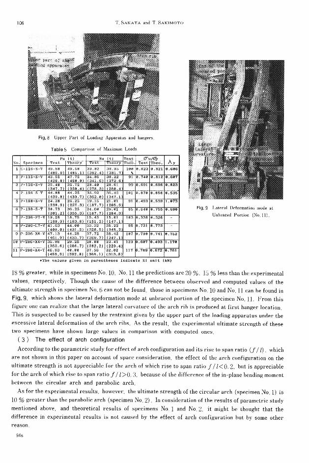
18 % greater, while in specimens No. 10, No. ll the predictions are 20 %. 15 % less than the experimental values, respectively. Though the cause of the difference between observed and computed values of the
ultimate strength in specimen No. 6 can not be found, those in specimens No. 10 and No. 11 can be found in
Fig. 9, which shows the lateral deformation mode at unbraced portion of the specimen No. 11. From this
figure one can realize that the large lateral curvature of the arch rib is produced at first hanger location. This is suspected to be caused by the restraint given by the upper part of the loading apparatus under the
excessive lateral deformation of the arch ribs. As the result, the experimental ultimate strength of these
two specimens have shown large values in comparison with computed ones.
(3) The effect of arch configuration
According to the parametric study for effect of arch configuration and its rise to span ratio (f11), which
are not shown in this paper on account of space consideration, the effect of the arch configuration on the
ultimate strength is not appreciable for the arch of which rise to span ratio f /1<0.2, but is appreciable
for the arch of which rise to span ratio f/1>0.3, because of the difference of the in-plane bending moment
between the circular arch and parabolic arch.
As for the experimental results, however, the ultimate strength of the circular arch (specimen No. 1) is
10 % greater than the parabolic arch (specimen No. 2). In consideration of the results of parametric study mentioned above, and theoretical results of specimens No. I and No. 2, it might be thought that the
difference in experimental results is not caused by the effect of arch configuration but by some other
reason
Fig. 8 Upper Part of Loading Apparatus and hangers.
Table 5 Comparison of Maximum Loads.
1he values given In parentheses indicate SI unit (kN)
Fig. 9 Lateral Deformation mode at
Unbraced Portion (No. 11).
94s

Experimental Study on the Out-of-Plane Buckling Strength of Steel Arches with Open Cross Section 107
(4) Buckling mode of the arch rib The buckling modes of the specimens are shown in Fig. 10, where the maximum lateral displacement is
shown by unit length. In this figure, the solid line and broken line represent the modes obtained from
experiment and from computation, respectively. As shown in Fig. 10, the correspondence betweenmeasured and computed values is fairly good. It is also shown that
the theoretical values can follow the asymmetric shape of the
measured lateral deflection caused by the asymmetric initial
deflection.
In the case of the single arch specimen, the mode of lateral
deflection is similar to the buckling mode of the clamped-clamped
column, but the torsional deformations of arch rib at the portion
near the both ends show the opposite sign to that observed at the
arch crown as shown in Fig. 10 (a) 10). In the case of the specimen of
twin arches having the bracing system, the lateral buckling modes
are classified into two groups. That is, cases No. 7 and 8 show a
similar mode to that of the single arch specimen, and cases No. 9,
10 and 11 show another type of mode where most of the lateral deformations are produced at the unbraced portion.
(5) Effect of the load direction Experimental results for the relationship between the load and
lateral deflection at the crown of single arch rib are shown in
Fig. 11. It can be seen from this figure that the ultimate strength of the arch subjected to the tilting hanger load is quite large comparing
with the case of the vertical load. The reason is that a tilting hanger
produces a restoring lateral force which has stabilizing effect on lateral buckling of the arch as shown in the inset of Fig. 11.
As is clear from what mentioned above, the effect of load
direction is also very significant for the lateral buckling strength of
arch bridges and the effect depends on the degree of lateral
restraint of the loading beam in experiment, while for actual arch
bridges of through-type it depends on the lateral flexural rigidity of
the floor girder system7).
(6) Effect of the type of bracing system Since the St. Venant torsional rigidity of thin-walled member
with open cross section is much smaller than that of a member with
closed cross section, there was a possibility that the contribution
rate of the bracing system type-P which mainly resists torsion of
the arch rib might come close or superior to that of the bracing
system type-L for the arch model with open profile ribs. In order to
examine the effect of bracing system on increase in ultimate
strength, the experimental results of specimen No. 7 (bracing type
P 7) and No. 8 (bracing type L 7) are compared with the theoretical
result of single arch whose cross section is the one of twin arch
ribs. The load versus lateral displacement curves at crown for
these models are shown in Fig. 12. From this figure, the ultimate
strength of specimen No. 7 (P 7) is 1. 4 times and specimen No. 8
(L 7) is 3. 0 times greater than that of single arch rib. That is, the
Fig, 1 0 Modes of Lateral Deformations
of Arch Ribs
(a) Torsional deformation
-Theory
-○-Test
No. 5 P-198-S-V (single)
(b) Lateral Deflection
No. 5 P-198-S-V (single)
No. 7 P-296-P7--V (twin)
No. 9 P-296-X6-V (twin)
No. 10 P-296-X4-V (twin)
Fig. 1 1 Load versus Lateral Deflection
Curves (Single arch).
95s

108 T. SAKATA and T. SAKIMOTO
bracing system which resists the lateral bending of arch ribs (type L) is more effective for increasing the
ultimate strength than that (type P) which resists the torsion of arch ribs, even in the arch system with
open profile ribs. Since type X is more effective system than type L for resisting the lateral bending, it can
be confirmed from Fig. 12 that the type X is the most efficient bracing system. Anyway, it is clear from
what mentioned above that the ultimate strength of twin arches is affected considerably by the type of bracing system.
(7) Effect of the braced length ratio The effect of braced length ratio fi on the ultimate strength of arch can be observed by comparing the
results of the specimen No. 9 (bracing type X 6) with those of the specimen No. 10 (bracing type X 4 V),
because these two specimens are tested under the same condition except the braced length ratio , Q and
inevitable initial lateral crookedness. According to the experimental results (Fig. 12), the ultimate
strength of specimen No. 9 (f3=0.75) is 30 % greater than that of specimen No. 10 (l=0.50). In the case
of bracing type X, when we assume that the arch ribs are connected rigidly by the bracing members, the
moment inertia of cross section of the twin arch ribs about lateral bending at the braced portion can be
determined by Iy=2 Io+2 A (a/2) 2, while at the unbraced portion Iy=2 Io, where Io denotes the moment
inertia of cross section of a single arch rib, a is the distance between twin arch ribs and A is the cross
sectional area of a single arch rib.
Since the lateral bending stiffness of the twin arch ribs at the braced portion is much larger than that at
the unbraced portion, most of the lateral deflection of arch rib are produced by the deformation at the
unbraced portion as shown in Fig. 10. These facts mean that the ultimate strength of the through type arch
bridges having unbraced portion are greatly affected by the slenderness ratio of the unbraced portion of
arch rib, in other words, the effect of the braced length ratio , 9 is quite significant for the ultimate
strength of twin arch models having unbraced portion.
(8) Axial force of lateral bracing members Fig. 13 shows the relation between the load and the axial strain of the diagonal and the transverse
members located at the end panel of laterally braced portion. In this figure, the circles represent
experimental results. The basic feature of the relation is that the axial force of diagonal members increase
almost linearly from the beginning of loading and the linearity gradually disappears as the lateral deflection
increases. The linear increase in the axial compressive force of diagonal members are not produced by the
Fig. 12 Load versus Lateral Deflection Curves
(Twin arches). Fig, 13 Load versus Axial Strain Curves for Bracing
Members (P-296-X 6-V).
T: Transverse Member
D: Diagonal Member
96s

Experimental Study on the Out-of-Plane Buckling Strength of Steel Arches with Open Cross Section 109
lateral deformation of the arch but by the shrinkage of the arch rib. Then, in the higher loading stage, the
component of shear force produced by lateral displacement of arch ribs is added to the axial force of
diagonal members. Since the lateral displacement does not increase proportionally to the load increase,
the linearity gradually disappears as lateral deflection increases. That is, the axial compression force of
the diagonal member No. 2 decreases and that of the diagonal member No. 1 increases nearly at 40 tons
(392 kN) of vertical load as shown in Fig. 13. On the other hand, the axial force of the transverse member is a tensile force, which is produced by the axial force of the diagonal members. It is important to point out
that the axial force of diagonal members produced by the shrinkage of the arch rib is significant for
proportioning diagonal members as well as the axial force caused by the design lateral load, that is, the wind load and the seismic load.
(9) Lateral bending strain The vertical load versus lateral bending strain curves for specimen No. 10 (bracing type X 4 V) are
shown in Fig. 14. The strains are measured at the end of arch rib (section 1), at the end of braced region
(section 2) and at the crown of arch (section 3). It can be seen that, at the final stage of loading, large lateral bending strains are developed at the springing and the end of the braced region of arch rib in
opposite sign each other. The large lateral bending strains correspond to the large lateral curvature of the
arch rib. On the contrary, the strain at the arch crown stays in fairly small value, because the braced
region displaces due to the rigid body motion and does not deform much. These facts correspond to the
results of lateral deflection mode shown in Fig. 10. From these considerations we can have a suggestion
that it is possible to increase the ultimate strength of twin arches having unbraced portion by strengthening
the arch ribs in the unbraced portion.
(10) Evaluation of the ultimate strength Fig. 15 shows the experimental results for buckling strength of arch specimens. In this figure, the
ultimate strength is represented by the non-dimensionalized average normal stress au/cry=Nu/AQ5 (See 3.
(2)). The slenderness parameter of single arch rib, is defined as follows by assuming the arch as a
Fig. 14 Load versus Lateral Bending Strain
Curves (P-296-X 4-V).
Fig. 15 Experimental Results for Buckling
Strength of Model Arches.
Twin Single
-No. 9
□No. 10
□No. 11
□ No. l
□No. 2
△No.3
▲No. 4
○No. 5
○No. 6
Fig. 16 Theoretical Results for Buckling
Strength of Model Arches.
Twin Single
□No. 9
□No●10
□No. 11
◇No. 1□ No. 2
□ No. 3
△No. 4
○No. 5
○No. 6
97s

110 T. SAKATA and T. SAKIMOTO
clamped-clamped straight column of length L,
λ=1-πUyF・Ulry (1)
where 6y is the yield point stress of the steel, E stands for Young's modulus, L denotes the curved length
of the arch rib, ry is the radius of gyration of arch rib cross section with respect to out-of-plane bending.
For the case of tilting load, Ay is reduced by multiplying the additional effective length factor K1=0. 65,
which is determined in the previous study and accounts for the effect of tilting load. The slenderness
parameter Ay for twin arch specimens, which are braced with double diagonals in combination with transverse bars, are obtained from Ref. 7) which proposes a method to determine the slenderness
parameter for arch bridges having closed profile cross section. That is,
λy=1π σ=E・K2KzK=rβ1 (2)
where
Ke: effective length factor for end condition. Ke=0.5 for laterally clamped end, Ke=1.0 for laterally hinged end.
K1 : effective length factor counts for the effect of load direction.
K1=0. 65 for tilting load (No. 11), K1=1.0 for vertical load (No. 9, No. 10)
Ka: effective length factor related to the braced length ratio /.
K, =1-9+2 ry (0. 5+0.94/)/(aKe)9K=0. 376 for /9=0. 75 (No. 9), K=0. 584 for /9=0. 50 (No. 10, No. 11)
The derivation of these effective length factor are shown in Ref. 7). The solid line in the figure indicates
the standard column strength curve specified in the Japanese Specifications for Highway Bridges.
Since the lateral deformation of the arch is characterized by the interaction between the lateral
deflection and the torsional deformation, it has been expected that the buckling strength of arch member having open cross section is much smaller than the buckling strength of imaginary straight column of which
slenderness parameter is given by Eq. (1). But, as can be seen from Fig. 15, the experimental results for
buckling strength of single arch rib except No. 6 have good correspondence to the standard column strength
curve. The experimental results of twin arches having X type of bracing system are a little higher than the
strength curve. On the other hand, theoretical results coincide comparatively well with the standard
column strength curve as shown in Fig. 16. Judging from these results, it is suggested that the ultimate
strength of a single arch member with open cross section subjected to uniformly distributed in-plane load
can be approximately predicted by the buckling strength of a clamped-clamped column of length L with the identical cross section.
It is also shown that the ultimate strength of the twin arches specimens having X type of bracing system,
can be estimated approximately by the standard column strength curve utilizing the equivalent slenderness
parameter for arch bridges proposed in Ref. 7). Important point is that no regard is paid for the torsional stiffness of the arch system in evaluating the lateral torsional buckling strength. In other words the lateral
buckling strength of these arch models can be predicted approximately as flexural buckling of an equivalent
straight column.
4. CONCLUSIONS
The following conclusions can be drawn from this study
(1 ) The ultimate strength of a single arch member with open cross section subjected to uniformly distributed in-plane load can be approximately predicted by the buckling strength of a clamped-clamped
column of length L with the identical cross-section. But further theoretical investigation may be necessary
to make clear the influence of torsional rigidity on the inelastic lateral buckling strength of arch member
with open cross section including with different profile other than H sections.
98s

Experimental Study on the Out-of-Plane Buckling Strength of Steel Arches with Open Cross Section 111
(2) The ultimate strength of arch models subjected to the tilting hanger load is quite large comparing with the case of the vertical load. The effect of load direction is also very significant for the lateral
buckling strength of arch bridges. This stabilizing effect can be well evaluated by the proposed effective
length factor K1=0.65 to predict the strength by a column strength formula.
(3) The ultimate strength of arch models with twin ribs is affected considerably by the type of bracing system. That is, the bracing system which resists the lateral bending of arch ribs is more effective for
increasing the ultimate strength than that which resists the torsion of arch ribs.
(4) Since the ultimate strength of the arch models having unbraced portion is greatly affected by the slenderness ratio of the unbraced portion of arch rib, the effect of braced length ratio is also very
significant for the ultimate strength of twin arches having unbraced portion.
(5) The axial force of diagonal members induced by the axial shrinkage of the arch rib is quite significant for proportioning diagonal members as well as the axial force caused by the usual design lateral
load.
(6) The large lateral bending occurs in the end portions of arch ribs where no lateral bracing is located, while the lateral bending moment of the arch rib in the braced portion is fairly small. It is possible
to increase the ultimate strength of twin arches having unbraced portion by strengthening the arch ribs in the unbraced portion.
(7) It is shown that the ultimate strength of single rib arches and twin arches with X-type bracing system can be predicted fairly well by the formula for arches with closed cross section proposed by the
writers in Ref. 7).
(8) Since the theoretical predictions show good correspondence with the experimental results, the validity of the theory is confirmed. Now, it is ready to carry out parametric studies for the ultimate
strength of arch structures with open cross section by the theoretical method presented in Ref. 9).
ACKNOWLEDGMENTS
This study was carried out in three years from 1986 to 1988. The writers express their appreciation and
gratitude to Messrs. Kazuomi Koga, Loh Kok Choon, Toshiyuki Kobori, Giichirou Uemura and Kenji Kugimiya for their valuable help in the experiments. The writers are specially indebted to Mr. Yasuo
Miyazaki, technician of the department, for his assistance in all phases of the experiments. Part of this
investigation was supported by the Grant-in-aid for Scientific Research from the Ministry of Education, of which supervisor is Dr. Yuhshi Fukumoto, Prof. of Osaka university.
REFERENCES
1) Kee, C. F.: Lateral Inelastic Buckling of Tied Arches, Proc, of ASCE. Vol. 87, No. ST 1, pp. 23-39, 1961.
2) Komatsu, S. and Sakimoto, T.: Ultimate Load Carrying Capacity of Steel Arches, Proc. of ASCE, Vol. 103, No. ST 12,
pp. 2323-2336. 1977.
3) Kuranishi, S. and Yabuki, T.: Effect of Lateral Bracing Rigidities on the Ultimate Strength of Steel Arch Bridges, Proc. of
JSCE, No. 305, pp. 47-58, 1981 (in Japanese).
4) Sakimoto, T. and Komatsu, S.: Ultimate Strength of Arches with Bracing Systems, Proc. of ASCE, Vol. 108, No. ST 5,
pp. 1064-1076, 1982.
5) Sakimoto, T. and Komatsu, S. Ultimate Strength Formula for Steel Arches, Proc. of ASCE, Vol. 109, No. ST 3,
pp. 613-627, 1983.
6) Sakimoto, T, and Komatsu, S.: Ultimate Strength Formula for Central-Arch-Girder-Bridges, Proc. of JSCE, No. 333,
pp. 183-186, 1983.
7) Sakimoto, T., Tsuruta, E. and Sakata, T.: Elasto-plastic Out-of-plane Buckling Strength of Through Type and Half-through
Type Arch Bridges, Journal of Structural Eng., Vol. 34 A, pp. 243-254, 1987 (in Japanese).
8) Sakimoto, T., Yamao, T. and Komatsu, S.: Experimental Study on Ultimate Strength of Steel Arches, Proc. of JSCE,
No. 286, pp. 139-149, 1979.
9) Sakimoto, T., Yamao, T., Kikuchi, R. and Sakata, T.: Nonlinear Analysis of Thin-walled Frames and Members with
99s
112 T. SAKATA and T. SAKIMOTO
Arbitrary Open Cross-Section, Proc. of JSCE Structural Eng. /Earthquake Eng., Vol. 2, No. 2, pp. 139-147. Oct. 1985.
10) Fukasawa, Y.: Buckling of Circular Arches by Lateral Flexure and Torsional under Axial Thrust, Transaction of JSCE,
No. 96, pp. 29-47, 1963 (in Japanese).
11) Japan Road Association : Specifications for Highway Bridges, Feb. 1980.
(Received June 28 1989)
100s