Embed Size (px)
Citation preview
EXPERIMENTAL STUDY OF THREE RETROFITTING TECHNIQUES
FOR TYPICAL SCHOOL BUILDINGS IN PERU
Miguel DIAZ1, Carlos ZAVALA2, Luis LAVADO3, Jorge GALLARDO4, Roy REYNA5
ABSTRACT
Between decade of 1980 and 1990, several typical school buildings were constructed; their design used
parameters based on seismic zones and soil conditions, considering the Peruvian earthquake resistant standard of
1977, which had quite limited thresholds. These school buildings, named 780-module, are composed by RC
frames and confined masonry walls, which suffered short-column effect during severe last quakes in Peru. Later,
its design was improved according the following version of the seismic code; nevertheless, some constructers
kept building schools with their own adaption of the original design with no qualified revision. Nowadays, there
are thousands school buildings with non-adequate earthquake resistant structures. In that sense, retrofitting
techniques of quick intervention process to take advantage of vacation break are needed.
This article present an experimental study of three different seismic retrofitting techniques in order to avoid
mainly the short-column effect of 780-modules. Retrofitting techniques are ACMAC (steel bracing of RC
frames), MARM (confined masonry walls strengthening with cement-sand mortar and wire mesh) and IMACA
(RC frames strengthening with coupled RC walls). Thus, seven full-scale cyclic loading tests were conducted in
representative frames of 780-module. Specimens consisted of reinforced concrete frames of one story and two
bays. Experimental tests showed that essentially specimens retrofitted with ACMAC technique performed better
seismic behavior than those retrofitted with MARM and IMACA techniques.
Keywords: Retrofitting; Cyclic loading test; School buildings; concentric steel frame
1. INTRODUCTION
Current earthquake resistant standards attempts that school buildings are high seismic capacity
structures, because they provide not only shelter to students and the rest of affected people but also
motivation to families to enroll their children in school. Current Peruvian earthquake resistant
standards (SENCICO, NTE E030) provides considerations to reach fully operational performance
level in school buildings. Nevertheless, several school buildings were constructed between decade of
1980 and 1990, using designs developed under typical parameters, based on seismic zones and soil
conditions, considering earthquake resistant standard of 1977, which provided quite limited thresholds.
These school buildings, named 780-module, are composed by RC frames and confined masonry walls
(SENCICO, NTE E030). School buildings suffered short-column effect during severe last quakes in
Peru, as shown in Figure 1 (over 90 school buildings were damaged). School buildings based on 780-
module were very affected; in consequence, its design was improved according the following version
of the seismic code. Notwithstanding the new version of 780-module, some constructers kept
constructing schools buildings with their own adaption of the original design (oldest version) with no
qualified revision. Nowadays, there are thousands schools with non-adequate earthquake resistant
structures.
1Associate Professor of Faculty of Civil Engineering, UNI, Lima, Peru, [email protected] 2Professor of Faculty of Civil Engineering, UNI, Lima, Peru, [email protected] 3Assistant Professor of Faculty of Civil Engineering, UNI, Lima, Peru, [email protected] 4Associate Professor of Faculty of Civil Engineering, UNI, Lima, Peru, [email protected] 5Assistant Professor of Faculty of Civil Engineering, UNI, Lima, Peru, [email protected]

2
Figure 1. Fermin del Castillo School after Nazca earthquake in 1996, Mw7.7. Zavala, 1996
On the other hand, Lima city concentrates over 25% of population of Peru; and it is exposed to a
seismic gap according to some studies conducted under SATREPS Project (cooperation from Japanese
Government to the National University of Engineering of Lima, Peru between 2010 and 2015). These
studies showed that a severe earthquake (Mw8.6~8.9) may occur in Lima City (Pulido et al., 2011)
and it can result in harmful consequences. In that sense, retrofitting techniques of quick intervention
process, to take advantage of vacation break, are needed to improve their seismic capacity.
A project support by the World Bank to develop a proposed update to incorporate incremental
retrofitting to school infrastructure type 780-module built before 1997 started a few years ago. One of
the goal of this project was provided three retrofitting techniques in order to avoid mainly the short-
column effect of 780-modules. Thus, several retrofitting techniques were evaluated, and then three
techniques were selected to be experimentally studied. Retrofitting techniques are ACMAC (steel
bracing of RC frames), MARM (confined masonry walls strengthening with cement-sand mortar and
wire mesh) and IMACA (RC frames strengthening with coupled RC walls).
1.1 Objectives
The objective of this investigation is to know the seismic behavior by lateral cycling loading tests and
compare the experimental results of three retrofitting technique for improving the seismic capacity of
typical school buildings in Peru, called 780-module.
1.2 Target school building
The target school building is the first version of 780-module; which was design with Peruvian
earthquake resistant standard of 1977. This module consists of two stories and three rooms per story,
as shown in Figure 2. This structure is composed by RC frames in longitudinal direction and confined
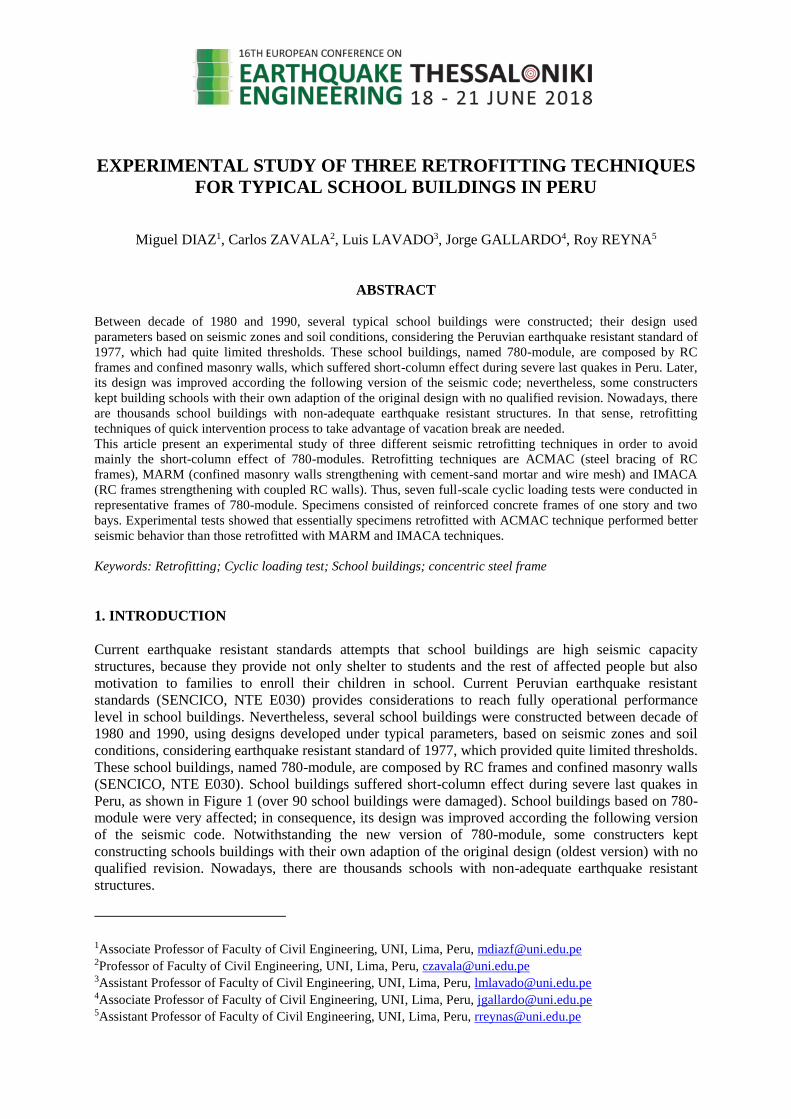
masonry walls in the transversal direction, as illustrated in Figure 3. Dimensions of room is 7.80 m by
side; that’s why, it was named 780-module. It is important to mention that longitudinal direction
suffered severe damages, while transversal direction was slightly damaged due to large earthquakes.
Figure 2. School building based on 780-module
3
Figure 3. Typical floor of 780-module
2. PROPOSED RETROFITTING TECHNIQUE
In order to select the most suitable retrofitting technique, several retrofitting techniques were
evaluated. Then, three retrofitting techniques were experimentally studied. These retrofitting
techniques are ACMAC (steel bracing of RC frames), MARM (confined masonry walls strengthening
with cement-sand mortar and wire mesh) and IMACA (RC frames strengthening with coupled RC
walls). These seismic retrofitting techniques are supposed to be implemented in certain number of
frames in the target school building according to the seismic demand that is required, because their
implementation depends on the incremental retrofitting program. Their seismic performance must
satisfy the performance objectives establish in the earthquake resistant standards.
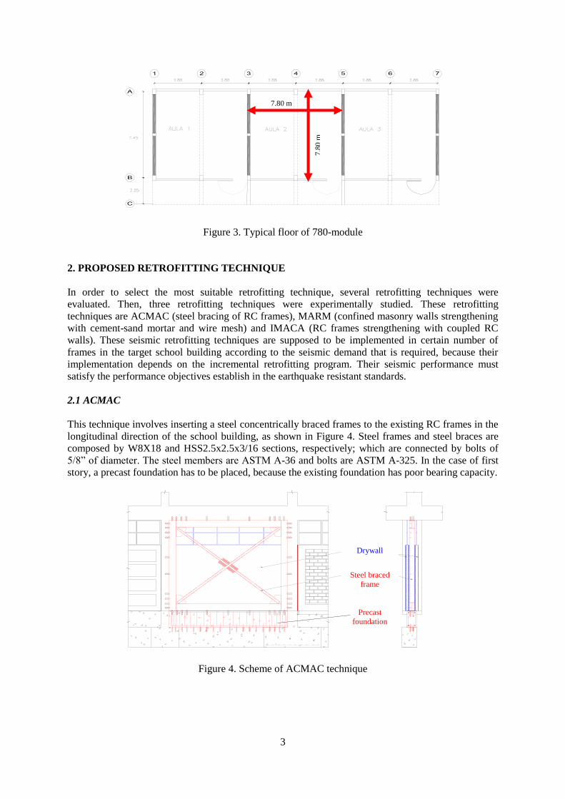
2.1 ACMAC
This technique involves inserting a steel concentrically braced frames to the existing RC frames in the
longitudinal direction of the school building, as shown in Figure 4. Steel frames and steel braces are
composed by W8X18 and HSS2.5x2.5x3/16 sections, respectively; which are connected by bolts of
5/8” of diameter. The steel members are ASTM A-36 and bolts are ASTM A-325. In the case of first
story, a precast foundation has to be placed, because the existing foundation has poor bearing capacity.
Figure 4. Scheme of ACMAC technique
Steel braced
frame
Drywall
Precast
foundation
7.8
0 m
7.80 m
4
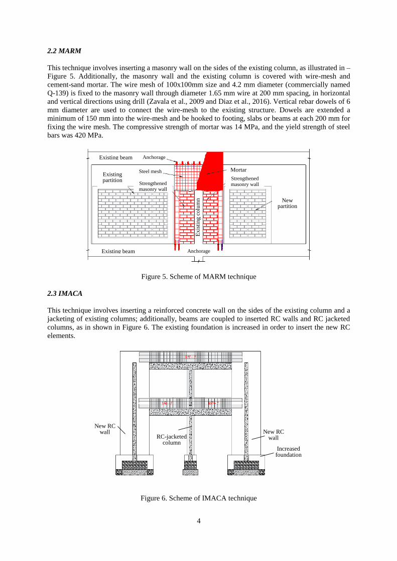
2.2 MARM
This technique involves inserting a masonry wall on the sides of the existing column, as illustrated in –
Figure 5. Additionally, the masonry wall and the existing column is covered with wire-mesh and
cement-sand mortar. The wire mesh of 100x100mm size and 4.2 mm diameter (commercially named
Q-139) is fixed to the masonry wall through diameter 1.65 mm wire at 200 mm spacing, in horizontal
and vertical directions using drill (Zavala et al., 2009 and Diaz et al., 2016). Vertical rebar dowels of 6
mm diameter are used to connect the wire-mesh to the existing structure. Dowels are extended a
minimum of 150 mm into the wire-mesh and be hooked to footing, slabs or beams at each 200 mm for
fixing the wire mesh. The compressive strength of mortar was 14 MPa, and the yield strength of steel
bars was 420 MPa.
Figure 5. Scheme of MARM technique
2.3 IMACA
This technique involves inserting a reinforced concrete wall on the sides of the existing column and a
jacketing of existing columns; additionally, beams are coupled to inserted RC walls and RC jacketed
columns, as in shown in Figure 6. The existing foundation is increased in order to insert the new RC
elements.
Figure 6. Scheme of IMACA technique
Existing beam
Existing partition
Existing beam
New partition
Ex
isti
ng
co
lum
n
Strengthened masonry wall
Mortar
Strengthened masonry wall
Steel mesh
Anchorage
Anchorage
RC-jacketed column
New RC wall
New RC wall
Increased foundation
5
3. CYCLIC LOADING TEST
In order to verify the performance of these retrofitting techniques, representative frames of 780-
module were tested under cyclic static horizontal loading with constant axial load.
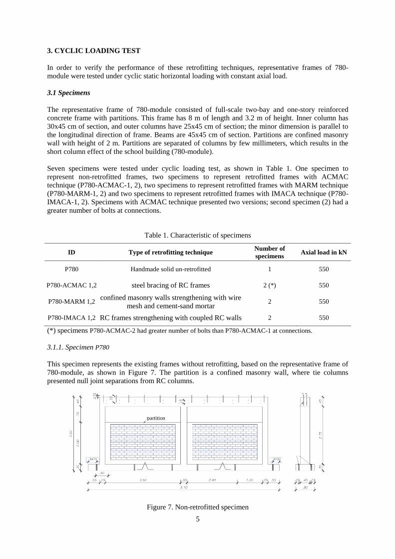
3.1 Specimens
The representative frame of 780-module consisted of full-scale two-bay and one-story reinforced
concrete frame with partitions. This frame has 8 m of length and 3.2 m of height. Inner column has
30x45 cm of section, and outer columns have 25x45 cm of section; the minor dimension is parallel to
the longitudinal direction of frame. Beams are 45x45 cm of section. Partitions are confined masonry
wall with height of 2 m. Partitions are separated of columns by few millimeters, which results in the
short column effect of the school building (780-module).
Seven specimens were tested under cyclic loading test, as shown in Table 1. One specimen to
represent non-retrofitted frames, two specimens to represent retrofitted frames with ACMAC
technique (P780-ACMAC-1, 2), two specimens to represent retrofitted frames with MARM technique
(P780-MARM-1, 2) and two specimens to represent retrofitted frames with IMACA technique (P780-
IMACA-1, 2). Specimens with ACMAC technique presented two versions; second specimen (2) had a
greater number of bolts at connections.
Table 1. Characteristic of specimens
ID Type of retrofitting technique Number of
specimens Axial load in kN
P780 Handmade solid un-retrofitted 1 550
P780-ACMAC 1,2 steel bracing of RC frames 2 (*) 550
P780-MARM 1,2 confined masonry walls strengthening with wire
mesh and cement-sand mortar 2 550
P780-IMACA 1,2 RC frames strengthening with coupled RC walls 2 550
(*) specimens P780-ACMAC-2 had greater number of bolts than P780-ACMAC-1 at connections.
3.1.1. Specimen P780
This specimen represents the existing frames without retrofitting, based on the representative frame of
780-module, as shown in Figure 7. The partition is a confined masonry wall, where tie columns
presented null joint separations from RC columns.
Figure 7. Non-retrofitted specimen
partition
6
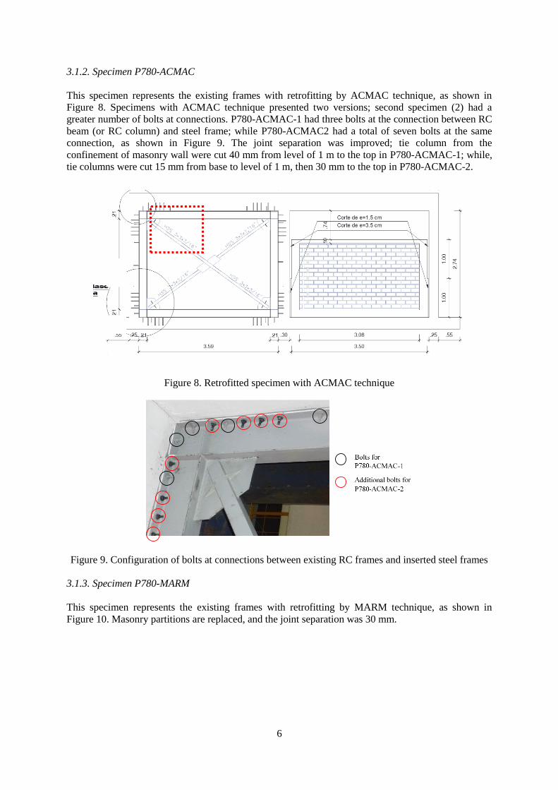
3.1.2. Specimen P780-ACMAC
This specimen represents the existing frames with retrofitting by ACMAC technique, as shown in
Figure 8. Specimens with ACMAC technique presented two versions; second specimen (2) had a
greater number of bolts at connections. P780-ACMAC-1 had three bolts at the connection between RC
beam (or RC column) and steel frame; while P780-ACMAC2 had a total of seven bolts at the same
connection, as shown in Figure 9. The joint separation was improved; tie column from the
confinement of masonry wall were cut 40 mm from level of 1 m to the top in P780-ACMAC-1; while,
tie columns were cut 15 mm from base to level of 1 m, then 30 mm to the top in P780-ACMAC-2.
Figure 8. Retrofitted specimen with ACMAC technique
Figure 9. Configuration of bolts at connections between existing RC frames and inserted steel frames
3.1.3. Specimen P780-MARM
This specimen represents the existing frames with retrofitting by MARM technique, as shown in
Figure 10. Masonry partitions are replaced, and the joint separation was 30 mm.

7
Figure 10. Retrofitted specimen with MARM technique.
3.1.4. Specimen P780-IMACA
This specimen represents the existing frames with retrofitting by IMACA technique, as shown in
Figure 11. Masonry partitions are replaced, and the joint separation was 40 mm.
Figure 11. Retrofitted specimen with IMACA technique.
3.2 Test setup
The test setup consisted of four hydraulic static jacks, with the 500 kN loading capacity of each jack
and a stroke of +/- 250 mm. Two jacks applied simultaneously lateral cyclic loading to simulate the
seismic load, while other two jacks applied a constant vertical loading to simulate the gravity load due
to upper floors. The axial load remained constant during test at 550 kN. The displacement protocol
used in tests is shown in Figure 12. The target displacement is repeated; thus, two cycles with the same
deformation are obtained.
Figure 12. Lateral displacement protocol for lateral cyclic loading tests
8
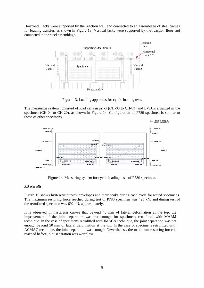
Horizontal jacks were supported by the reaction wall and connected to an assemblage of steel frames
for loading transfer, as shown in Figure 13. Vertical jacks were supported by the reaction floor and
connected to the steel assemblage.
Figure 13. Loading apparatus for cyclic loading tests
The measuring system consisted of load cells in jacks (CH-00 to CH-03) and LVDTs arranged in the
specimen (CH-04 to CH-20), as shown in Figure 14. Configuration of P780 specimen is similar to
those of other specimens.
Figure 14. Measuring system for cyclic loading tests of P780 specimen.
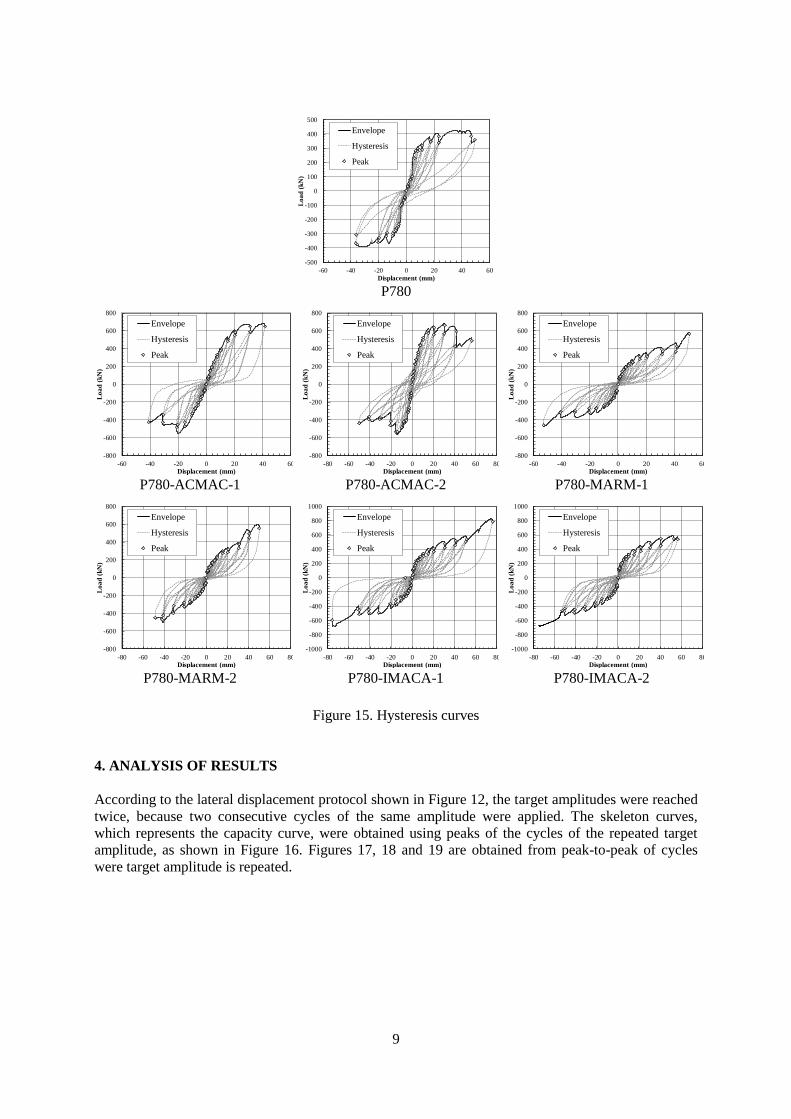
3.3 Results
Figure 15 shows hysteretic curves, envelopes and their peaks during each cycle for tested specimens.
The maximum restoring force reached during test of P780 specimen was 425 kN, and during test of
the retrofitted specimen was 692 kN, approximately.
It is observed in hysteresis curves that beyond 40 mm of lateral deformation at the top, the
improvement of the joint separation was not enough for specimens retrofitted with MARM
technique. In the case of specimens retrofitted with IMACA technique, the joint separation was not
enough beyond 50 mm of lateral deformation at the top. In the case of specimens retrofitted with
ACMAC technique, the joint separation was enough. Nevertheless, the maximum restoring force is
reached before joint separation was worthless.
.60
.60
Supporting Steel frames
Vertical
Jack 1 Vertical
Jack 2
Reaction slab
Reaction
wall
Horizontal
Jack 1,2
Specimen
9
P780
P780-ACMAC-1
P780-ACMAC-2
P780-MARM-1
P780-MARM-2
P780-IMACA-1
P780-IMACA-2
Figure 15. Hysteresis curves
4. ANALYSIS OF RESULTS
According to the lateral displacement protocol shown in Figure 12, the target amplitudes were reached
twice, because two consecutive cycles of the same amplitude were applied. The skeleton curves,
which represents the capacity curve, were obtained using peaks of the cycles of the repeated target
amplitude, as shown in Figure 16. Figures 17, 18 and 19 are obtained from peak-to-peak of cycles
were target amplitude is repeated.
-500
-400
-300
-200
-100
0
100
200
300
400
500
-60 -40 -20 0 20 40 60
Lo
ad
(kN
)
Displacement (mm)
Envelope
Hysteresis
Peak
-800
-600
-400
-200
0
200
400
600
800
-60 -40 -20 0 20 40 60
Lo
ad
(kN
)
Displacement (mm)
Envelope
Hysteresis
Peak
-800
-600
-400
-200
0
200
400
600
800
-80 -60 -40 -20 0 20 40 60 80
Lo
ad
(kN
)
Displacement (mm)
Envelope
Hysteresis
Peak
-800
-600
-400
-200
0
200
400
600
800
-60 -40 -20 0 20 40 60
Lo
ad
(kN
)
Displacement (mm)
Envelope
Hysteresis
Peak
-800
-600
-400
-200
0
200
400
600
800
-80 -60 -40 -20 0 20 40 60 80
Lo
ad
(kN
)
Displacement (mm)
Envelope
Hysteresis
Peak
-1000
-800
-600
-400
-200
0
200
400
600
800
1000
-80 -60 -40 -20 0 20 40 60 80
Lo
ad
(kN
)
Displacement (mm)
Envelope
Hysteresis
Peak
-1000
-800
-600
-400
-200
0
200
400
600
800
1000
-80 -60 -40 -20 0 20 40 60 80
Lo
ad
(kN
)
Displacement (mm)
Envelope
Hysteresis
Peak
10
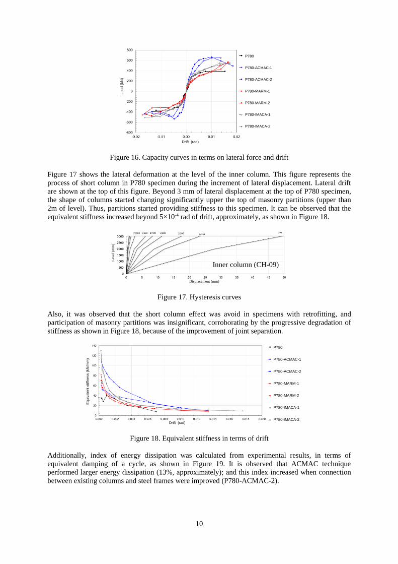
Figure 16. Capacity curves in terms on lateral force and drift
Figure 17 shows the lateral deformation at the level of the inner column. This figure represents the
process of short column in P780 specimen during the increment of lateral displacement. Lateral drift
are shown at the top of this figure. Beyond 3 mm of lateral displacement at the top of P780 specimen,
the shape of columns started changing significantly upper the top of masonry partitions (upper than
2m of level). Thus, partitions started providing stiffness to this specimen. It can be observed that the
equivalent stiffness increased beyond 5×10⁻⁴ rad of drift, approximately, as shown in Figure 18.
Figure 17. Hysteresis curves
Also, it was observed that the short column effect was avoid in specimens with retrofitting, and
participation of masonry partitions was insignificant, corroborating by the progressive degradation of
stiffness as shown in Figure 18, because of the improvement of joint separation.
Figure 18. Equivalent stiffness in terms of drift
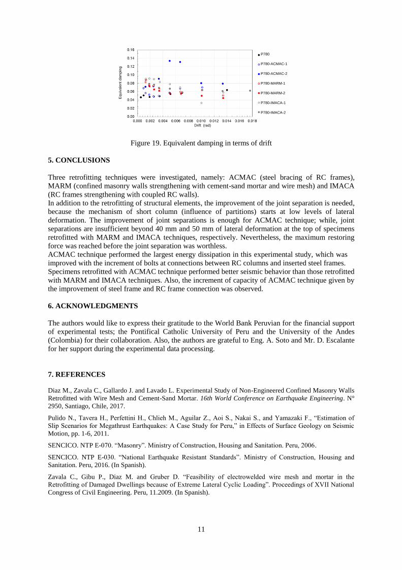
Additionally, index of energy dissipation was calculated from experimental results, in terms of
equivalent damping of a cycle, as shown in Figure 19. It is observed that ACMAC technique
performed larger energy dissipation (13%, approximately); and this index increased when connection
between existing columns and steel frames were improved (P780-ACMAC-2).
P780
P780-ACMAC-1
P780-ACMAC-2
P780-MARM-1
P780-MARM-2
P780-IMACA-1
P780-IMACA-2
Drift (rad)
Loa
d (
kN
)
Displacement (mm)
Lev
el (
mm
)
P780
P780-ACMAC-1
P780-ACMAC-2
P780-MARM-1
P780-MARM-2
P780-IMACA-1
P780-IMACA-2
Drift (rad)
Equiv
ale
nt stiff
ness (
kN
/mm
)
P780
P780-ACMAC-1
P780-ACMAC-2
P780-MARM-1
P780-MARM-2
P780-IMACA-1
P780-IMACA-2
Drift (rad)
Loa
d (
kN
)
Inner column (CH-09)
11
Figure 19. Equivalent damping in terms of drift
5. CONCLUSIONS
Three retrofitting techniques were investigated, namely: ACMAC (steel bracing of RC frames),
MARM (confined masonry walls strengthening with cement-sand mortar and wire mesh) and IMACA
(RC frames strengthening with coupled RC walls).
In addition to the retrofitting of structural elements, the improvement of the joint separation is needed,
because the mechanism of short column (influence of partitions) starts at low levels of lateral
deformation. The improvement of joint separations is enough for ACMAC technique; while, joint
separations are insufficient beyond 40 mm and 50 mm of lateral deformation at the top of specimens
retrofitted with MARM and IMACA techniques, respectively. Nevertheless, the maximum restoring
force was reached before the joint separation was worthless.
ACMAC technique performed the largest energy dissipation in this experimental study, which was
improved with the increment of bolts at connections between RC columns and inserted steel frames.
Specimens retrofitted with ACMAC technique performed better seismic behavior than those retrofitted
with MARM and IMACA techniques. Also, the increment of capacity of ACMAC technique given by
the improvement of steel frame and RC frame connection was observed.
6. ACKNOWLEDGMENTS
The authors would like to express their gratitude to the World Bank Peruvian for the financial support
of experimental tests; the Pontifical Catholic University of Peru and the University of the Andes
(Colombia) for their collaboration. Also, the authors are grateful to Eng. A. Soto and Mr. D. Escalante
for her support during the experimental data processing.
7. REFERENCES
Diaz M., Zavala C., Gallardo J. and Lavado L. Experimental Study of Non-Engineered Confined Masonry Walls
Retrofitted with Wire Mesh and Cement-Sand Mortar. 16th World Conference on Earthquake Engineering. N°
2950, Santiago, Chile, 2017.
Pulido N., Tavera H., Perfettini H., Chlieh M., Aguilar Z., Aoi S., Nakai S., and Yamazaki F., “Estimation of
Slip Scenarios for Megathrust Earthquakes: A Case Study for Peru,” in Effects of Surface Geology on Seismic
Motion, pp. 1-6, 2011.
SENCICO. NTP E-070. “Masonry”. Ministry of Construction, Housing and Sanitation. Peru, 2006.
SENCICO. NTP E-030. “National Earthquake Resistant Standards”. Ministry of Construction, Housing and
Sanitation. Peru, 2016. (In Spanish).
Zavala C., Gibu P., Diaz M. and Gruber D. “Feasibility of electrowelded wire mesh and mortar in the
Retrofitting of Damaged Dwellings because of Extreme Lateral Cyclic Loading”. Proceedings of XVII National
Congress of Civil Engineering. Peru, 11.2009. (In Spanish).
Equiv
ale
nt
dam
pin
g
Drift (rad)
P780
P780-ACMAC-1
P780-ACMAC-2
P780-MARM-1
P780-MARM-2
P780-IMACA-1
P780-IMACA-2
12
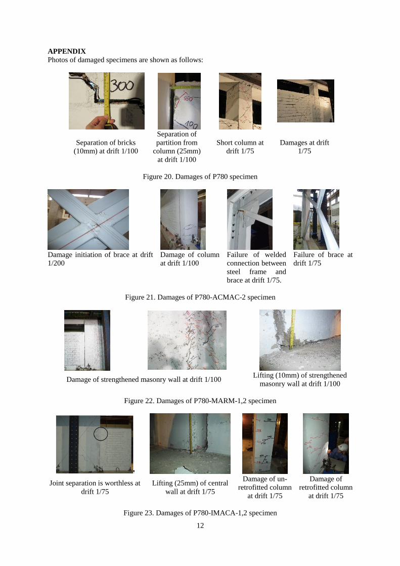
APPENDIX
Photos of damaged specimens are shown as follows:
Separation of bricks
(10mm) at drift 1/100
Separation of
partition from
column (25mm)
at drift 1/100
Short column at
drift 1/75
Damages at drift
1/75
Figure 20. Damages of P780 specimen
Damage initiation of brace at drift
1/200
Damage of column
at drift 1/100
Failure of welded
connection between
steel frame and
brace at drift 1/75.
Failure of brace at
drift 1/75
Figure 21. Damages of P780-ACMAC-2 specimen
Damage of strengthened masonry wall at drift 1/100 Lifting (10mm) of strengthened
masonry wall at drift 1/100
Figure 22. Damages of P780-MARM-1,2 specimen
Joint separation is worthless at
drift 1/75
Lifting (25mm) of central
wall at drift 1/75
Damage of un-
retrofitted column
at drift 1/75
Damage of
retrofitted column
at drift 1/75
Figure 23. Damages of P780-IMACA-1,2 specimen