Embed Size (px)
Citation preview
1
EXPERIMENTAL STUDIES ON IMPROVEMENT OF COP OF WINDOW AIR
CONDITIONING UNIT
Sheik Ismail THARVES MOHIDEEN a and Nagachari NETHAJI
b*
aDepartment of Mechanical Engineering, Institute of Road and Transport Technology,
Erode, India. bDepartment of Mechanical Engineering, DDCSM Polytechnic College, Palacode, India.
This paper presents the performance analysis of a window air
conditioner unit incorporated with Wick less Loop Heat Pipes(WLHP).The WLHPs are located on the evaporator side of the air conditioning unit. The
working medium for the WLHPs is R134a refrigerant gas, an alternate
refrigerant. The supply and return humidity of room air, the heat removal rat
and, the COP (Coefficient of Performance) of the unit are analyzed for various ambient and room temperatures before and after incorporation of WLHPs. The
performance curves are drawn by comparing the power consumption and
humidity collection rates for various room and ambient temperatures. The results show that the COP of the unit is improved by 18% to 20% after
incorporation of WLHPs due to pre cooling of return air by WLHPs, which
reduces the thermal load on compressor. Similarly the energy consumption is reduced by 20% to 25% due to higher thermostat setting and the humidity
collection is improved by 35% due to pre cooling effect of WLHPs. The results
are tabulated and conclusion drawn is presented based on the performance.
Key words: wick less loop heat pipes (WLHP), COP, pre cooling, reheating, return air, supply air, DBT (Dry Bulb Temperature)
1. Introduction
The vapor-compression refrigeration system uses a circulating liquid refrigerant as the working
medium which absorbs and removes the heat from the space to be cooled and subsequently rejects that
heat to ambient. The performance of VCR (Vapor compression Refrigeration) system is measured as
COP. When COP is higher, for a given work input the system extracts more heat and hence it is more
efficient. Several studies on improvement of COP and hence energy conservation in HVAC (Heating,
Ventilating and Air Conditioning) system are reported in literature. In this study, with a view to improve
COP, WLHPs are incorporated in a small capacity window air conditioning system to experimentally
validate it.
The Wick less Loop Heat Pipe (WLHP) is a device that allows transfer of very substantial
quantities of heat through small surface areas over long distances, with small temperature differences and
with no external pumping power. For instance, a heat pipe can transfer 10 times the heat of pure rod with
a 100°C temperature difference (Holman, J.P., 1981. Heat Transfer, fifth ed. McGraw-Hill, Auckland).
____________________
* Corresponding Author. Tel: +919443207556
Email address: [email protected]

2
The WLHP is usually made up of high thermal conductivity materials like copper, aluminum,
brass depending upon the compatibility of working medium and the temperature range of application. A
typical WLHP is shown in the fig.1. Condenser section is larger in the dimension compared to evaporator
for faster heat rejection. Similarly the vapor loop diameter is more than that of liquid loop for easy flow
lighter vapor than the denser liquid working medium. The vapor which flows through the vapor loop due
to thermosyphon effect reach the condenser section of the WLHP, where it rejects the heat and become
Fig.1- Wick less Loop Heat Pipe
saturated liquid at the same pressure and temperature and flows down to the evaporator section through
the liquid loop. Wick less loop heat pipes are designed without wicks, which offer less resistance to flow
unlike in the conventional heat pipes with wicks.
2. Literature review
Several research works have been reported on incorporation of Heat Pipe Heat Exchangers
(HPHX) in HVAC systems to reduce energy consumption, to control humidity and to improve indoor air
quality. Xiao Ping Wu et al. [1] investigated the application of a HPHX to control humidity in air-
conditioning system. They have experimentally investigated the incorporation of HPHX to pre-cool the
return air and reheat the supply air in the normal air-conditioning system to save the precious reheat
energy and also to maintain the required levels of RH. They concluded that with the incorporation of the
above HPEX the cooling capacity of the system is increased by 20 to 32.7% and the RH level maintained
below 70%. Etheridge et al.[2] have conducted a research on PCM/heat pipe cooling system for reducing
air conditioning in buildings. They report that the objective of their research is to retrofit the existing A/C
units in the buildings with above cooling system on commercial scale and to reduce the carbon emission
to save the environment.
Mostafa A. Abd El-Baky et al. [3] carried out an experimental study on HPHX for heat recovery
in air-conditioning. They have reported the application of HPHX for pre-cooling the incoming fresh air in
Vap
or
loop
Evaporator section
Liq
uid
loo
p
Condenser section

3
a HVAC system. Yau [4] carried out an experimental thermal performance study of an inclined HPHX
operating in high humid tropical HVAC systems. He reports that the experimental results suggest that the
influence of condensate formation on the fins of the inclined HPHX was negligible. Hussam Jouhara et al.
[5] conducted an experimental investigation on wrap around loop HPHX, used in energy efficient air
handling units. Their findings show that pre-cooling and dehumidifying functions of HPHX in hot and
humid climates are major contributors to reduce the running costs of the HVAC system.
Suprirattanakul et al. [6] carried out an experimental analysis on application of a closed-loop
oscillating heat pipes with check valves for performance enhancement in air-conditioning system. The
results have shown that the cooling capacity of the test A/C unit had increased by 3.6%, the COP by
14.9% and the Energy Efficiency Ratio (EER) by 17.6%. Ahmadzadehtalatapeh et al. [7] carried out an
experimental study and prediction on energy conservation options of the heat pipe heat exchangers
(HPHX) in air conditioning chamber. Based on the performance characteristics and the empirical
equations, the energy conservation potential of the HPHX for the years of 2000, 2020, and 2050 for Kuala
Lampur were predicted. Hussam Jouhra et al. [8] carried out an investigation on thermal performance
characteristics of a wrap around loop heat pipe charged with R134a refrigerant. They reported an overall
thermal resistance of as low as .048Cw-1
and the same is decreasing with increasing in power input due to
boiling heat transfer characteristics.
Yau et al. [9] reported that the enhanced return of condensate in the Rotating Heat Pipes (RHP)
due to centrifugal force results in high heat transfer rate. A comparison of heat transfer characteristics of
working fluids R134a, R22 and R410a was reported using the RHP with various radial displacements.
Wan et al. [10] carried out a study on the effect of heat pipe air handling coil on energy consumption in
central air-conditioning system. They reported that for a typical 20-26ºC, 50% RH indoor condition, the
rate of energy saving (RES) for the heat pipe equipped air-conditioning is 23.5 to 25.7%. Yau [11] carried
out a theoretical investigation on potential of HPHX on coolness recovery in tropical buildings.
Yau [12] carried out a full year energy consumption model simulation on a double HPHX system
for reducing energy consumption of treating ventilation air in an operating theatre. His report consists of a
case study on energy consumption of an operation theatre in Kuala Lampur, Malasiya. Alklaibi[13]
carried out a theoretical investigations on evaluating the possible configurations of incorporating the loop
heat pipe into the air-conditioning system. He reports that due to precooling and reheating effect of the
loop heat pipe, the LHP incorporated air-conditioning system has 2.1 times more COP than the
conventional A/C and consumes lesser compressor work.
All the above papers explore, study or experimental investigation on energy conservation and
humidity control of HVAC system in one way or other by incorporating HPHX. In this experimental
study, with a view to optimize the performance of window air conditioners, loop heat pipes are
incorporated with proper instrumentations to record the performance parameters like COP, energy
consumption and humidity control.
4
3. Methodology
3.1 Construction of WLHP and selection of working medium
The selected window A/C unit for experimentation is fitted with 4 numbers of WLHPs, made up
of copper (99% pure) pipes. The evaporator sections of WLHPs are of 450 mm long and 10 mm internal
diameter. The condenser sections of WLHPs are of 450mm long and 16mm internal diameter. The loops
are made up of 3mm and 1.5 mm copper tubes for vapor side and liquid side respectively. The WLHPs
are fitted with hand shut off valves and they are tested against any leak at 10 bar pressure of dry nitrogen.
The WLHPs are evacuated with the help of a double stage vacuum pump to the level of 20 Pascal.
Selection of working medium was done based on the thermo physical properties, liquid transport
factor and temperature application range. The application temperature range in our research is 10-26°C.
The maximum return air temperature is 26 °C and the minimum supply air temperature is 9°C. As R134a
refrigerant gas fulfills the above criteria the same was chosen and filled to the pressure of 3bar, the
required saturation pressure from the R134a application chart for the temperature application of 10°C. The
orientations of WLHPs are such that the thermosyphon effect and gravity effect assist vapor and liquid
flow of working medium respectively.
3.2 Experiment description
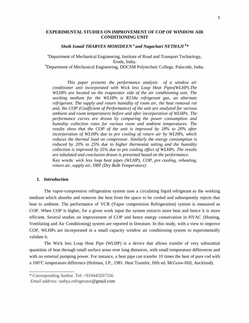
A schematic diagram of the experimental apparatus is shown in fig. 2. The test loop consists of
Fig.2-Schematic diagram of the experimental apparatus.1: Anemometer (0.4-30m/s), 2:
Thermometer (0-100°C) and Hygrometer (0-99%), 3: Air Conditioner and humidifier, 4:
Hygrometer (0-100%) and thermometer (0-100°C), 5: Thermometer (0-100 °C) and Hygrometer (0-
99%), 6: Watt meter (0-3000W), 7: Energy meter (5-20A), 8: Supply air, 9: Return air, 10:
Standard test chamber, 11:Reheating section of WLHP, 12:Cooling coil, 13: Pre-cooling section of
WLHP, 14: Measuring jar, 15: Evaporator coil, 16: Condenser coil, 17:Supply mains, 18: Ambient,
19:Voltmeter (0-240v ac), 20:Ammeter (0-20A).
5
12
4
8
9
10
1516
18
3
514
AV
17 6 19 7 20
DATA LOGGER
11 12 13

5
3350watt cooling capacity window A/C unit equipped with WLHPs on evaporator side, humidity
collection system and data acquisition system. The humidity collecting system measures the amount of
water vapor condensed at the evaporator due to pre cooling of return air by the evaporator section of
WLHPs and further cooling at evaporator coil of the A/C unit.
3.3 Operating conditions
Experiments were conducted on the above setup before and after activating the WLHPs. For the
given ambient conditions (DBT, RH) keeping the supply air velocity constant, the return air temperature,
return humidity, supply humidity and power consumed were recorded after bringing the room to steady
state condition. The data were obtained using the digital data acquisition system. The enthalpy of return
air before and after activating the WLHPs (hrb, hra), the enthalpy of supply air before and after activating
the WLHPs (hsb,hsa),the coefficient of performance before and after activating the WLHPs
(COPb,COPa),difference in COP (dCOP) and the improvement in COP (iCOP)were computed using C
language program for the same return and supply air temperature. The data and the results were tabulated.
The uncertainty and accuracy of measurements are given in tab.1.
Table.1 Accuracy and uncertainty of measurements
Instruments Manufacturer Model Accuracy Uncertainty
Anemometer CE marked, Taiwan make Digital wane
probe
±2% 1%
Temperature and Humidity controller
A.S.Controls,Mumbai(ISO 9001-2008)
Digital Probe type
±2% 1%
Kilowatt hr. meter Bentex Eletronics, New
Delhi(ISO 9001-2008)
Digital ± 0.11% ±0.17
Watt meter Bentex Electronics,New
Delhi(ISO 9001-2008)
Digital ±0.2% ±0.1%
Hygrometer A.S.Controls,Mumbai(ISO
9001-2008)
Digital ±1% ±0.1%
Test conditions
Test equipment: Window type air conditioner unit.
Model Window mountable
Make Samsung
Cooling power input 1.040 kW
Cooling capacity 3.350 kW
Air flow rate 0.3403 kgs-1
1. The outside air of dry bulb temperature of 29°C and relative humidity of 72% RH was considered,
which is a typical humid and tropical climate of countries like India, Sri Lanka, Myanmar etc.
6
2. The design average dry bulb temperature of 25°C and relative humidity of 50% RH was considered for
indoor condition.
3. The split air-conditioner mounted in the test chamber was used to restore the initial indoor condition
after each and every trial.
4. The cooling capacity of the test air conditioner is 3350 watt and the mass flow rate of air is assumed
constant.
5. The return air DBT, RH and the supply air DBT, RH were taken at the same point of supply and return
grills respectively. The effects of dead air pockets in the test chamber are ignored.
6. The real time data were used for computation using thermodynamic equations using MAT LAB and C
language.
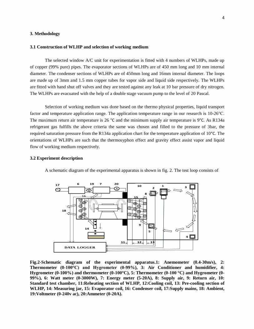
3.4 Data reduction and analysis
From the measured data the improvement of COP due to incorporation of WLHPs is calculated.
First the enthalpy of the humid air computed.
Enthalpy of moist air is calculated from the following relation
(1)
(2001 ASHRAE Fundamentals Handbook (SI)), where 1.006 is the specific heat of humid air at
constant pressure ( ) is the dry bulb temperature of the humid air, is the humidity ratio.
X [kW] (2)
Where, is the mass flow rate of air in kgs-1
Calculation of COP before installation of WLHPs
Enthalpy of return air before installation of heat pipes
(3)
Where is the given dry bulb temperature of return air before installation of WLHPs. is the
specific humidity of return air before installation of WLHPs.
Enthalpy of supply air before installation of heat pipes
(4)
Where, is the given dry bulb temperature of supply air before installation of WLHPs, being the
specific humidity of supply air before installation of WLHPs.
Then the difference in enthalpy of return and supply air (refrigerating effect)
(5)

7
COP of the test unit for given operating condition before incorporation of WLHPs is
(6)
Where, is power supplied before installation of heat pipes in [kW]
Calculation of COP after installation of WLHPs
As calculated above the enthalpy of return ( and supply ( ) air for the same dry bulb temperature
after installation of WLHP are computed. Then
(7)
Where, is power supplied after installation of heat pipes in kW, is difference enthalpy (
Then difference in COP of the test apparatus after and before installation of WLHPs is
(8)
Then the percentage improvement of COP is deduced as
(9)
4. Results and discussion
4.1 Effect of WLHPs on COP
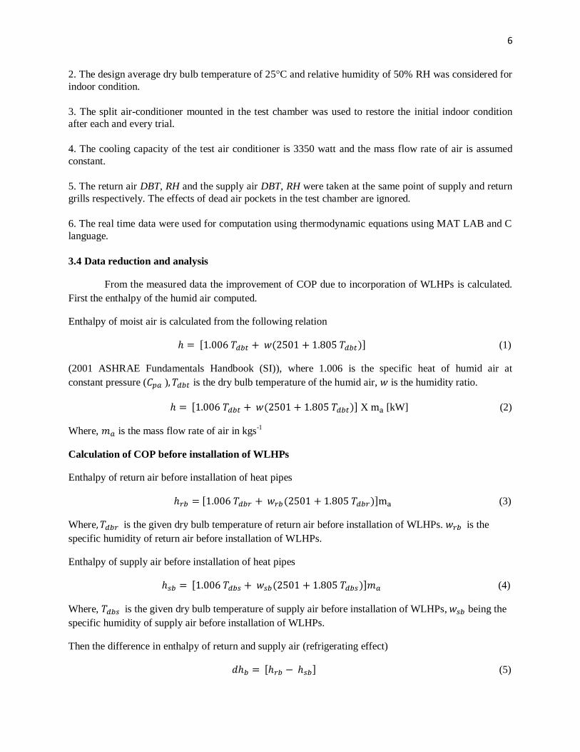
The variables which govern the performance of window air conditioner like the supply and return air humidity, power consumption are recorded with and without WLHP for different conditions of
experimentation by varying the return air dry bulb temperature. The COP is calculated before and after
incorporation of WLHPs and the results are plotted as graphs as shown in fig.3 (a-c).
Graph a
22 22.5 23 23.5 24 24.5 25 25.5 26 26.5
0
1
2
3
4
5
6
7
8
9
DBT deg C
WITHOUT WLHP: 22-09-2014, 1.00 PM , AMB- 29 Deg C/ 72%RH
WITH WLHP :23-09-2014 ,1.00 PM, AMB- 29Deg C/ 72% RH

8
Graph b
Graph c
Fig. 3(a-c)-Effects of WLHPs on COP. : Before installation, :After stallation,
Graph a: Trial conducted on 22nd
and 23rd
of Sep. 2014, Graph b: Trial conducted on 26
th and 27
th of
Sep 2014, Graph c: Trial conducted on 28th
and 29th
of 2014 under the stated ambient conditions.
Without heat pipes, at constant return air flow rate, when the room temperature is increased from
23 °C to 26°C the COP is found to improve. At a constant return air flow rate and room set temperature of
25°C when wickless loop heat pipes are incorporated with window air conditioner unit the COP is
improved from 3.18 to 3.95 as evident from the graph fig.4 a. This results in enhancement of COP by
22 22.5 23 23.5 24 24.5 25 25.5 26 26.5
0
1
2
3
4
5
6
7
8
9
DBT deg C
WITHOUT WLHP :26-09-2014, 1.00 PM, AMB- 29 Deg C/ 72% RH
WITH WLHP: 27-09-2014 ,1.00 PM, AMB- 29Deg C/ 72% RH
22 22.5 23 23.5 24 24.5 25 25.5 26 26.5
0
1
2
3
4
5
6
7
8
9
DBT deg C
WITHOUT WLHP 28-09-2014, 1.00 PM, AMB- 29 Deg C/ 72% RH
WITH WLHP 29-09-2014 ,1.00 PM, AMB- 29Deg C/ 72% RH

9
24.2 % than that of conventional one. The average improvement in COP is found to be from 18% to 20%
from the trials.
4.2 Effect of WLHP on energy consumption.
Without WLHPs, at constant air flow rate, when DBT is increased from 23°C to 26°C the energy
consumption decreases due to decreasing thermal load on compressor. With WLHP, when DBT is
increased from 23°C to 26°C the power consumption further decreases due to pre cooling function of the
heat pipes. The test air conditioner was subjected to trial run for 8 hours a day on different dates with
different room and ambient conditions and the energy consumptions were recorded. It is observed from
the bar chart fig.4, for the optimum room set temperature of 25°C the energy consumption is decreased
Fig. 4- Effects of WLHPs on energy consumption. -Before installation, -After installation, -% Improved
from 6 kWh to 4.5 kWh (for trials on 26, 27-09-2014). This results in 25% reduced energy consumption.
The average reduction in energy consumption is found to be 20-25% from the trials.
4.3 Effect of WLHP on humidity collection
The test air conditioner was subjected to trial run for 8 hours a day on different dates with
different room and ambient conditions and the humidity collections were recorded. As evident from the
bar chart fig.5, for the set room temperature of 25°C the humidity collection increases from 220 gm to
310 gm, improving by 40 %. The average improvement in humidity collection is found to be 35% from
the trial data.
2525
26-9-14 27-9-14 28-9-14 29-9-14 30-9-14 1-10-14 2-10-14 3-10-14
0
5
10
15
20
Date
En
ergy(k
Wh
)
% %% %
0
5
10
15
20
% E
nergy s
aved

10
Fig .5 -The effect of WLHP on humidity collection. -Before Installation, -After installation, -% Improved
4.4 Behavior of heat pipes
At start up, the temperature of the WLHP evaporator wall (TW), the cooling coil of A/C unit and
the condenser wall of WLHP are at the same temperature. For set room temperature of 25°C under steady
state condition, the wall temperature of WLHP’s evaporator is 28 °C (return air temperature), air outlet
temperature from the cooling coil is 9 °C and the WLHP’s condenser wall temperature is 10°C.The
saturation temperature of WLHP’s working medium (Tsat) being 10 °C, then the degree of super
heat{(TW-TSat) = (28-10)} is 18°C.This slightly super heated vapor reaches the condenser section of
WLHP through the vapor loop and condenses (at 10°C) and then returns back to the evaporator of WLHP
due to gravity and the cycle continues. As the gravity assists the quick and continuous return of liquid, the
WLHP evaporator will not starve for liquid and hence reliability of the WLHP is ensured.
4.5 The Psychrometric effect of WLHP
The psychrometric effect of incorporation of WLHP is shown in fig. 6(a-c). The WLHP’s pre-
(a) (b)
26-9-14 27-9-14 28-9-14 29-9-14 30-9-14 1-10-14 2-10-14 3-10-140
50
100
150
200
250
300
350
400
Con
den
saate
coll
ecti
on
(g
m)
Date
% % % %0
10
20
30
40
50
60
70
80
% im
pro
vem
en
t
w
DBT
T2T1
RSHF Line
ADPs
NORMAL A/C UNIT
R
w
DBT
T2T1
Cooling coil
LHP Evop.
ADPs C
RR1
Load
ratio line
LHP Cond.
WLHP INCORPRORATED A/C UNIT

11
(c )
Fig.6 a–The Psychrometric effects of normal A/C unit, (b, c)-The Psychrometric effects of WLHP
A/C unit, R: Return air, R1: Pre cooled return air from WLHP evaporator, S: Supply air from
cooling coil, C: Reheated supply air from WLHP condenser, dh: change in enthalpy, dx: change in
specific humidity, RSH: Room Sensible Heat.
-cool section sensibly cools the return air and the same is further cooled in the cooling coil of the air
conditioning unit below its saturation temperature at that pressure and hence more humidity is collected.
5. CONCLUTION
The incorporation of WLHPs in small capacity VCR system (domestic window a/c units) is done
and its performance is evaluated experimentally.
The results show the COP of the system for the room set temperature of 23-26°C is improved by
18-20 % .This is due to pre cool and reheat function of WLHPs and the consequent reduction in
thermal load on the compressor. The energy consumption is found to be reduced by 20-25% and
the humidity collection improved by 35%.
Also proved, the designed (3 bar, 10°C – R134 a) WLHPs are effective in temp range of 23-26°C.
ASHRAE standard for optimum human comfort level is approached.
Nomenclature
CP -specific heat [kJKg-1
K-1
]
COP -Coefficient of performance
h -specific enthalpy [kJKg-1
]
lh -latent heat gains [kW]
sh -sensible heat gains[kW]
m -mass flow rate of air [Kgs-1
]
p -pressure [bar]
P -power supplied to a/c unit [kW]
Tdbt -dry bulb temperature [°C]
Tsat -saturation temperature [°C]
Tdbr -return dry bulb temperature [°C]
Tdbs -supply dry bulb temperature [°C]
v -the volume flow rate [m3s
-1]
w -specific humidity [Kg/Kg of dry air]
Subscripts
a -after installation of WLHP
b - before installation of WLHP
r -return conditions of the air
x
h
kJ/kg
DBT°C
kg/kg of
dry air
ADP
R
R1
S
C
dX
MOLLIER DIAGRAM FOR WLHP INCORPORATED
A/C UNIT

12
s -supply condition of air
w -wall
Prefixes
d -difference
i -increase
Greek symbols
ρ - density [ Kg m-3
]
σ - surface tension[Nm-1
]
μ - viscosity [Nsm-2
]
Abbreviations
EER -energy efficiency ratio
HVAC -heating, ventilating and air
conditioning
RES -rate of energy saving
RH -relative humidity [%]
RHP -rotating heat pipe
VCR -vapor compression refrigeration
References
[1] Xiao ping Wu, Peter Johnson, Aliakbar kbarzadeh, Application of heat pipe heat exchanges to
humidity control in air-conditioning systems, Applied thermal engineering 17(1997),6,pp.561-
568 [2] D Etheridge, K Murphy, D Reay, A PCM heat pipe cooling system for reducing air conditioning
in buildings: review of options and report on field tests, Building services Engineering Research
and Technology, 27, (2006),1, pp.27-39 [3] Mostafa A. Abd El-Baky , Mousa M.Mohamed, Experimental study of heat pipes heat exchanger
for heat recovery in air conditioning applications, Ain Shams university, Cairo, Egypt, Scientific
Bulletin, 40(2006),4, pp.1119-1136
[4] Yau Y.H., Experimental thermal performance study of an inclined heat pipe heat exchanger operating in high humid tropical HVAC systems, International Journal of refrigeration,30
(2007), pp.1143-1152
[5] Hussam jouhara, Richard Meskimmon, Experimental investigation of wraparound loop heat pipe heat exchanger used in energy efficient air handling units, Energy,35(2010), pp. 4592-4599
[6] Supirattanakul S., Rittidech, Bubphachot B., Application of a closed-loop oscillating heat pipe
with check valves (CLOHP/CV) on performance enhancement in air conditioning system ,Energy and Building,43(2011), pp.1531-1535
[7] M. Ahmadzadehtalatapeh, Yau Y.H., Energy conservation potential of the heat pipe heat
Exchangers: experimental study and predications, International Journal of Engineering, 24
(2012), 3, pp.193-199 [8] Hussam jouhara, Hatem Ezzuddin, Thermal performance characteristics of a wraparound
loop heat pipe (WLHP) charged with R134A, Energy (2012), pp.1-11
[9] Yau Y.H.,Foo Y.C., Comparative study on evaporator heat transfer characteristics of revolving heat pipes filled with R134A, R22 and R410, International Communications in Heat
and Mass Transfer,38(2011), pp. 202-211
[10] Wan J.W.,Zhang J.L.,Zhang W.M., The effect of heat-pipe air-handling coil on energy
consumption in central air-conditioning System, Energy and Buildings, 39(2007), pp.1035-1040 [11] Yau Y.H., The heat pipe exchanger: a review of its status and its potential for coolness recovery
in tropical buildings, Building Services Engineering Research and Technology. 9(2008),4, pp.
291-310 [12] Yau Y.H., The use of a double heat pipe heat exchanger system for reducing energy consumption
of treating ventilation air in an operating theatre - A full year energy consumption model
simulation, Energy and Buildings,40(2008), pp.917-925 [13] Alklaibi A.M., Evaluating the possible configurations of incorporating the loop heat pipe into the
Air conditioning systems, International Journal of refrigeration, 31(2008), pp.807-815