Embed Size (px)
Citation preview

1
Experimental Results
from the
OECD Halden Reactor Project
Lecture 9.2
Wolfgang Wiesenack
OECD Halden Reactor Project, Norway
Joint ICTP-IAEA Workshop on
The Training in Basic Radiation Materials Science and itsApplication to Radiation Effects Studies and Development of
Advanced Radiation-Resistant Materials
Trieste, November 10-21, 2008
2
Overview
• Issues to be addressed and their interaction
• Phenomena influencing temperatures
• Fission gas release
• Dimensional changes and pellet-clad interaction
• Typical results of fuels testing
3
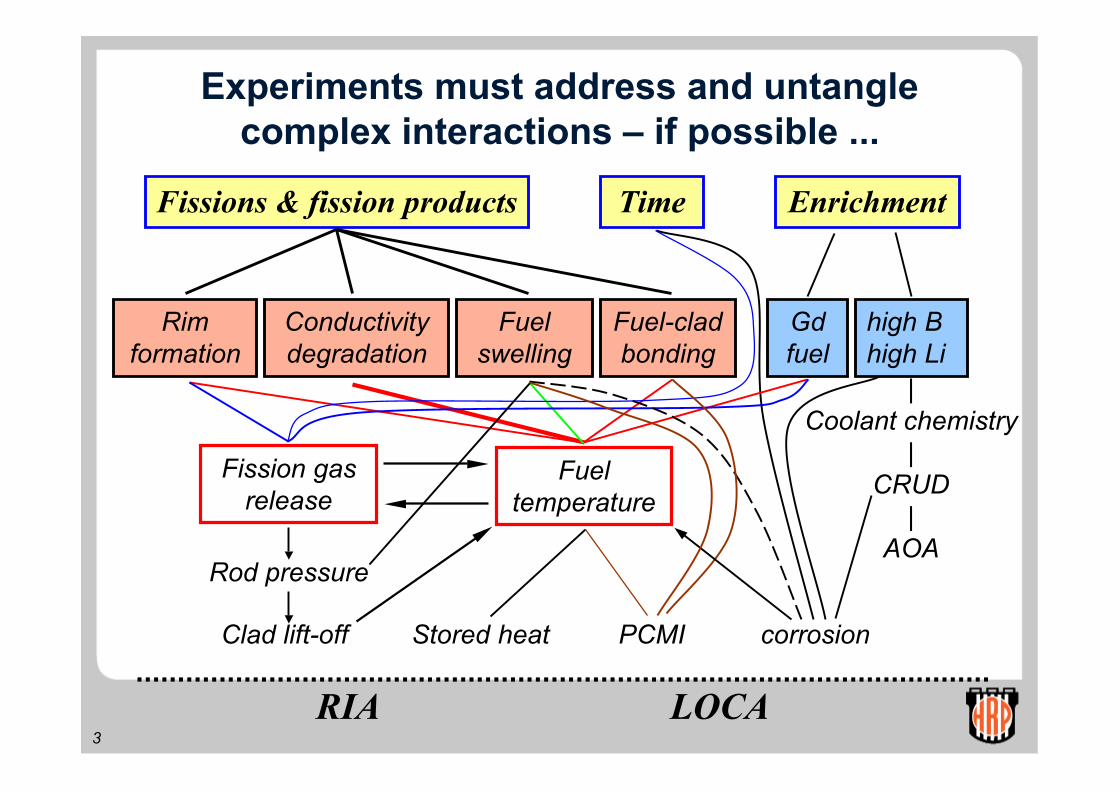
Experiments must address and untanglecomplex interactions – if possible ...
RIA LOCA
TimeFissions & fission products Enrichment
Rimformation
Fuel-cladbonding
Fuelswelling
Conductivitydegradation
Fission gasrelease
Fueltemperature
PCMIStored heat
Rod pressure
corrosion
Gdfuel
high Bhigh Li
Clad lift-off
|Coolant chemistry
|CRUD
|AOA

4
(Fuel) temperature overview
• Cladding temperature
• Gap size determination
• Gap conductance• Gap width
• Surface roughness
• Eccentricity
• Gas composition
• Pellet• Densification and swelling
• Thermal conductivity (degradation)

5
Cladding temperature
Measurement of the claddingtemperature is normally notwithin the scope of the HRPexperimental programme.However, if PCMI can beeliminated, details of claddingelongation behaviour can beused to qualify
• Coolant-clad heat transfercoefficient (Jens-Lottes notsatisfactory for low power)
• Zry-oxide conductivity Elongation of cladding with andwithout outer oxide layer
6
Gap size, relocation, gap conductance
• The determination of (effective) gap size and gapconductance has been the subject of many HRPseparate effects experiments which include:
• Determination of gap size by different techniques
• Systematic variation of gap conductance modelparameters such as gap size, surface roughness andfill gas composition
• The comprehensive set of experiments provide anextensive basis for gap conductance modelverification.

7
Gap size determination
• The size of the gap between fuel pellet and claddingcan be assessed by different direct and indirecttechniques:
• Clad squeezing (mechanical in-core device)
• Hydraulic diameter measurements
• Evaluation of onset of pellet-clad mechanical interaction
• Gas exchange and effect on fuel temperature

8
Hydraulic diameter measurements
The hydraulic diameterreflects the free volumein the fuel column.Normal changes are:
• initial pellet cracking andfragment relocation
• solid fission product fuelswelling
• development of aminimal HD as fuel andcladding accommodateto each other
Change of hydraulic diameter(free fuel column volume)

9
Hydraulic diameter measurements
• At zero power, high burnupfuel typically has a “gap”size reflecting thermalcontraction from theaccommodation power level
• When the accommodationpower level is approached,the hydraulic diameterdecreases at a higher rate,similar to the onset of PCMI
• Regular measurements in anumber of HBWRexperiments connected tothe gas flow system
The hydraulic diameter measurementsshow a linear decrease of ”gap” sizewith increasing power
High burnup fuel example

10
Cladding elongation of ex-PWRfuel (57 MWd/kgU) during severalstart-up / shut-down sequences
Gap size - onset of PCMI
Pellet-clad mechanicalinteraction undergoes variousphases. When the crackedfuel has accommodated to thecladding, the onset ofappreciable PCMI indicatesgap closure. The high burnupfuel example illustrates:
♣ cladding elongationdeviates little from freethermal expansion
♣ onset of interaction occursat previously reachedmaximum power (14-16kW/m)
11
Gap conductance
• Gap conductance models usually contain a numberof parameters that are accessible to experimentalset-ups. HRP separate effects experiments include:
• Systematic variation of gap size (50 – 400 mm)
• Variation of surface roughness of fuel and cladding
• Assessment of effect of eccentric pellet location
• Different initial fill gases (He, Ar, Xe) and their mixtures
• Variation of gap gas composition in-pile
• The associated data are indispensable for theverification of correct modelling of basic phenomenain fuel-clad gap heat transfer

12
Variation of gap size
The gap between fuel andcladding is a designparameter and in additionchanges with exposure.Numerous HRP experimentsprovide an extensive database for assessing the basicinfluence of gap size on gapconductance. The generaltrend is summarised in thegraph on the right for Heliumand Xenon as fill gas.
Influence of gap on fuel temperature
13
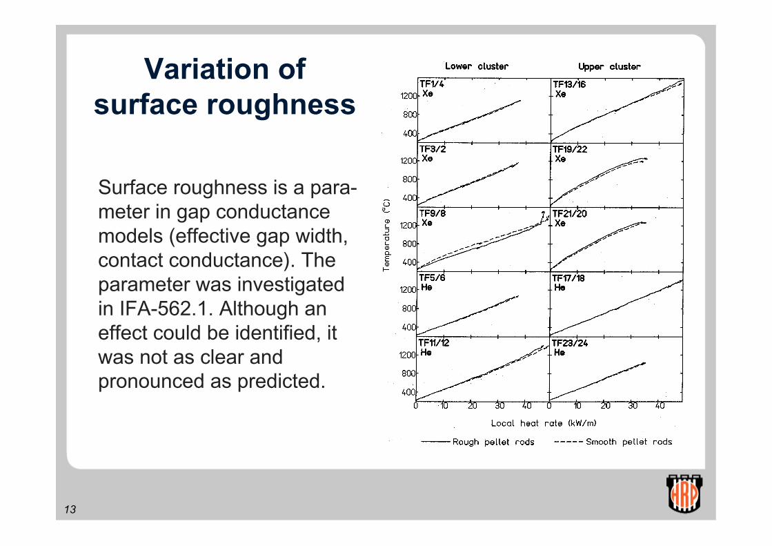
Variation ofsurface roughness
Surface roughness is a para-meter in gap conductancemodels (effective gap width,contact conductance). Theparameter was investigatedin IFA-562.1. Although aneffect could be identified, itwas not as clear andpronounced as predicted.
14
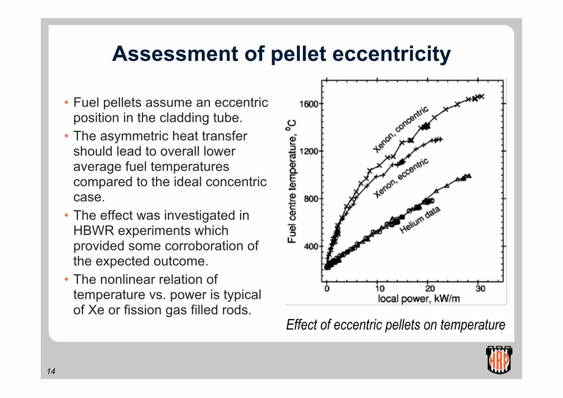
Assessment of pellet eccentricity
• Fuel pellets assume an eccentricposition in the cladding tube.
• The asymmetric heat transfershould lead to overall loweraverage fuel temperaturescompared to the ideal concentriccase.
• The effect was investigated inHBWR experiments whichprovided some corroboration ofthe expected outcome.
• The nonlinear relation oftemperature vs. power is typicalof Xe or fission gas filled rods.
Effect of eccentric pellets on temperature

15
Fill gas type and composition
The initial fuel rod helium fill gasis diluted by released fission gasresulting in decreased gap con-ductance. The effect and thefeedback on temperatures andfurther gas release needsaccurate modelling. A number ofexperiments were conducted inthe past where xenon or argonwere added to simulate variousdegrees of fission gas release.The results from several IFAsare summarised in the figure.
Influence of fill gas on fuel temperature
30 kW/m
20 kW/m

16
Fill gas pressure, extrapolation length
• Gap conductance modelsemploy the concept of‘extrapolation length’ toaccount for imperfect heattransfer between gas andsolid
• The correction dependson pressure
• The effect has beenassessed experimentally
• It shows some burnupdependence, possibly dueto changes in number offuel cracks

17
Numerous experiments address fueldensification and swelling. The primaryinstrument is the fuel stack elongationdetector. Densification information canalso be derived from rod pressuremeasurements.
Densification & swelling
The data of the example stem from adisk fuel irradiation and show adependence on
• grain size (small vs. large grain)• irradiation temperature• fuel fabrication (for MOX fuel)

18
Thermal Conductivity, DegradationDevelopment of Temperature in UO2 and (U,Gd)O2 Fuel
The comparative irradiation shows the conduc-tivity difference of the two types of fuel as wellas the change of conductivity with burnup.
Measured fuel centre-line temperatures arelinked to the thermalconductivity of the fuel.Numerous fuel rodsequipped withthermocouples (UO2,MOX, Gd-fuel, IMF…)constitute a large database for the evaluationof various effectsinfluencing conductivity.
19
Fission gas release overview
• Release onset
• Release kinetics
• Grain size
• Gas mixing
Measurements:
• Rod pressure
• Gamma spectroscopy
• Rod puncturing and gas analysis

20
Fission gas release onset
• Irradiation of fresh and highburnup fuel (segments fromLWRs)
• lnstrumentation:- fuel thermocouple- rod pressure sensor
• Stepwise power / temp.increase to establish onset offission gas release
• Simultaneous measurementof fuel temperature (mostimportant parameter)
Temperature history and measuredrod pressure (fission gas release)

21
• Steady state power forlong-term kinetics
• For high burnup fuel,power dips arenecessary in order toobtain communicationwith the plenum (tightfuel column)
• Envelope of releasecurve indicates diffusioncontrolled release
Temperature and FGR history
Fission gas release kinetics

22
Influence of grains size on gas release
• According to diffusionmodel, in general anincreased grain sizewill result in reducedfission gas release
• At higher power andFGR >10%, grain sizeincrease is lesseffective
• Satisfactory predictionwith diffusion-basedFGR model (Turnbull)
Measured and predicted FGR forUO2 fuel with different grain sizes

23
Gas mixing in a fuel rod (I)
• Released fission gas has to diffuse to the rodplenum
• A temporary strong dilution of the fill gas in the fuelcolumn may result …
• ... and cause increased fuel temperatures andpositive feedback on fission gas release.
• Gas mixing behaviour and feedback has beeninvestigated in different ways:
• Injection of argon at one end and tracing the equilibration
• Causing FGR and monitoring of the temperature response

24
Gas mixing in a fuel rod (II)
• Argon injected in lower plenum
• Diffusion to upper plenum, equilibration
• Temperature response measured
25
PCMI overview
• How to measure PCMI and fuel stack properties
• Development of onset of interaction(fresh, low to medium, high burnup fuel)
• Long-term PCMI• cladding elongation and fuel swelling
• Axial ratcheting

26
Possibilities to measure PCMIand fuel stack properties
• Primary measurements
• Diameter gauge, 3-pointfeeler moving along thelength of the rod, µm sens.
• Cladding elongation sensor,LVDT principle, frequentmeasurements, reliable
• Secondary measurements
• Gas flow, hydraulic diameter
• Noise analysis (elongationand neutron detector)
Axial and diametral deformation showsimilar trends in small gap rods

27
PCMI & fueldesign
PCMI is influenced by anumber of fuel designparameters, e.g.:
• Pellet end shape (dished,flat ended, chamfered)
• Pellet length (L/D)
• Hold-down spring force
A number of experimentshave addressed these andother parameters. Otherexperiments deal with ridgeformation and rampingbehaviour.
28
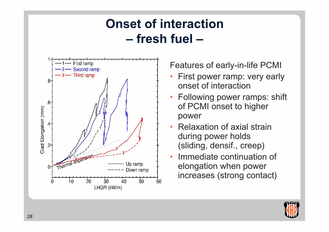
Onset of interaction– fresh fuel –
Features of early-in-life PCMI• First power ramp: very early
onset of interaction• Following power ramps: shift
of PCMI onset to higherpower
• Relaxation of axial strainduring power holds(sliding, densif., creep)
• Immediate continuation ofelongation when powerincreases (strong contact)

29
Onset of interactionFuel-clad accommodation
• The onset of interactionmoves to lower powerwith increasing burnupand decreasing power
• The accommodation offuel and cladding toeach other result insmall ‘interaction tails’as long as power doesnot exceed previouslyreached levels.

30
Initial PCMI – Re-instrumentedPWR fuel 52 MWd/kgUO2
• No appreciable PCMI for thefirst ramp since theconditioning power of 20kW/m is not exceeded
• Linear elongation part ismore than calculated forthermal expansion
• Some re-conditioning during2.5 MWd/kg burnupincrement between secondand last ramp

31
Axial racheting
BurnupMWd/kgUO2
-0- 29.0-1- 29.5-2- 30.0-3- 31.0-4- 32.5-5- 34.0-6- 34.0-7- 34.0-8- 35.0-9- 37.5
The slight mismatchbetween release andonset of interactioncauses axial ratchetingand elongation peaks
32
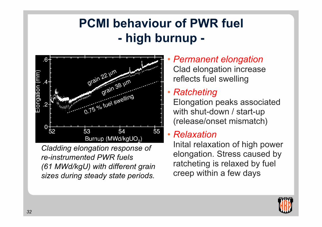
PCMI behaviour of PWR fuel- high burnup -
• Permanent elongationClad elongation increasereflects fuel swelling
• RatchetingElongation peaks associatedwith shut-down / start-up(release/onset mismatch)
• RelaxationInital relaxation of high powerelongation. Stress caused byratcheting is relaxed by fuelcreep within a few days
Cladding elongation response ofre-instrumented PWR fuels(61 MWd/kgU) with different grainsizes during steady state periods.

33
Typical Results Fuels Testing
• Conductivitydegradation
• Fission gas release
• Cladding creep
• Overpressure – clad lift-off
To
tal d
iam
eter
ch
ang
e (µ
m)
Full power hours
o
o597
629
UO2, MOXGd-UO2

34
The END