Embed Size (px)
Citation preview
Volume 1, Number 2 (November 2005) p. 103 - 126 ISSN 1809-1121
Revista IBRACON de Estruturas
IBRACON Structural Journal
Experimental research of a new CFRP-based shear strengthening technique for reinforced concrete beams Verificação experimental de uma nova técnica de reforço ao corte com CFRP para vigas de betão armado
S. DIASa [email protected]
J. BARROSa [email protected]
a School of Engineering of Minho University, 4800-058, Guimarães, Portugal
© 2005 IBRACON
Abstract A Near Surface Mounted (NSM) strengthening technique was developed to increase the shear resistance of reinforced concrete beams. The NSM technique is based on fixing, by epoxy adhesive, CFRP laminate strips into saw-cut slits on the concrete cover of lateral surfaces of the beams. To assess the efficacy of this technique, an experimental program of four-point bending tests was carried out. Each of the four tested series was composed of five beams: without any shear reinforcement; reinforced with conventional steel stirrups; strengthened with U strips of wet lay-up CFRP sheets; and two beams strengthened with precured laminate strips of CFRP, one of them with laminates positioned at 90º and the other with laminates positioned at 45º in relation to the beam axis. Influences of the laminate strip percentage, laminate strip inclination and beam height on the efficacy of the NSM technique were analyzed. This efficacy was assessed not only in terms of the increase of maximum load and deflection at beam rupture, but also in terms of the beam strength performance per unit length of the applied material. © 2005 IBRACON. All rights reserved.
Keywords: shear strengthening; shear failure; concrete; CFRP; NSM laminates; efficacy.
Resumo Neste trabalho apresenta-se a técnica de reforço ao corte baseada na inserção de laminados de CFRP em finos entalhes efectuados nas faces laterais de vigas de betão armado. De forma a validar a técnica de reforço proposta foi realizado um programa experimental que englobou vigas sem qualquer armadura transversal, vigas com estribos verticais de aço, vigas em que o reforço ao corte foi materializado por intermédio de faixas discretas de manta de CFRP coladas externamente em forma de U, e vigas reforçadas ao esforço transverso com laminados de CFRP dispostos verticalmente ou inclinados a 45º, inseridos em entalhes efectuados no betão de recobrimento das faces laterais da viga. Os parâmetros avaliados foram a percentagem de CFRP, a orientação do reforço e a altura da viga. O desempenho da nova técnica de reforço foi avaliado quer em termos mecânicos quer em termos da quantidade de material de CFRP utilizado. © 2005 IBRACON. All rights reserved.
Palavras-chave: reforço ao corte; rotura por corte; betão; CFRP; laminados inseridos; eficácia.
12
Experimental research of a new CFRP-based shear strengthening technique for reinforced concrete beams Verificação experimental de uma nova técnica de reforço ao corte com CFRP para vigas de betão armado
104 IBRACON Structural Journal ⋅ 2005 ⋅ 1 ⋅ n.2
1 Introduction There are several reasons that explain the need for shear strengthening of reinforced concrete structural elements: change of use (higher exigencies in terms of load cases and/or load combinations), errors in the design and/or construction phase, decrease of the material’s performances in resulting of ageing effects (concrete carbonatation and steel corrosion); the continuous upgrading of design codes; damages caused by earthquakes, fires, explosions, inundations or vandalism acts. Furthermore, there are some cases when shear strengthening is needed in resulting of the flexural upgrading. Shear failure mode must be avoided since it occurs suddenly and in a brittle manner.
Since the beginning of the 1990’s, Carbon Fiber Reinforced Polymer (CFRP) materials have being replacing conventional materials in several structural strengthening interventions. There are several reasons that justify the increase use of CFRP: low weight, high durability and tensile strength, and the good fatigue behaviour. Due to its low weight, CFRP materials are easier of manipulating and transporting than conventional reinforcing materials like steel plates. CFRP have been disponibilized with unlimited dimensions (this is not possible on steel plates), which eliminates the necessity of doing joint ligaments between adjacent strengthening elements. Since CFRP have greater resistance to corrosion than steel, they can be used in aggressive environments. The high tensile strength and Young’s modulus of theses materials can be used to design a strengthening solution of minimal interference from the architectural point of view. Due to its flexibility, wet lay-up CFRP sheets can be applied on curved shape structures, which is too difficult of assuring with conventional steel plates, and, if possible, too expensive. Moreover, when compared to conventional strengthening techniques, those based on the use of CFRP are faster and easier to apply.
For the shear strengthening, CFRP materials can be applied according to the followings two main techniques: bonding wet lay-up sheets and laminates to the exterior faces of the elements to be strengthened (EBR); installing CFRP rods into groves opened on the concrete cover of the elements to strengthen (Dias and Barros [1]). This last technique is designated as Near Surface Mounted (NSM).
Adopting EBR technique (sheets and laminates), several researchers (Taerwe et al. [2]; Chaallal et al. [3]; Triantafillou [4]; Khalifa et al. [5]; Triantafillou and Antonopoulos [6]; Etman et al. [7] and Basler et al. [8]) have verified that the shear resistance of concrete beams can significantly be increased. However, due to premature debonding of the CFRP systems, the maximum strain mobilized by these systems is well below their ultimate strain. Furthermore, these failure modes occur suddenly and in a brittle manner. In addition, EBR systems are susceptible to fire and acts of vandalism.
To overcome these drawbacks some attempts have been doing, a promising one was proposed by De Lorenzis and Nanni [9]. Using rods of CFRP embedded into grooves made on the concrete cover of the lateral beam’s faces, a significant increase of the load carrying capacity of the beams was obtained. Since according to NSM, CFRP are introduced into the concrete cover, they stay well protected
against the influence of undesired agents. Open grooves of enough dimensions to install CFRP rods is the critical phase of this technique due to the time it requires.
Barros and Dias [10] proposed a similar strengthening technique but, instead of rods, laminate strips were used. This technique is based on installing CFRP laminate strips into thin pre-cut slits opened on the concrete cover. This strengthening technique has already been used to increase the load carrying capacity of concrete elements failing in bending (Ferreira [11], Fortes et al. [12] and Barros et al. [13]). The obtained results showed that this technique is very effective for the strengthening of concrete structures and is more efficient than EBR technique. This higher effectiveness is derived from the larger CFRP laminate-concrete bond stress values that can be mobilized in the NSM technique. The NSM effectiveness for the flexural strengthening of reinforced concrete beams is not only in terms of the beam load carrying capacity, but also in terms of deflection capacity at beam failure. The bond behavior was also well characterized by pullout bending tests (Sena-Cruz and Barros [14]). The bond strength values registered in the NSM laminates were much higher than the values reported for the laminates applied according to EBR technique.
2 Experimental program To assess the performance of the NSM technique to increase the shear resistance of reinforced concrete beams failing in shear, an experimental program was carried out (Dias and Barros [15]). Influences of the beam’s depth, CFRP strengthening ratio and orientation of the CFRP laminates on the efficacy of the NSM technique were analyzed. The tests were carried out at the Structural Laboratory (LEST) of the Civil Engineering Department of Minho University.
2.1 Beam models The experimental program is composed by two series of reinforced concrete beams (A series and B series). A series is constituted by beams of 0.15x0.30 m2 cross section, length of 1.6 m and span of 1.5 m. B series is composed by beams of 0.15x0.15 m2 cross section, length of 1.0 m and span of 0.9 m. The shear span, a, on the both series of beams was two times the height of the beams (a/h = 2). Each one of these series is composed by two sub-series: one with 4φ10 longitudinal tensile steel bars and the other with 4φ12. The beams of the experimental program had 2φ6 steel bars at top surface.
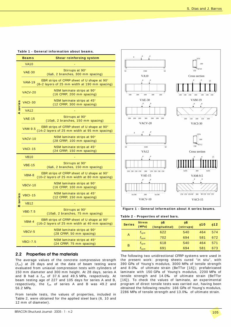
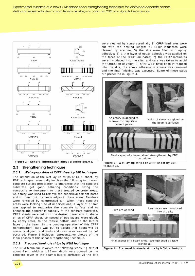
In each series, a conventional (steel stirrups) and the following three CFRP-based reinforcing systems were applied: a beam wrapped with U strips of CFRP sheets (EBR technique) and two beams strengthened by laminate strips of CFRP installed into slits opened on the concrete cover of the lateral surfaces of the concrete beams (NSM technique). The laminates were at 90º with the beam axis in one of these two beams and at 45º in the other beam. The shear reinforcement of the applied four reinforcing systems was evaluated in order to assure that all beams would fail by shear, at a similar load carrying capacity. Figures 1 and 2 and Table 1 include information about the tested beams.
S. Dias and J. Barros
IBRACON Structural Journal ⋅ 2005 ⋅ 1 ⋅ n.2 105
Table 1 - General information about beams.
Beams Shear reinforcing system
VA10 -
VAE-30 Stirrups at 90°
(6φ6, 2 branches, 300 mm spacing)
VAM-19 EBR strips of CFRP sheet of U shape at 90°
(8×2 layers of 25 mm width at 190 mm spacing)
VACV-20NSM laminate strips at 90°
(16 CFRP, 200 mm spacing)
VACI-30 NSM laminate strips at 45°
(12 CFRP, 300 mm spacing)
VA12 -
VAE-15 Stirrups at 90°
(10φ6, 2 branches, 150 mm spacing)
VAM-9.5EBR strips of CFRP sheet of U shape at 90°
(14×2 layers of 25 mm width at 95 mm spacing)
VACV-10NSM laminate strips at 90°
(28 CFRP, 100 mm spacing)
A s
eri
es
VACI-15 NSM laminate strips at 45°
(24 CFRP, 150 mm spacing)
VB10 -
VBE-15 Stirrups at 90°
(6φ6, 2 branches, 150 mm spacing)
VBM-8 EBR strips of CFRP sheet of U shape at 90°
(10×2 layers of 25 mm width at 80 mm spacing)
VBCV-10NSM laminate strips at 90°
(16 CFRP, 100 mm spacing)
VBCI-15 NSM laminate strips at 45°
(12 CFRP, 150 mm spacing)
VB12 -
VBE-7.5 Stirrups at 90°
(10φ6, 2 branches, 75 mm spacing)
VBM-4 EBR strips of CFRP sheet of U shape at 90°
(16×2 layers of 25 mm width at 40 mm spacing)
VBCV-5 NSM laminate strips at 90° (28 CFRP, 50 mm spacing)
B s
eri
es
VBCI-7.5NSM laminate strips at 45° (24 CFRP, 75 mm spacing)
2.2 Properties of the materials The average values of the concrete compressive strength (fcm) at 28 days and at the date of beam testing were evaluated from uniaxial compression tests with cylinders of 150 mm diameter and 300 mm height. At 28 days, series A and B had a fcm of 37.6 and 49.5 MPa, respectively. At beam testing age of 227 and 105 days for series A and B, respectively, the fcm of series A and B was 49.2 and 56.2 MPa.
From tensile tests, the values of properties, included in Table 2, were obtained for the applied steel bars (6, 10 and 12 mm of diameter).
VACI-30VACV-20
200
300
50
VAM-19
150200200300200200 200 300
300300300
VAE-30PP
300 190 190190
300150300
190 190 190
P
300
P
Cross sectionVA10PP
1500 50
25PP
1504∅10
300
PPa2∅6
VACV-10 VACI-15
50
150
6x95
6x1006x100 300 150
150150150 300150 150150
VAE-15P P
150150
80150 15015080 150300
6x95300
VAM-9.5PP
VA12P P
1500 50
Cross section25P P
300
1504∅12
P Pa2∅6
Figure 1 - General information about A series beams.
Table 2 - Properties of steel bars.
Series Stress (MPa)
φ6 (longitudinal)
φ6 (stirrups)
φ10 φ12
fsym 622 540 464 574 A
fsum 702 694 581 672
fsym 618 540 464 571 B
fsum 691 694 581 673
The following two unidirectional CFRP systems were used in the present work: prepreg sheets cured “in situ”, with 390 GPa of Young’s modulus, 3000 MPa of tensile strength and 8.0‰ of ultimate strain (BeTTor [16]); prefabricated laminate with 150 GPa of Young’s modulus, 2200 MPa of tensile strength and 14.0‰ of ultimate strain (BeTTor [16]). To check the values of laminate, an experimental program of direct tensile tests was carried out, having been obtained the following results: 166 GPa of Young’s modulus, 2286 MPa of tensile strength and 13.0‰ of ultimate strain.
12
Experimental research of a new CFRP-based shear strengthening technique for reinforced concrete beams Verificação experimental de uma nova técnica de reforço ao corte com CFRP para vigas de betão armado
106 IBRACON Structural Journal ⋅ 2005 ⋅ 1 ⋅ n.2
150
100100 100
150
50
100100 100300
VBCV-1015080150 80 300
VBCI-15
8060150150
P
300
P
VBE-158080 6080
P
30080 80
P
VBM-8
P
900
P
VB1050
150
4∅10
25P
150
P
Cross section
a PP2∅6
4∅12
VBCI-7.5
Cross section
6x50 300
VBCV-53x75 406x50 300
P P
4x75 300
VBE-7.5P
7x40 3004x75
VBM-4
P P
90050
VB12P
50 150
3x7540
P
7x40
P 25
150
2∅6PPa
Figure 2 - General information about B series beams.
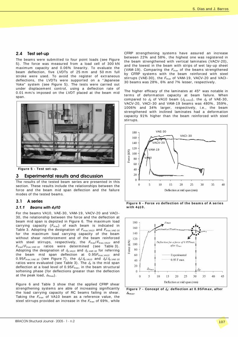
2.3 Strengthening techniques 2.3.1 Wet lay-up strips of CFRP sheet by EBR technique The installation of the wet lay-up strips of CFRP sheet, by EBR technique, essentially involves the following two tasks: concrete surface preparation to guarantee that the concrete substrate get good adhering conditions; fixing the composite reinforcement to these treated concrete areas. An emery was used to remove the superficial cement paste and to round out the beam edges in these areas. Residues were removed by compressed air. When these concrete areas were looking free of imperfections, a layer of primer was applied to regularize the concrete surface and to enhance the adherence capacity of the concrete substrate. CFRP sheets were cut with the desired dimension. U shape strips of CFRP sheet, composed of two layers, were glued, by epoxy resin, to the tensile bottom and to the lateral faces of the beam. In the bonding operation of this CFRP reinforcement, care was put to assure that fibers will be correctly aligned, and voids and resin in excess will be not occurred. Figure 3 includes representative photos of the main phases of this shear strengthening technique.
2.3.2 Precured laminate strips by NSM technique The NSM technique involves the following steps: 1) slits of about 5 mm width and 15 mm depth were opened on the concrete cover of the beam’s lateral surfaces; 2) the slits
were cleaned by compressed air; 3) CFRP laminates were cut with the desired length; 4) CFRP laminates were cleaned by acetone; 5) the slits were filled with epoxy adhesive; 6) a thin layer of epoxy adhesive was applied on the faces of the CFRP laminates; 7) the CFRP laminates were introduced into the slits, and care was taken to avoid the formation of voids; 8) after CFRP have been introduced into the slits, the epoxy adhesive in excess was removed and the final finishing was executed. Some of these steps are presented in Figure 4.
An emery is applied to remove the superficial
cement paste
Strips of sheet are glued on the beam’s surfaces
Final aspect of a beam shear strengthened by EBR
technique
Figure 3 - Wet lay-up strips of CFRP sheet by EBR technique.
Slits are opened Laminates are introduced
into the slits
Final aspect of a beam shear strengthened by NSM
technique
Figure 4 - Precured laminate strips by NSM technique.
S. Dias and J. Barros
IBRACON Structural Journal ⋅ 2005 ⋅ 1 ⋅ n.2 107
2.4 Test set-up The beams were submitted to four point loads (see Figure 5). The force was measured from a load cell of 300 kN maximum capacity and 0.06% linearity. To evaluate the beam deflection, five LVDTs of 25 mm and 50 mm full stroke were used. To avoid the register of extraneous deflections, the LVDTs were supported on a “Japanese Yoke” system (see Figure 5). The tests were carried out under displacement control, using a deflection rate of 0.01 mm/s imposed on the LVDT placed at the beam mid span.
Figure 5 - Test set-up.
3 Experimental results and discussion The results of the tested beam series are presented in this section. These results include the relationships between the force and the beam mid span deflection and the failure modes of the tested beams.
3.1 A series 3.1.1 Beams with 4φ10 For the beams VA10, VAE-30, VAM-19, VACV-20 and VACI-30, the relationship between the force and the deflection at beam mid span is depicted in Figure 6. The maximum load carrying capacity (Fmax) of each beam is indicated in Table 3. Adopting the designation of Fmax,VA10 and Fmax,VAE-30 for the maximum load carrying capacity of the beam without shear reinforcement and of the beam reinforced with steel stirrups, respectively, the Fmax/Fmax,VA10 and Fmax/Fmax,VAE-30 ratios were determined (see Table 3). Adopting the designation of δp,VA10 and δp,VAE-30 for referring the beam mid span deflection at 0.95Fmax,VA10 and 0.95Fmax,VAE-30 (see Figure 7), the δp/δp,VA10 and δp/δp,VAE-30 ratios were evaluated (see Table 3). The δp is the mid span deflection at a load level of 0.95Fmax, in the beam structural softening phase (for deflections greater than the deflection at the peak load, δFmax).
Figure 6 and Table 3 show that the applied CFRP shear strengthening systems are able of increasing significantly the load carrying capacity of RC beams failing in shear. Taking the Fmax of VA10 beam as a reference value, the steel stirrups provided an increase in the Fmax of 69%, while
CFRP strengthening systems have assured an increase between 22% and 58%, the highest one was registered in the beam strengthened with vertical laminates (VACV-20), and the lowest in the beam with strips of wet lay-up sheet (VAM-19). Comparing the Fmax of the beams strengthened by CFRP systems with the beam reinforced with steel stirrups (VAE-30), the Fmax of VAM-19, VACV-20 and VACI-30 beams was 28%, 6% and 7% lesser, respectively.
The higher efficacy of the laminates at 45º was notable in terms of deformation capacity at beam failure. When compared to δp of VA10 beam (δp,VA10), the δp of VAE-30, VACV-20, VACI-30 and VAM-19 beams was 480%, 359%, 1006% and 34% larger, respectively, i.e., the beam strengthened with inclined laminates had a deformation capacity 91% higher than the beam reinforced with steel stirrups.
0
20
40
60
80
100
120
140
160
180
0 5 10 15 20 25 30 35 40
Deflection at mid span (mm)
Forc
e (k
N)
Figure 6 - Force vs deflection of the beams of A series with 4φ10.
Figure 7 - Concept of δp: deflection at 0.95Fmax, after δFmax.
VAM-19
VACI-30
VAE-30
VACV-20
VA10
12
Experimental research of a new CFRP-based shear strengthening technique for reinforced concrete beams Verificação experimental de uma nova técnica de reforço ao corte com CFRP para vigas de betão armado
108 IBRACON Structural Journal ⋅ 2005 ⋅ 1 ⋅ n.2
Table 3 - Main results of the beams of A series with 4φ10.
Beams Fmax*
(kN) Fmax/ Fmax, VA10 Fmax/ Fmax, VAE-30
δP
(mm) δP/ δP,VA10 δP/ δP,VAE-30
VA10 100.40 1.00 0.59 2.80 1.00 0.17
VAE-30 169.35 1.69 1.00 16.25 5.80 1.00
VAM-19 122.06 1.22 0.72 3.75 1.34 0.23
VACV-20 158.64 1.58 0.94 12.86 4.59 0.79
VACI-30 157.90 1.57 0.93 30.96 11.06 1.91
* Fmax = 2P (See Figure 1).
VA10
VAE-30
VACI-30
VACV-20
VAM-19
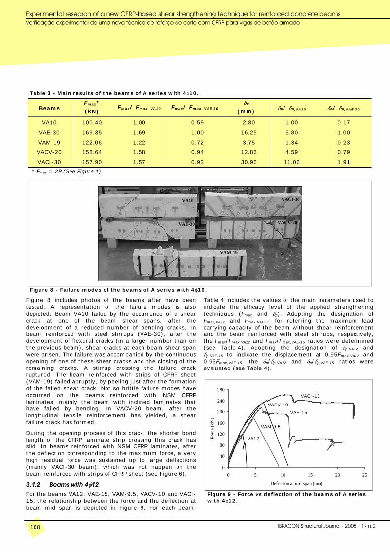
Figure 8 - Failure modes of the beams of A series with 4φ10.
Figure 8 includes photos of the beams after have been tested. A representation of the failure modes is also depicted. Beam VA10 failed by the occurrence of a shear crack at one of the beam shear spans, after the development of a reduced number of bending cracks. In beam reinforced with steel stirrups (VAE-30), after the development of flexural cracks (in a larger number than on the previous beam), shear cracks at each beam shear span were arisen. The failure was accompanied by the continuous opening of one of these shear cracks and the closing of the remaining cracks. A stirrup crossing the failure crack ruptured. The beam reinforced with strips of CFRP sheet (VAM-19) failed abruptly, by peeling just after the formation of the failed shear crack. Not so brittle failure modes have occurred on the beams reinforced with NSM CFRP laminates, mainly the beam with inclined laminates that have failed by bending. In VACV-20 beam, after the longitudinal tensile reinforcement has yielded, a shear failure crack has formed.
During the opening process of this crack, the shorter bond length of the CFRP laminate strip crossing this crack has slid. In beams reinforced with NSM CFRP laminates, after the deflection corresponding to the maximum force, a very high residual force was sustained up to large deflections (mainly VACI-30 beam), which was not happen on the beam reinforced with strips of CFRP sheet (see Figure 6).
3.1.2 Beams with 4φ12 For the beams VA12, VAE-15, VAM-9.5, VACV-10 and VACI-15, the relationship between the force and the deflection at beam mid span is depicted in Figure 9. For each beam,
Table 4 includes the values of the main parameters used to indicate the efficacy level of the applied strengthening techniques (Fmax and δp). Adopting the designation of Fmax,VA12 and Fmax,VAE-15 for referring the maximum load carrying capacity of the beam without shear reinforcement and the beam reinforced with steel stirrups, respectively, the Fmax/Fmax,VA12 and Fmax/Fmax,VAE-15 ratios were determined (see Table 4). Adopting the designation of δp,VA12 and δp,VAE-15 to indicate the displacement at 0.95Fmax,VA12 and 0.95Fmax,VAE-15, the δp/δp,VA12 and δp/δp,VAE-15 ratios were evaluated (see Table 4).
0
40
80
120
160
200
240
280
0 5 10 15 20 25
Deflection at mid span (mm)
Forc
e (k
N)
Figure 9 - Force vs deflection of the beams of A series with 4φ12.
VAM-9.5
VACI-15
VAE-15
VACV-10
VA12
S. Dias and J. Barros
IBRACON Structural Journal ⋅ 2005 ⋅ 1 ⋅ n.2 109
Figure 9 and Table 4 show that the applied CFRP shear strengthening systems were capable of increasing significantly the load carrying capacity of the reference beam of the present series. Taking Fmax of VA12 beam as a reference value, the steel stirrups provided an increase of 85% in the Fmax, while CFRP strengthening systems have assured an increase between 54% and 125%, the highest one was registered in the beam strengthened with inclined laminates (VACI-15), and the lowest one in the beam with strips of wet lay-up sheet (VAM-9.5). Taking the Fmax of the beam reinforced with steel stirrups (VAE-15) as a basis of
comparison, the Fmax of VAM-9.5, VACV-10 and VACI-15 beams was 17% smaller, 9% and 22% larger, respectively.
The higher efficacy of the laminates at 45º was also notable in terms of deformation capacity at beam failure. When compared to the δp of VA12 beam (δp,VA12), the δp of the beams reinforced with steel stirrups, inclined laminates, vertical laminates and strips of sheet was 131%, 329%, 145% and 79% larger, respectively, i.e., the beam strengthened with inclined laminates had 85% higher deformation capacity than the beam reinforced with steel stirrups.
Table 4 - Main results of the beams of A series with 4φ12.
Beams Fmax*
(kN) Fmax/ Fmax, VA12 Fmax/ Fmax, VAE-15
δP
(mm) δP/ δP,VA12 δP/ δP,VAE-15
VA12 116.50 1.00 0.54 2.74 1.00 0.43
VAE-15 215.04 1.85 1.00 6.34 2.31 1.00
VAM-9.5 179.54 1.54 0.83 4.91 1.79 0.77
VACV-10 235.11 2.02 1.09 6.70 2.45 1.06
VACI-15 262.38 2.25 1.22 11.75 4.29 1.85
* Fmax = 2P (See Figure 1).
VA12
VAE-15
VACI-15
VACV-10
VAM-9.5
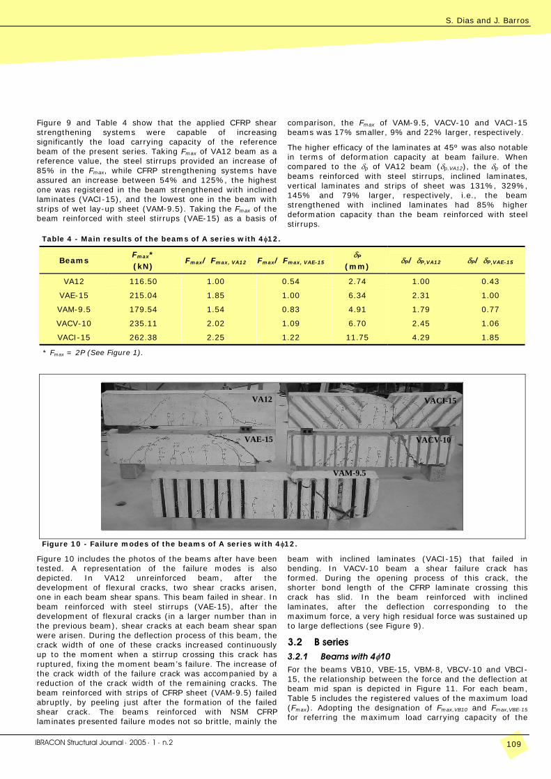
Figure 10 - Failure modes of the beams of A series with 4φ12.
Figure 10 includes the photos of the beams after have been tested. A representation of the failure modes is also depicted. In VA12 unreinforced beam, after the development of flexural cracks, two shear cracks arisen, one in each beam shear spans. This beam failed in shear. In beam reinforced with steel stirrups (VAE-15), after the development of flexural cracks (in a larger number than in the previous beam), shear cracks at each beam shear span were arisen. During the deflection process of this beam, the crack width of one of these cracks increased continuously up to the moment when a stirrup crossing this crack has ruptured, fixing the moment beam’s failure. The increase of the crack width of the failure crack was accompanied by a reduction of the crack width of the remaining cracks. The beam reinforced with strips of CFRP sheet (VAM-9.5) failed abruptly, by peeling just after the formation of the failed shear crack. The beams reinforced with NSM CFRP laminates presented failure modes not so brittle, mainly the
beam with inclined laminates (VACI-15) that failed in bending. In VACV-10 beam a shear failure crack has formed. During the opening process of this crack, the shorter bond length of the CFRP laminate crossing this crack has slid. In the beam reinforced with inclined laminates, after the deflection corresponding to the maximum force, a very high residual force was sustained up to large deflections (see Figure 9).
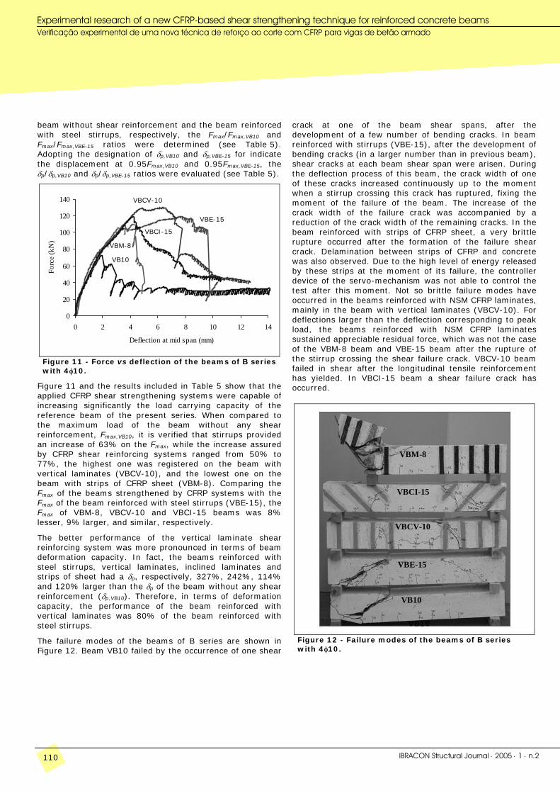
3.2 B series 3.2.1 Beams with 4φ10 For the beams VB10, VBE-15, VBM-8, VBCV-10 and VBCI-15, the relationship between the force and the deflection at beam mid span is depicted in Figure 11. For each beam, Table 5 includes the registered values of the maximum load (Fmax). Adopting the designation of Fmax,VB10 and Fmax,VBE-15 for referring the maximum load carrying capacity of the
12
Experimental research of a new CFRP-based shear strengthening technique for reinforced concrete beams Verificação experimental de uma nova técnica de reforço ao corte com CFRP para vigas de betão armado
110 IBRACON Structural Journal ⋅ 2005 ⋅ 1 ⋅ n.2
beam without shear reinforcement and the beam reinforced with steel stirrups, respectively, the Fmax/Fmax,VB10 and Fmax/Fmax,VBE-15 ratios were determined (see Table 5). Adopting the designation of δp,VB10 and δp,VBE-15 for indicate the displacement at 0.95Fmax,VB10 and 0.95Fmax,VBE-15, the δp/δp,VB10 and δp/δp,VBE-15 ratios were evaluated (see Table 5).
0
20
40
60
80
100
120
140
0 2 4 6 8 10 12 14
Deflection at mid span (mm)
Forc
e (k
N)
Figure 11 - Force vs deflection of the beams of B series with 4φ10.
Figure 11 and the results included in Table 5 show that the applied CFRP shear strengthening systems were capable of increasing significantly the load carrying capacity of the reference beam of the present series. When compared to the maximum load of the beam without any shear reinforcement, Fmax,VB10, it is verified that stirrups provided an increase of 63% on the Fmax, while the increase assured by CFRP shear reinforcing systems ranged from 50% to 77%, the highest one was registered on the beam with vertical laminates (VBCV-10), and the lowest one on the beam with strips of CFRP sheet (VBM-8). Comparing the Fmax of the beams strengthened by CFRP systems with the Fmax of the beam reinforced with steel stirrups (VBE-15), the Fmax of VBM-8, VBCV-10 and VBCI-15 beams was 8% lesser, 9% larger, and similar, respectively.
The better performance of the vertical laminate shear reinforcing system was more pronounced in terms of beam deformation capacity. In fact, the beams reinforced with steel stirrups, vertical laminates, inclined laminates and strips of sheet had a δp, respectively, 327%, 242%, 114% and 120% larger than the δp of the beam without any shear reinforcement (δp,VB10). Therefore, in terms of deformation capacity, the performance of the beam reinforced with vertical laminates was 80% of the beam reinforced with steel stirrups.
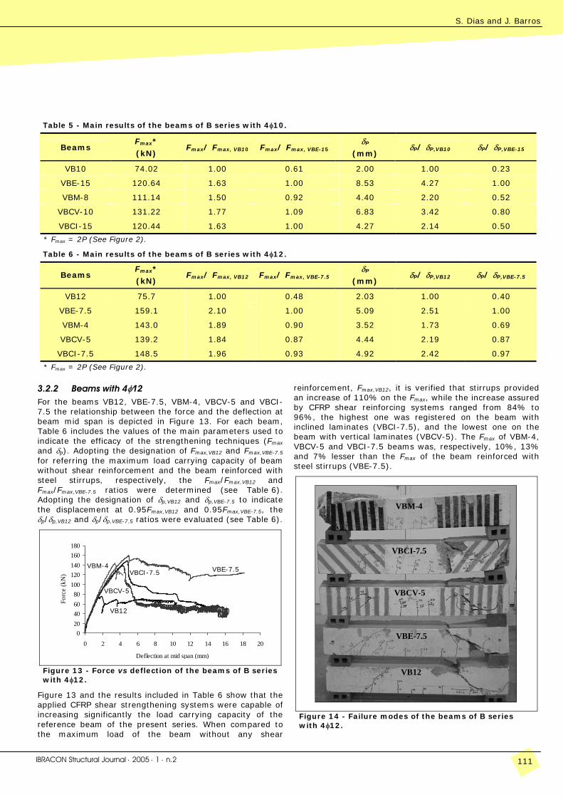
The failure modes of the beams of B series are shown in Figure 12. Beam VB10 failed by the occurrence of one shear
crack at one of the beam shear spans, after the development of a few number of bending cracks. In beam reinforced with stirrups (VBE-15), after the development of bending cracks (in a larger number than in previous beam), shear cracks at each beam shear span were arisen. During the deflection process of this beam, the crack width of one of these cracks increased continuously up to the moment when a stirrup crossing this crack has ruptured, fixing the moment of the failure of the beam. The increase of the crack width of the failure crack was accompanied by a reduction of the crack width of the remaining cracks. In the beam reinforced with strips of CFRP sheet, a very brittle rupture occurred after the formation of the failure shear crack. Delamination between strips of CFRP and concrete was also observed. Due to the high level of energy released by these strips at the moment of its failure, the controller device of the servo-mechanism was not able to control the test after this moment. Not so brittle failure modes have occurred in the beams reinforced with NSM CFRP laminates, mainly in the beam with vertical laminates (VBCV-10). For deflections larger than the deflection corresponding to peak load, the beams reinforced with NSM CFRP laminates sustained appreciable residual force, which was not the case of the VBM-8 beam and VBE-15 beam after the rupture of the stirrup crossing the shear failure crack. VBCV-10 beam failed in shear after the longitudinal tensile reinforcement has yielded. In VBCI-15 beam a shear failure crack has occurred.
VB10
VBE-15
VBCI-15
VBCV-10
VBM-8
Figure 12 - Failure modes of the beams of B series with 4φ10.
VB10
VBM-8
VBCV-10
VBE-15
VBCI-15
VB10
S. Dias and J. Barros
IBRACON Structural Journal ⋅ 2005 ⋅ 1 ⋅ n.2 111
Table 5 - Main results of the beams of B series with 4φ10.
Beams Fmax*
(kN) Fmax/ Fmax, VB10 Fmax/ Fmax, VBE-15
δP
(mm) δP/ δP,VB10 δP/ δP,VBE-15
VB10 74.02 1.00 0.61 2.00 1.00 0.23
VBE-15 120.64 1.63 1.00 8.53 4.27 1.00
VBM-8 111.14 1.50 0.92 4.40 2.20 0.52
VBCV-10 131.22 1.77 1.09 6.83 3.42 0.80
VBCI-15 120.44 1.63 1.00 4.27 2.14 0.50
* Fmax = 2P (See Figure 2).
Table 6 - Main results of the beams of B series with 4φ12.
Beams Fmax*
(kN) Fmax/ Fmax, VB12 Fmax/ Fmax, VBE-7.5
δP
(mm) δP/ δP,VB12 δP/ δP,VBE-7.5
VB12 75.7 1.00 0.48 2.03 1.00 0.40
VBE-7.5 159.1 2.10 1.00 5.09 2.51 1.00
VBM-4 143.0 1.89 0.90 3.52 1.73 0.69
VBCV-5 139.2 1.84 0.87 4.44 2.19 0.87
VBCI-7.5 148.5 1.96 0.93 4.92 2.42 0.97
* Fmax = 2P (See Figure 2).
3.2.2 Beams with 4φ12 For the beams VB12, VBE-7.5, VBM-4, VBCV-5 and VBCI-7.5 the relationship between the force and the deflection at beam mid span is depicted in Figure 13. For each beam, Table 6 includes the values of the main parameters used to indicate the efficacy of the strengthening techniques (Fmax and δp). Adopting the designation of Fmax,VB12 and Fmax,VBE-7.5 for referring the maximum load carrying capacity of beam without shear reinforcement and the beam reinforced with steel stirrups, respectively, the Fmax/Fmax,VB12 and Fmax/Fmax,VBE-7.5 ratios were determined (see Table 6). Adopting the designation of δp,VB12 and δp,VBE-7.5 to indicate the displacement at 0.95Fmax,VB12 and 0.95Fmax,VBE-7.5, the δp/δp,VB12 and δp/δp,VBE-7.5 ratios were evaluated (see Table 6).
020406080
100120140160180
0 2 4 6 8 10 12 14 16 18 20
Deflection at mid span (mm)
Forc
e (k
N)
Figure 13 - Force vs deflection of the beams of B series with 4φ12.
Figure 13 and the results included in Table 6 show that the applied CFRP shear strengthening systems were capable of increasing significantly the load carrying capacity of the reference beam of the present series. When compared to the maximum load of the beam without any shear
reinforcement, Fmax,VB12, it is verified that stirrups provided an increase of 110% on the Fmax, while the increase assured by CFRP shear reinforcing systems ranged from 84% to 96%, the highest one was registered on the beam with inclined laminates (VBCI-7.5), and the lowest one on the beam with vertical laminates (VBCV-5). The Fmax of VBM-4, VBCV-5 and VBCI-7.5 beams was, respectively, 10%, 13% and 7% lesser than the Fmax of the beam reinforced with steel stirrups (VBE-7.5).
VB12
VBE-7.5
VBCI-7.5
VBCV-5
VBM-4
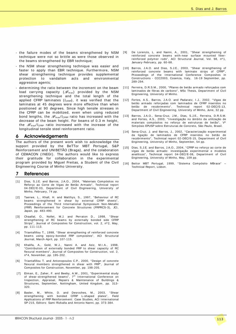
Figure 14 - Failure modes of the beams of B series with 4φ12.
VBM-4
VBCV-5
VBE-7.5 VBCI-7.5
VB12
12
Experimental research of a new CFRP-based shear strengthening technique for reinforced concrete beams Verificação experimental de uma nova técnica de reforço ao corte com CFRP para vigas de betão armado
112 IBRACON Structural Journal ⋅ 2005 ⋅ 1 ⋅ n.2
The better performance of the inclined laminate shear reinforcing system was more pronounced in terms of beam deformation capacity. In fact, the beams reinforced with steel stirrups, inclined laminates, vertical laminates and strips of sheet had a δp, respectively, 151%, 142%, 119% and 73% larger than the δp of the beam without any shear reinforcement (δp,VB12). Therefore, in terms of deformation capacity, the performance of the beam reinforced with inclined laminates was 97% of the beam reinforced with steel stirrups.
Figure 14 includes the photos of the beams after have been tested. A representation of the failure modes is also depicted. In VB12 unreinforced beam, after the development of flexural cracks, two shear cracks arisen, one in each beam shear spans. This beam failed in shear. In beam reinforced with steel stirrups (VBE-7.5), after the development of flexural cracks (in a larger number than in the previous beam), shear cracks at each beam shear span were formed. During the deflection process of this beam, the crack width of one of these cracks increased continuously up to the moment when a stirrup crossing this crack has ruptured, fixing the moment of the failure of this beam. The increase of the crack width of the failure crack was accompanied by a reduction of the crack width of the remaining cracks. The beam reinforced with strips of CFRP sheet (VBM-4) failed abruptly. The strips crossing the shear failure crack have peeled off just after the formation of this crack. Not so brittle failure modes have occurred in the beams reinforced with NSM CFRP laminates. In VBCV-5 beam a shear failure crack has formed. During the opening process of this crack, the shorter bond length of the CFRP laminate crossing this crack has slid. In VBCI-7.5 beam a shear failure crack has occurred.
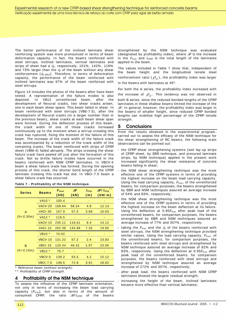
Table 7 - Profitability of the NSM technique.
Series Beams Fmax
(kN) ∆F
(kN) lcfrp (m)
∆F/lcfrp**
(kN/m)
VA10 * 100.4 - - -
VACV-20 158.64 58.24 4.8 12.13
VACI-30 157.9 57.5 3.68 15.63
VA12 * 116.5 - - -
VACV-10 235.11 118.61 8.4 14.12
A (h=0.30m)
VACI-15 262.38 145.88 7.35 19.85
VB10 * 74.02 - - -
VBCV-10 131.22 57.2 2.4 23.83
VBCI-15 120.44 46.42 1.97 23.56
VB12 * 75.7 - - -
VBCV-5 139.2 63.5 4.2 15.12
B (h=0.15m)
VBCI-7.5 148.5 72.8 3.91 18.62
* Reference beam (without strength); ** Profitability of CFRP strength.
4 Profitability of the NSM technique To assess the influence of the CFRP laminate orientation, not only in terms of increasing the beam load carrying capacity (Fmax), but also in terms of the amount of consumed CFRP, the ratio ∆F/lCFRP of the beams
strengthened by the NSM technique was evaluated (designated by profitability index), where ∆F is the increase in the Fmax and lCFRP is the total length of the laminates applied in the beam.
The values included in Table 7 show that, independent of the beam height and the longitudinal tensile steel
reinforcement ratio ( slρ ), the profitability index was larger
in the beams with laminates at 45º.
For both the A series, the profitability index increased with
the increase of slρ . This tendency was not observed in
both B series, since the reduced bonded lengths of the CFRP laminates in these shallow beams limited the increase of the ∆F. In general, however, the profitability index was larger in the beams of smaller height, since reduced CFRP bonded lengths can mobilize high percentage of the CFRP tensile strength.
5 Conclusions From the results obtained in the experimental program, carried out to assess the efficacy of the NSM technique for the shear strengthening of RC beams, the following main observations can be pointed out:
- the CFRP shear strengthening systems (wet lay-up strips of CFRP sheet, by EBR technique, and precured laminate strips, by NSM technique) applied in the present work increased significantly the shear resistance of concrete beams failing in shear;
- the NSM shear strengthening technique was the most effective one of the CFRP systems in terms of providing the highest increase on the beam load carrying capacity. Using the load carrying capacity, Fmax, of the unreinforced beams, for comparison purposes, the beams strengthened by EBR and NSM techniques assured an average increase of 54% and 83%, respectively;
- the NSM shear strengthening technique was the most effective one of the CFRP systems in terms of providing the highest increase on the beam deflection at its failure. Using the deflection at 0.95Fmax after peak load of the unreinforced beams, for comparison purposes, the beams strengthened by EBR and NSM techniques assured an average increase of 77% and 307%, respectively;
- taking the Fmax and the δp of the beams reinforced with steel stirrups, the NSM strengthening technique provided similar values. Using the load carrying capacity, Fmax, of the unreinforced beams, for comparison purposes, the beams reinforced with steel stirrups and strengthened by NSM technique assured an average increase of 82% and 83%, respectively. Using the deflection at 0.95Fmax after peak load of the unreinforced beams, for comparison purposes, the beams reinforced with steel stirrups and strengthened by NSM technique assured an average increase of 272% and 307%, respectively;
- after peak load, the beams reinforced with NSM CFRP laminates showed the largest residual strength;
- increasing the height of the beam, inclined laminates became more effective than vertical laminates;
S. Dias and J. Barros
IBRACON Structural Journal ⋅ 2005 ⋅ 1 ⋅ n.2 113
- the failure modes of the beams strengthened by NSM technique were not so brittle as were those observed in the beams strengthened by EBR technique;
- the NSM shear strengthening technique was easier and faster to apply than EBR technique. Furthermore, NSM shear strengthening technique provides supplemental protection to vandalism acts and environmental aggressive agents;
- determining the ratio between the increment on the beam load carrying capacity (∆Fmax) provided by the NSM strengthening technique and the total length of the applied CFRP laminates (lCFRP), it was verified that the laminates at 45 degrees were more effective than when positioned at 90 degrees. Since high tensile stresses in the CFRP can be mobilized, even when using reduced bond lengths, the ∆Fmax/lCFRP ratio has increased with the decrease of the beam height. For beams of 0.3 m height, the ∆Fmax/lCFRP ratio increased with the increase of the longitudinal tensile steel reinforcement ratio.
6 Acknowledgements The authors of the present work wish to acknowledge the support provided by the BeTTor MBT Portugal, S&P Reinforcement and UNIBETÃO (Braga), and the colaboration of CEMACON (INEGI). The authors would like to express their gratitude for collaboration in the experimental program provided by Miguel Freitas, a Student of the Civil Engineering Course of Minho University.
7 References [1] Dias, S.J.E. and Barros, J.A.O., 2004, “Materiais Compósitos no
Reforço ao Corte de Vigas de Betão Armado”, Technical report 04-DEC/E-03, Department of Civil Engineering, University of Minho, February, 74 pp.
[2] Taerwe, L., Khall, H. and Matthys, S., 1997, “Behaviour of RC beams strengthened in shear by external CFRP sheets”, Proceedings of the Third International Symposium Non-Metallic (FRP) Reinforcement for Concrete Structures (FRPRCS-3), JCI, Japan, pp. 483-490.
[3] Chaallal, O., Nollet, M.J. and Perraton D., 1998, “Shear strengthening of RC beams by externally bonded side CFRP Strips”, Journal of Composites for Construction, vol. 2, nº2, May, pp. 111-113.
[4] Triantafillou T., 1998, “Shear strengthening of reinforced concrete beams using epoxy-bonded FRP composites”, ACI Structural Journal, March-April, pp. 107-115.
[5] Khalifa, A., Gold, W.J., Nanni A. and Aziz, M.I.A., 1998, “Contribution of externally bonded FRP to shear capacity of RC flexural members”, Journal of Composites for Construction, vol. 2, nº4, November, pp. 195-202.
[6] Triantafillou T. and Antonopoulos C.P., 2000, “Design of concrete flexural members strengthened in shear with FRP”, Journal of Composites for Construction, November, pp. 198-205.
[7] Etman, E., Zaher, F. and Beeby, A.W., 2001, “Experimental study of shear-strengthened beams”, 7th International Conference on Inspection, Appraisal, Repairs & Maintenance of Buildings & Structures, September, Nottingham, United Kingdom, pp. 313-320.
[8] Basler, M., White, D. and Desroches, M., 2003, “Shear strengthening with bonded CFRP L-shaped plates”, Field Applications of FRP Reinforcement: Case Studies, ACI International SP-215, Editors: Sami Rizkalla and Antonio Nanni, pp. 373-384.
[9] De Lorenzis, L. and Nanni, A., 2001, “Shear strengthening of reinforced concrete beams with-near surface mounted fiber-reinforced polymer rods”, ACI Structural Journal, Vol. 98, nº1, January-February, pp. 60-68.
[10] Barros, J.A.O. and Dias, S.J.E., 2003, “Shear strengthening of reinforced concrete beams with laminate strips of CFRP”, Proceedings of the International Conference Composites in Constructions - CCC2003, Cosenza, Italy, 16-19 September, pp. 289-294.
[11] Ferreira, D.R.S.M., 2000, “Pilares de betão armado reforçados com laminados de fibras de carbono”, MSc Thesis, Department of Civil Engineering, University of Minho.
[12] Fortes, A.S., Barros, J.A.O. and Padaratz, I.J., 2002, “Vigas de betão armado reforçadas com laminados de CFRP inseridos no betão de recobrimento”, Technical report 02-DEC/E-13, Department of Civil Engineering, University of Minho, June, 32 pp.
[13] Barros, J.A.O., Sena-Cruz, J.M., Dias, S.J.E., Ferreira, D.R.S.M. and Fortes, A.S., 2003, “Investigação no âmbito da utilização de materiais compósitos no reforço de estruturas de betão”, Vº Simpósio EPUSP sobre Estruturas de Concreto, São Paulo, Brasil.
[14] Sena-Cruz, J. and Barros, J., 2002, “Caracterização experimental da ligação de laminados de CFRP inseridos no betão de recobrimento”, Technical report 02-DEC/E-15, Department of Civil Engineering, University of Minho, September, 54 pp.
[15] Dias, S.J.E. and Barros, J.A.O., 2004, “CFRP no reforço ao corte de vigas de betão armado: investigação experimental e modelos analíticos”, Technical report 04-DEC/E-08, Department of Civil Engineering, University of Minho, May, 109 pp.
[16] Bettor MBT Portugal, 1999, “Sistema Compósito MBrace” – Technical Report, Lisbon.
12
Experimental research of a new CFRP-based shear strengthening technique for reinforced concrete beams Verificação experimental de uma nova técnica de reforço ao corte com CFRP para vigas de betão armado
114 IBRACON Structural Journal ⋅ 2005 ⋅ 1 ⋅ n.2