Embed Size (px)
Citation preview
DAAAM INTERNATIONAL SCIENTIFIC BOOK 2012 pp. 255-266 CHAPTER 22
EXPERIMENTAL MEASUREMENT OF CUTTING
FORCES IN THE TURNING TECHNOLOGY
DUBOVSKA, R.; MAJERIK, J. & BASKA, I.
Abstract: The main aim of this scientific study is to assess the contribution of surface layers of alloy AlCu3MgMnPb by determining the experimental measurement of cutting forces in the turning technology with the coated carbide cutting insert. This experimental study is a continuation of the solutions of grant VEGA no. 1/9428/02
titled “The technological heredity of the machined surfaces - surface integrity”. The first chapter of this paper discussed about the possibilities and technological
challenges in turning of Al-alloys. The second chapter discusses about technological characteristics of cutting process and cutting forces. In the third and fourth chapter is described the measurement of cutting forces in turning by Kistler dynamometer. This paper, together with published results is a basis that will enable optimizing the quality of turning process, automotive parts of their dominant functional areas. key words: cutting forces, Measurement, dynamometer KISTLER, machining process, machined surfaces
Authors´ data: Univ.Prof. Dipl.-Ing. Dr. Sc. Dubovska, R[ozmarina]; Dipl.-Ing.
PhD. Majerik, J[ozef]; Dipl.-Ing. PhD. Baska, I[van], University of Hradec
Kralove, Namesti Svobody 301, 500 03, Hradec Kralove, Czech republic,
[email protected], [email protected], [email protected]
This Publication has to be referred as: Dubovska, R[ozmarina]; Majerik, J[ozef] &
Baska, I[van] (2012). Experimental Measurement of Cutting Forces in the Turning
Technology, Chapter 22 in DAAAM International Scientific Book 2012, pp. 255-
266, B. Katalinic (Ed.), Published by DAAAM International, ISBN 978-3-901509-
86-5, ISSN 1726-9687, Vienna, Austria
DOI: 10.2507/daaam.scibook.2012.22
255
Dubovska, R.; Majerik, J. & Baska, I.: Experimental Measurement of Cutting Forc…
1. Introduction
The main aim of this experimental paper is to study, analyze and realize the
experimental measurement of cutting forces at turning of rotational parts made from
aluminium alloy AlCu3MgMnPb. This measurement was successively analyzed and
experimentally verified on selected sample materials (in experimental measuring of
the cutting forces during the turning process of parts and measured and results
designated with the piezoelectric KISTLER dynamometer). Experiment team of
authors is limited to the measurement of cutting forces in turning aluminum alloy as
the material used in the automotive industry. Is a partial solution of the project
dealing with the production of dominant functional areas in a university research
cooperation and networking of manufacturing practices to the requirements of the
industry to improve the quality of the machining process, and operating
characteristics of the final product.
Application materials for the cutting tools are defined by their physical,
chemical, thermal and mechanical properties (Humar, 2008). The term does not
include only a machining process or a description of how to make machinery
component removal of excess material, but also clarifying and explaining existing
factors and phenomena in the machining process. Machining is therefore also its
scientific, not only practical part. The theory provides hypotheses that are
experimentally verified and verification of hypothesis becomes a theory validation.
In theory aside the agreed convention for marking and cutting action of cutting
forces, as well as forces that are associated with an internal resistance of the cutting
material (Piska & Forejt, 2006).
One of the management strategies for business success in the market is a
strategy of continuous improvement of production quality through the
implementation of quality management and continuous improvement. Improving
product quality then affects not only the production processes, but also post-
production activities (Jambor, 2010).
One of the main process engineering company is a manufacturing process that
can be improved, including through implementation of new technologies and
production processes in turning to activities related to experimental measurements of
cutting forces in turning technology.
Cutting force is tied to the relative movement between tool and workpiece. As
relates to the resistance to motion, it cannot be regarded as a constant variable in time
(Beno, 1999).
Research on cutting forces in machining of metals is not only practical but also
theoretical importance. Theoretical knowledge of the cutting forces to refine theories
about the cutting process. In practice, again knowledge of the importance of cutting
forces for design tools, the selection of cutting conditions, calculations and design of
machine tools etc. (Neslusan, 2009).
Links between technology and machining surface quality, building on their
functionality in the future must cover the entire technological world, they show ways
to deal with ever-increasing demands on product quality and offered use of reserves
resulting (Batora & Vasilko, 2000).
256
DAAAM INTERNATIONAL SCIENTIFIC BOOK 2012 pp. 255-266 CHAPTER 22
2. Technological characteristics of machining process
The cutting process is characterized by a number of technological parameters.
The basic characteristics should be calculated geometric and strength values, work
and cutting power, heat and temperature of cutting and vibration (shaking),
machining system (Majerik & Sandora, 2012).
Geometrical variables, which generally characterize the cutting process are:
kinematic variables, feed, cutting edge, shot, cross section (chips) and machining
performance (Kocman, 2004).
The kinematic parameters characterize the cutting process: the main cutting
motion, cutting speed, feed movement and its direction, feed rate, cutting movement
and its direction, the cutting speed of movement (Sandora et. al, 2006).
The longitudinal turning cylindrical surface is generally valid (1), (2), (3).
Cutting speed - 1000
nDvc
(m·min-1
) (1)
Feed rate - 1000
nfv f
(m·min
-1) (2)
Speed of cutting process - 22
fce vvv (m·min-1
) (3)
3. Cutting forces in turning technology
The total cutting force induced by the action of the cutting tool to the
workpiece is called the symbol F. For the analysis of power formula of the cutting
process, the resulting cutting force F breaks down into relevant components. During
the act of turning the workpiece cutting force F, which is the vector can be separated
into individual components (Vasilko et. al, 2006).
The active force F is determined by the projection of the total cutting force F to
the working side of the plane shift Pfe. Passive force Fp is also a component of the
total cutting force F, perpendicular to the plane Pfe work side and the direction of the
resultant cutting motion. Workforce Fe expressed the general orthogonal cutting
forces in the direction of cutting motion and is defined in the working plane side Pfe.
The cutting force Fc is a component of the total cutting force F identified the direction
orthogonal to the main motion, i.e. vector in the direction of cutting speed vc. It is the
main component of cutting force. To determine the cutting force Fc must know the
specific cutting force (resistance) kc, which is defined as the ratio of cutting forces Ff
and nominal cross sectional area (chip) AD.
D
c
cA
Fk ( N·mm
-2 = MPa) (4)
257
Dubovska, R.; Majerik, J. & Baska, I.: Experimental Measurement of Cutting Forc…
Component of the total cutting force F, defined in operational terms relating to the
direction of the adjusting movement Ft, is given by the projection of the total force F
in the direction of the adjusting movement.
3.1 Calculation of components of cutting forces
Cutting force components were recorded in the computer considering the
scheme of experimental measurement (Steiningerova & Majerik, 2010).The process
component operates as the resultant force F, which is the sum of the elemental forces.
It is decomposed into the three components (Dubovska et al., 2011)
For turning cylindrical surface components, see here the following empirical
dependences (5), (6), (7).
cFcF
c
yx
pFc faCF (N) (5)
pFpF
p
yx
pFp faCF (N) (6)
fFfF
f
yx
pFf faCF (N) (7)
The known size of the specific cutting force (resistance) kc is possible to calculate the
cutting force Fc of the formula (8).
fakbhkAkF pcDDcDcc (N) (8)
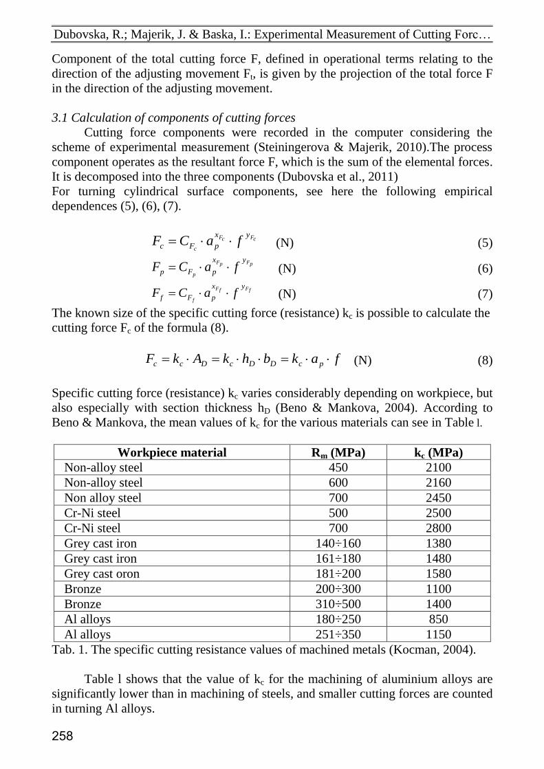
Specific cutting force (resistance) kc varies considerably depending on workpiece, but
also especially with section thickness hD (Beno & Mankova, 2004). According to
Beno & Mankova, the mean values of kc for the various materials can see in Table l.
Workpiece material Rm (MPa) kc (MPa)
Non-alloy steel 450 2100
Non-alloy steel 600 2160
Non alloy steel 700 2450
Cr-Ni steel 500 2500
Cr-Ni steel 700 2800
Grey cast iron 140÷160 1380
Grey cast iron 161÷180 1480
Grey cast oron 181÷200 1580
Bronze 200÷300 1100
Bronze 310÷500 1400
Al alloys 180÷250 850
Al alloys 251÷350 1150
Tab. 1. The specific cutting resistance values of machined metals (Kocman, 2004).
Table l shows that the value of kc for the machining of aluminium alloys are
significantly lower than in machining of steels, and smaller cutting forces are counted
in turning Al alloys.
258
DAAAM INTERNATIONAL SCIENTIFIC BOOK 2012 pp. 255-266 CHAPTER 22
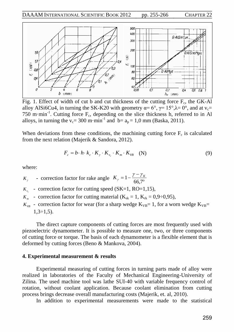
Fig. 1. Effect of width of cut b and cut thickness of the cutting force Fc, the GK-Al
alloy AlSi6Cu4, in turning the SK-K20 with geometry α= 6°, γ= 15°,λ= 0°, and at vc=
750 m·min-1
. Cutting force Fc, depending on the slice thickness h, referred to in Al
alloys, in turning the vc= 300 m·min-1
and b= ap = 1,0 mm (Baska, 2011).
When deviations from these conditions, the machining cutting force Fc is calculated
from the next relation (Majerik & Sandora, 2012).
VBmvcc KKKKkhbFc
(N) (9)
where:
K - correction factor for rake angle
7,661 KK
cvK - correction factor for cutting speed (SK=1, RO=1,15),
mK - correction factor for cutting material (Ksk = 1, Krk = 0,9÷0,95),
VBK - correction factor for wear (for a sharp wedge KVB= 1, for a worn wedge KVB=
1,3÷1,5).
The direct capture components of cutting forces are most frequently used with
piezoelectric dynamometer. It is possible to measure one, two, or three components
of cutting force or torque. The basis of each dynamometer is a flexible element that is
deformed by cutting forces (Beno & Mankova, 2004).
4. Experimental measurement & results
Experimental measuring of cutting forces in turning parts made of alloy were
realized in laboratories of the Faculty of Mechanical Engineering-University of
Zilina. The used machine tool was lathe SUI-40 with variable frequency control of
rotation, without coolant application. Because coolant elimination from cutting
process brings decrease overall manufacturing costs (Majerik, et. al, 2010).
In addition to experimental measurements were made to the statistical
259
Dubovska, R.; Majerik, J. & Baska, I.: Experimental Measurement of Cutting Forc…
treatment of the cutting force Fc depending on the depth of cut and feed rate, as well
as the dependence T = f (vc), in turning Al alloys in the manufacturing and evaluate it
using the least squares method (Neslusan et al, 2007).
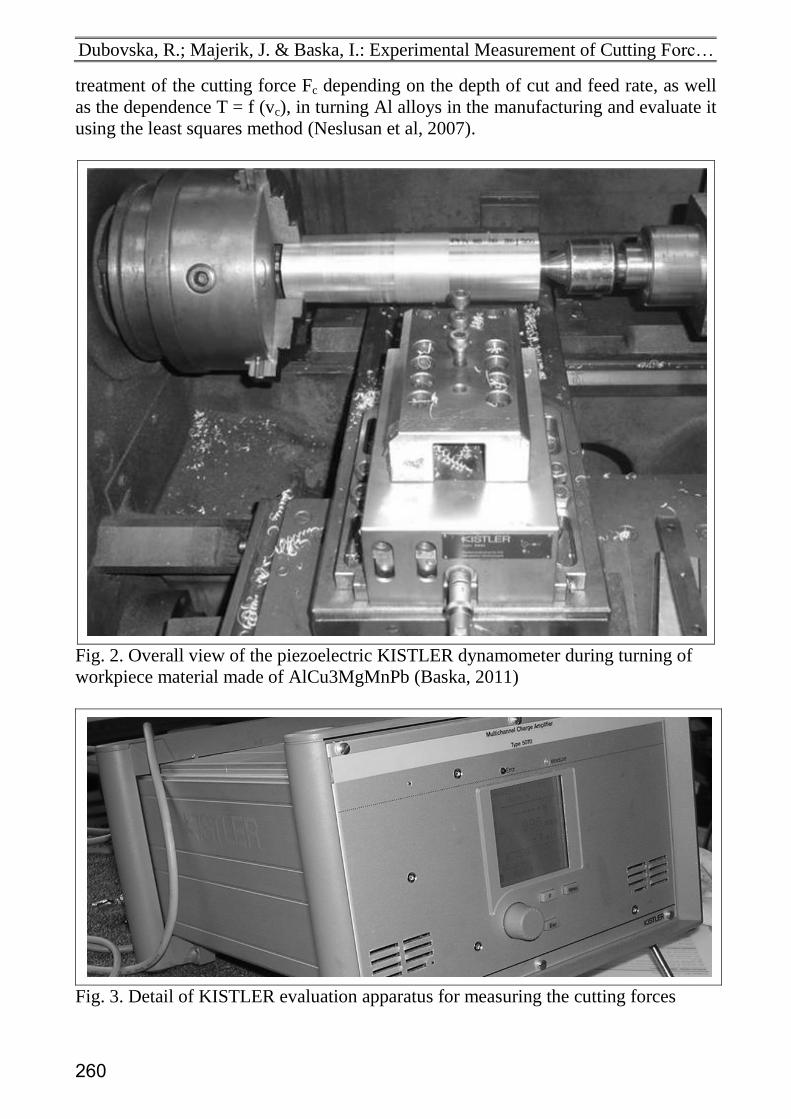
Fig. 2. Overall view of the piezoelectric KISTLER dynamometer during turning of
workpiece material made of AlCu3MgMnPb (Baska, 2011)
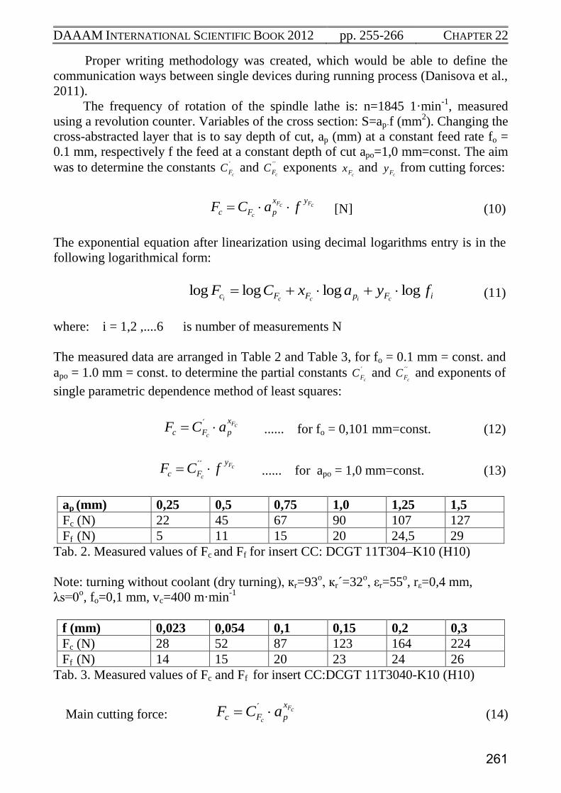
Fig. 3. Detail of KISTLER evaluation apparatus for measuring the cutting forces
260
DAAAM INTERNATIONAL SCIENTIFIC BOOK 2012 pp. 255-266 CHAPTER 22
Proper writing methodology was created, which would be able to define the
communication ways between single devices during running process (Danisova et al.,
2011).
The frequency of rotation of the spindle lathe is: n=1845 1·min-1
, measured
using a revolution counter. Variables of the cross section: S=ap·f (mm2). Changing the
cross-abstracted layer that is to say depth of cut, ap (mm) at a constant feed rate fo =
0.1 mm, respectively f the feed at a constant depth of cut apo=1,0 mm=const. The aim
was to determine the constants ´
cFC and ´´
cFC exponents cFx and
cFy from cutting forces:
cFcF
c
yx
pFc faCF [N] (10)
The exponential equation after linearization using decimal logarithms entry is in the
following logarithmical form:
iFpFFc fyaxCFcicci
loglogloglog (11)
where: i = 1,2 ,....6 is number of measurements N
The measured data are arranged in Table 2 and Table 3, for fo = 0.1 mm = const. and
apo = 1.0 mm = const. to determine the partial constants
´
cFC and ´´
cFC and exponents of
single parametric dependence method of least squares:
cF
c
x
pFc aCF ´ ...... for fo = 0,101 mm=const. (12)
cF
c
y
Fc fCF ´́
...... for apo = 1,0 mm=const. (13)
ap (mm) 0,25 0,5 0,75 1,0 1,25 1,5
Fc (N) 22 45 67 90 107 127
Ff (N) 5 11 15 20 24,5 29
Tab. 2. Measured values of Fc and Ff for insert CC: DCGT 11T304–K10 (H10)
Note: turning without coolant (dry turning), кr=93o, кr´=32
o, εr=55
o, rε=0,4 mm,
λs=0o, fo=0,1 mm, vc=400 m·min
-1
f (mm) 0,023 0,054 0,1 0,15 0,2 0,3
Fc (N) 28 52 87 123 164 224
Ff (N) 14 15 20 23 24 26
Tab. 3. Measured values of Fc and Ff for insert CC:DCGT 11T3040-K10 (H10)
Main cutting force: cF
c
x
pFc aCF ´ (14)
261
Dubovska, R.; Majerik, J. & Baska, I.: Experimental Measurement of Cutting Forc…
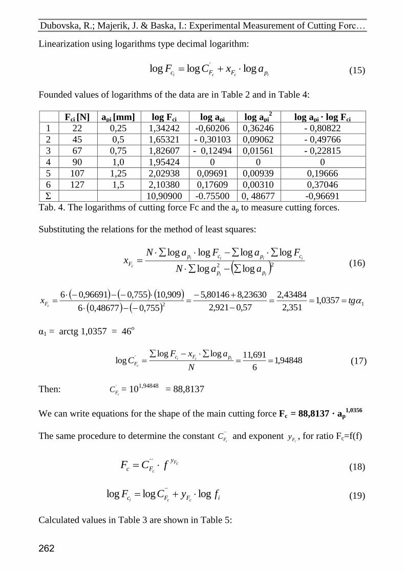
Linearization using logarithms type decimal logarithm:
icci pFFc axCF logloglog ´ (15)
Founded values of logarithms of the data are in Table 2 and in Table 4:
Fci [N] api [mm] log Fci log api log api2 log api · log Fci
1 22 0,25 1,34242 -0,60206 0,36246 - 0,80822
2 45 0,5 1,65321 - 0,30103 0,09062 - 0,49766
3 67 0,75 1,82607 - 0,12494 0,01561 - 0,22815
4 90 1,0 1,95424 0 0 0
5 107 1,25 2,02938 0,09691 0,00939 0,19666
6 127 1,5 2,10380 0,17609 0,00310 0,37046
Σ 10,90900 -0.75500 0, 48677 -0,96691
Tab. 4. The logarithms of cutting force Fc and the ap to measure cutting forces.
Substituting the relations for the method of least squares:
22 loglog
loglogloglog
ii
iiii
c
pp
cpcp
FaaN
FaFaNx
(16)
12
0357,1351,2
43484,2
57,0921,2
23630,880146,5
755,048677,06
909,10755,096691,06tgx
cF
α1 = arctg 1,0357 = 46o
94848,16
691,11logloglog ´
N
axFC ici
c
pFc
F (17)
Then: ´
cFC = 101,94848
= 88,8137
We can write equations for the shape of the main cutting force Fc = 88,8137 · ap1,0356
The same procedure to determine the constant ´´
cFC and exponent
cFy , for ratio Fc=f(f)
cF
c
y
Fc fCF ´́ (18)
iFFc fyCFcci
logloglog ´́ (19)
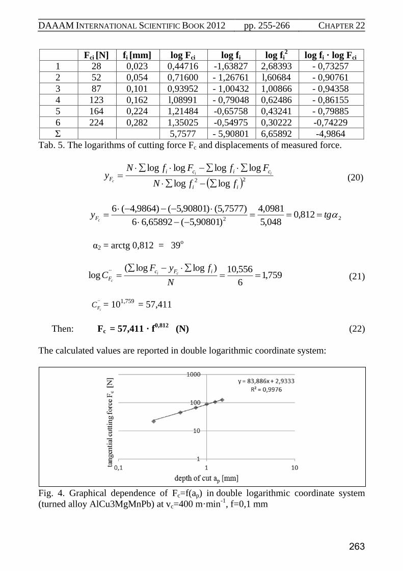
Calculated values in Table 3 are shown in Table 5:
262
DAAAM INTERNATIONAL SCIENTIFIC BOOK 2012 pp. 255-266 CHAPTER 22
Fci [N] fi [mm] log Fci log fi log fi2 log fi · log Fci
1 28 0,023 0,44716 -1,63827 2,68393 - 0,73257
2 52 0,054 0,71600 - 1,26761 l,60684 - 0,90761
3 87 0,101 0,93952 - 1,00432 1,00866 - 0,94358
4 123 0,162 l,08991 - 0,79048 0,62486 - 0,86155
5 164 0,224 1,21484 -0,65758 0,43241 - 0,79885
6 224 0,282 1,35025 -0,54975 0,30222 -0,74229
Σ 5,7577 - 5,90801 6,65892 -4,9864
Tab. 5. The logarithms of cutting force Fc and displacements of measured force.
22 loglog
loglogloglog
ii
cici
FffN
FfFfNy ii
c
(20)
22812,0
048,5
0981,4
)90801,5(65892,66
)7577,5()90801,5()9864,4(6tgy
cF
α2 = arctg 0,812 = 39o
759,16
556,10)loglog(log ´́
N
fyFC
iFc
Fci
c (21)
´´
cFC = 101,759
= 57,411
Then: Fc = 57,411 · f0,812
(N) (22)
The calculated values are reported in double logarithmic coordinate system:
Fig. 4. Graphical dependence of Fc=f(ap) in double logarithmic coordinate system
(turned alloy AlCu3MgMnPb) at vc=400 m·min-1
, f=0,1 mm
263
Dubovska, R.; Majerik, J. & Baska, I.: Experimental Measurement of Cutting Forc…
Fig. 5. Graphical dependence of Fc=f(f) in double logarithmic coordinate system
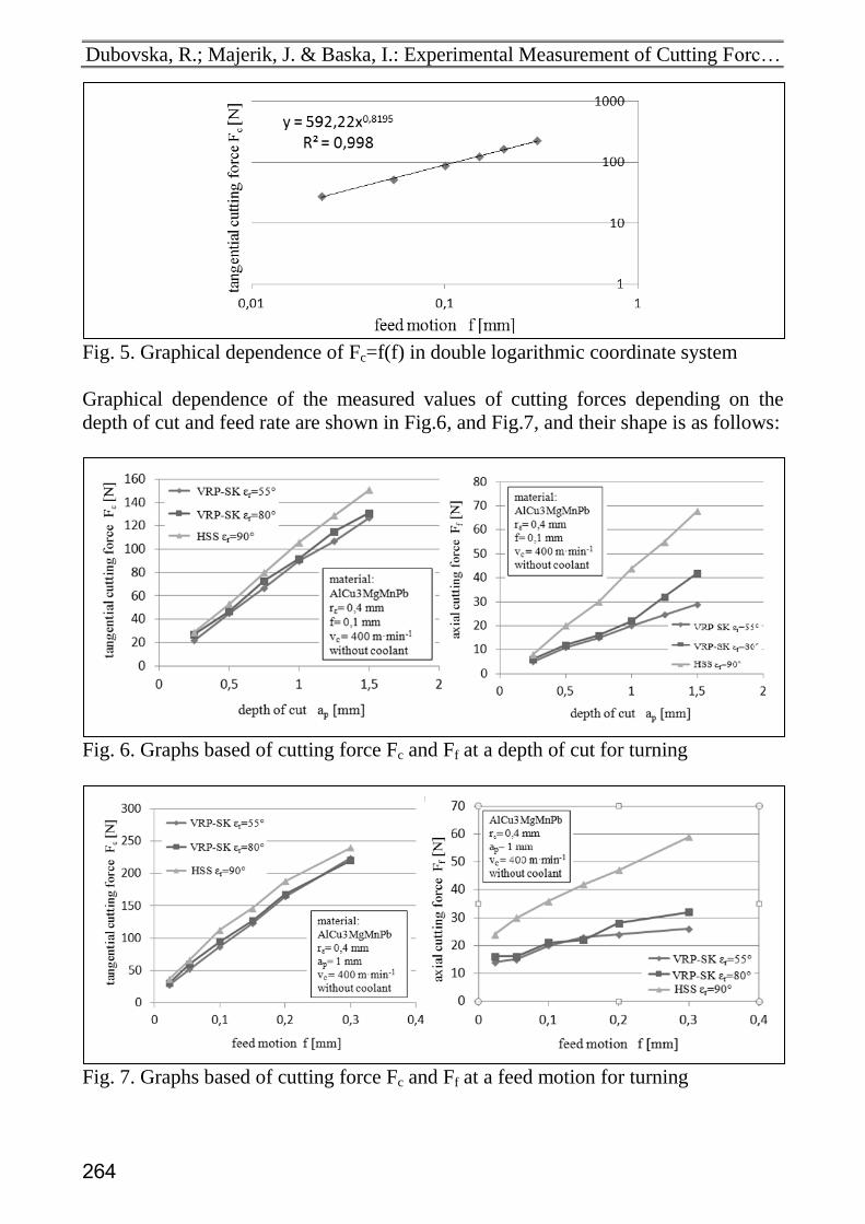
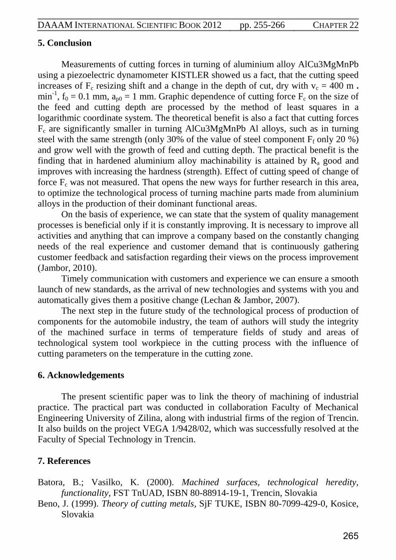
Graphical dependence of the measured values of cutting forces depending on the
depth of cut and feed rate are shown in Fig.6, and Fig.7, and their shape is as follows:
Fig. 6. Graphs based of cutting force Fc and Ff at a depth of cut for turning
Fig. 7. Graphs based of cutting force Fc and Ff at a feed motion for turning
264
DAAAM INTERNATIONAL SCIENTIFIC BOOK 2012 pp. 255-266 CHAPTER 22
5. Conclusion
Measurements of cutting forces in turning of aluminium alloy AlCu3MgMnPb
using a piezoelectric dynamometer KISTLER showed us a fact, that the cutting speed
increases of Fc resizing shift and a change in the depth of cut, dry with vc = 400 m •
min-1
, f0 = 0.1 mm, ap0 = 1 mm. Graphic dependence of cutting force Fc on the size of
the feed and cutting depth are processed by the method of least squares in a
logarithmic coordinate system. The theoretical benefit is also a fact that cutting forces
Fc are significantly smaller in turning AlCu3MgMnPb Al alloys, such as in turning
steel with the same strength (only 30% of the value of steel component Ff only 20 %)
and grow well with the growth of feed and cutting depth. The practical benefit is the
finding that in hardened aluminium alloy machinability is attained by Ra good and
improves with increasing the hardness (strength). Effect of cutting speed of change of
force Fc was not measured. That opens the new ways for further research in this area,
to optimize the technological process of turning machine parts made from aluminium
alloys in the production of their dominant functional areas.
On the basis of experience, we can state that the system of quality management
processes is beneficial only if it is constantly improving. It is necessary to improve all
activities and anything that can improve a company based on the constantly changing
needs of the real experience and customer demand that is continuously gathering
customer feedback and satisfaction regarding their views on the process improvement
(Jambor, 2010).
Timely communication with customers and experience we can ensure a smooth
launch of new standards, as the arrival of new technologies and systems with you and
automatically gives them a positive change (Lechan & Jambor, 2007).
The next step in the future study of the technological process of production of
components for the automobile industry, the team of authors will study the integrity
of the machined surface in terms of temperature fields of study and areas of
technological system tool workpiece in the cutting process with the influence of
cutting parameters on the temperature in the cutting zone.
6. Acknowledgements
The present scientific paper was to link the theory of machining of industrial
practice. The practical part was conducted in collaboration Faculty of Mechanical
Engineering University of Zilina, along with industrial firms of the region of Trencin.
It also builds on the project VEGA 1/9428/02, which was successfully resolved at the
Faculty of Special Technology in Trencin.
7. References
Batora, B.; Vasilko, K. (2000). Machined surfaces, technological heredity,
functionality, FST TnUAD, ISBN 80-88914-19-1, Trencin, Slovakia
Beno, J. (1999). Theory of cutting metals, SjF TUKE, ISBN 80-7099-429-0, Kosice,
Slovakia
265
Dubovska, R.; Majerik, J. & Baska, I.: Experimental Measurement of Cutting Forc…
Beno, J.; Mankova, I. (2004). Technological and material factors of machining, SjF
TUKE, ISBN 80-7099-701-X, Kosice, Slovakia
Baska, I. (2011). Technological problems of machining parts made of aluminium
alloys by turning, Dissertation work FST TnUAD, p.150, Trencin, Slovakia
Danisova, N.; Sebenova, S. & Velisek, K. (2011). Application of seguence diagram
within tool change during machining, Annals of DAAAM for
2011&Proceedings of the 22nd International World Symposium, pp. 0459-
0460, ISSN 1726-9679, ISBN 978-3-901509-70-4, Austria Center Vienna, 23-
26th November 2011, Katalinic, B. (Ed.), Vienna, Austria
Dubovska, R.; Majerik, J. & Chochlikova, H. (2011). Physico-chemical state
Stabilization of high strength steels machined surface, Proceedings in
manufacturing systems, Vol.6, No.4, (2011) p. 75-80, ISSN 2067-9238
Humar, A. (2008). Materials for cutting tools, MM publishing, ISBN 978-80-254-
2250-2, Prague, Czech republic
Jambor, J. (2010). Analysis of the results of audits of quality management system –
sales service of cars, Quality Innovation Prosperity, Vol.14, No. 1-2, ISSN
1335-1745, p.1-8, Trencin, Slovakia
Lechan, P.; Jambor, J. (2007). SEAT Service quality management system,
International scientific conference of Vehicles - New trends in construction and
exploitation automobiles, Slovak University of Agriculture, ISBN 978-80-
8069-942-0, Nitra 2007, Slovakia, p. 119-123
Kocman, K. (2004). Special technology - machining, UST FSI VUT, ISBN 80-214-
2562-8, Brno, Czech republic
Majerik, J.; Dubovska, R. & Baska, I. (2010). Positive and negative theoretical and
technological aspects of dry machining or with coolant application, University
Review – Technology of special production, Vol.4, No.3, (2010) p. 25-29, ISSN
1337-6047
Majerik, J.; Sandora, J. (2012). The new progressive cutting tools and machining
technology methods, FST TnUAD, ISBN 978-80-8075-515-7, EAN
9788080755 157, Trencin, Slovakia
Neslusan, M. (2009). Turning of hardened steels, SjF ZU, ISBN 978-80-554-104-1,
Zilina, Slovakia
Neslusan, M.; Turek, S.; Brychta, J.; Cep, R.; Tabacek, M. (2007). Experimental
methods in machining, SjF ZU, ISBN 978-80-8070-711-8, Zilina, Slovakia
Piska, M.; Forejt, M. (2006). Theory of machining, forming and cutting tools, UST
FSI VUT, ISBN 80-214-2374-9, Brno, Czech republic
Sandora, J.; Martiskova, M.; Majerik, J. (2006). Computational exercises in
machining technology – collection of solved examples, FST TnUAD, ISBN
978-80-8075-193-7, EAN 9788080751 937, Trencin, Slovakia
Steiningerova, J.; Majerik, J. (2010). Surface quality analysis of 102Cr6 bearing steel
after CC6050 insert by hard turning and by SG grinding wheel, Proceedings in
manufacturing systems, Vol.5, No.3, (2010) p. 137-142, ISSN 2067-9238
Vasilko, K.; Havrila, M.; Novak-Marcincin, J.; Madl, J.; Zajac, J. (2006). Top trends
in machining, technology of machining- part III., Mediast, Zilina, Slovakia
266