Embed Size (px)
Citation preview

1
EXPERIMENTAL INVESTIGATION OF THE
APPLICATION OF IONIC LIQUIDS TO
METHANOL SYNTHESIS IN MEMBRANE
REACTORS
Fatemeh Sadat Zebarjad, Sheng Hu, Zhongtang Li, and Theodore T. Tsotsis*
Mork Family Department of Chemical Engineering and Materials Science, University of
Southern California, University Park, Los Angeles, CA 90089-1211, United States
KEYWORDS
Methanol synthesis, membrane reactor, ionic liquid, [EMIM][BF4], sweep liquid, catalyst,
membrane surface modification
ABSTRACT
In this study a high-pressure membrane reactor (MR) was employed to carry-out the methanol
synthesis (MeS) reaction. Syngas was fed into the MR shell-side where a commercial MeS catalyst
*Corresponding Author. E-mail: [email protected]
2
was used, while the tube-side is swept with a high boiling point liquid with good solubility towards
methanol. A mesoporous alumina ceramic membrane was utilized, after its surface had been
modified to be rendered more hydrophobic. The efficiency of the MR was investigated under a
variety of experimental conditions (different pressures, temperatures, sweep liquid flow rates, and
types of sweep liquids). The results reveal improved per single-pass carbon conversions when
compared to the conventional packed-bed reactor. An ionic liquid (IL), 1-ethyl-3-
methylimidazolium tetrafluoroborate ([EMIM][BF4]) was utilized in the MR as the sweep liquid.
The experimental results are compared to those previously reported by our Group (Li and Tsotsis,
J. Membrane Sci., 2019) while using a conventional petroleum-derived solvent as sweep liquid,
tetraethylene glycol dimethyl ether (TGDE). Enhanced carbon conversion (over the petroleum-
derived solvent) was obtained using the IL.
3
1. INTRODUCTION
Since the industrial revolution human activities like fossil-fuel combustion have produced CO2,
thought to contribute to global warming, thus leading to an increase in its atmospheric
concentration of ~40% 1. During the same period, the world’s rising demand for energy increased
the use of fossil fuels, such as oil, gas, and coal; combined with the limited availability of these
resources, this has intensified the need for finding new technologies to meet the world’s energy
needs. CO2 capture and utilization (CCU) to produce fuels and chemicals, and the use of renewable
energy resources (e.g., biomass) in the place of fossil fuels are two approaches intensively studied
today for reducing the CO2 environmental impact and for diminishing the world’s reliance on fossil
fuels.
Recently, CO2 conversion into methanol (MeOH), as a CCU process, and MeOH production
from biomass have attracted increased attention. MeOH is one of the most commonly used
industrial chemicals; its widespread applications includes utilizing it as a feedstock for producing
chemicals (e.g., C2-C4 olefins and aromatics 2-4), fuels and fuel additives (e.g., DME, MTBE and
DMC 5-7), and as a H2 carrier in energy storage. The most common method to produce MeOH is
from a mixture of CO, CO2 and H2 known as syngas; it is generated from the catalytic reforming
of natural gas or the gasification of coal and biomass. The following three global reactions are
thought to take place during MeOH synthesis (MeS) (though there are differing opinions among
researchers on the carbon source for MeOH during MeS, and all three reactions are noted in the
literature, only two out of three are linearly independent. It is noted that only the first and third
reactions are considered in the kinetics part of this study, to be discussed later).
CO2 + 3H2 → CH3OH + H2O ΔHo = -49.5 (kJ/mol) (R1)
CO + 2H2 → CH3OH ΔHo = -90.6 (kJ/mol) (R2)
CO + H2O → CO2 + H2 ΔHo = -41.2 (kJ/mol) (R3)
4
Today’s commercial MeS processes 8-9 utilize the so-called low-pressure (pressures range from
50-80 bar) Cu-ZnO-Al2O3 MeS catalyst (also employed in this study) which is highly selective
(selectivity, typically, >99 %), with DME being the main by-product 10. They have different
technical features, but are all designed to overcome two key challenges: first, low per-pass
conversions dictating recycle of unreacted syngas 8, and second, the need to remove the reaction
heat efficiently. Newer MeS processes have also been developed 11-15, but none has, as yet, to reach
commercial maturity. The first, and foremost, challenge (low per-pass conversion) is particularly
problematic for MeOH production from small-scale, distributed-type renewable biomass sources,
for which the use of oxygen-blown gasifiers is not economically justified, with the resulting syngas
thus containing large concentration of N2. For such applications, increasing the per-pass
conversion (to ~85%) is essential for commercial adaptation. Such requirement motivates the
consideration of reactive separations for such an application, including membrane reactors (MR),
since they are capable to overcome the aforementioned thermodynamic limitations of MeS.
Several prior studies report the use of MR for MeS to increase the conversion rate and thermal
efficiency 16-23. Galucci et al. 18, for example, investigated a packed-bed membrane reactor
(PBMR) for MeS using a commercial Cu-Zn catalyst and a zeolite-A membrane. For similar
reactor conversions, the PBMR showed higher selectivity than the conventional PBR, which was
attributed to the selective removal of H2O and CH3OH by the membrane. Earlier, Barbieri et al. 19
had predicted such behavior via simulation. Struis et al. 24 used a Nafion® membrane for selective
separation of MeOH in a MR; syngas was fed in the membrane tube-side, while sweep gas was
directed to the shell-side in a counter-current direction of flow. Their experiments were performed
using membranes with different counter-ions for temperatures up to 200 oC. Their studies showed
that the higher the pressure is, the better is the reactor performance; it was also found that
5
optimizing the membrane structure and the module configuration can lead to a significant
improvement in reactor performance. The experimental results were also validated in a modeling
study 21. In another study that was conducted employing a silicone rubber composite membrane, a
higher conversion rate was reported for thr PBMR compared to the conventional reactors 23. The
experiments showed conversions of less than 10%, and the stability of these membranes is doubtful
long-term under the high pressure/high temperature MeS conditions. A modeling study of the use
of a MR for MeS employing a water-permselective silica membrane 25 revealed a slight
improvement (~4 %) in conversion over equilibrium; removing the water was reported, however,
as a key factor to improve catalyst lifetime, since its presence was claimed to intensify catalyst
deactivation via sintering.
Studies also exist on the use of distributor-type MR’s (in these reactors, reactants flow on either
side of the membrane, that provides a means through which one reactant is dosed into another) for
the Fischer-Tropsch (FT) process and for alcohol synthesis 20, 22, 26-31, including MeS. A Pd-
membrane based distributor-type MR for MeS was simulated by Rahimpour and coworkers 20;
they also modeled dual-reactor systems 32-36 including a distributor-type MR 37-39 that coupled MeS
with cyclohexane dehydrogenation via a Pd/Ag membrane, but to date none of these systems have
been validated experimentally. Bradford et al. 40 studied the FT reaction in a contactor-type MR
using a catalytic porous alumina membrane running in a “flow-through” mode (FTCMR). The
results showed a higher C2+ hydrocarbon yield and a lower olefin/paraffin ratio attained in the
MR than in the conventional reactor, which they explained to be due to a higher H2/CO-ratio
prevailing within the catalytic membrane. Khassin et al. 41 also investigated the FT reaction in a
similar MR and obtained high selectivity toward C5+ hydrocarbons, a higher space-time yield of

6
liquid hydrocarbons, and up to three times higher catalyst activity with the FTCMR when
compared with a slurry reactor.
Our Group previously investigated 42 a different MR methanol synthesis process; a high-
temperature inorganic membrane was utilized in MeS as a porous selective barrier in between the
reaction side and a liquid solvent flowing in its tube-side (permeate-side). Tetraethylene glycol
dimethyl ether (TGDE) was used as the sweep liquid, in which MeOH has good solubility, while
other components of syngas (like H2 and CO) do not. Removing the MeOH in situ from the reaction
side, allows achieving conversion for MeOH beyond its equilibrium value. An advantage of this
over other MR processes for alcohol synthesis, is that the selective separation is done by the sweep
liquid; thus commercial, off-the-self inorganic membranes can be used (as in this study), which
require no further development effort beyond needing to modify the hydrophobicity of their
surface. Thus, one is no longer constrained by the limited commercial availability (or lack of
robustness) of appropriate membranes, and can, instead, rely on the greater range of available
solvents to attain desired selective properties.
Though employing a petroleum-derived solvent like TGDE in a MR system (but even in a
conventional trickle-bed reactor) shows good benefit, there are still disadvantages relating to its
application to the MeS reaction. Its relatively low boiling point (275 oC) dictates that the reaction
temperature is kept rather low. In addition, though its vapor pressure is quite low (<0.001kPa at
20 oC) it is still finite. For these reasons, here we investigate, instead, a different sweep liquid,
specifically an ionic liquid (IL) 1-ethyl-3-methylimidazolium tetrafluoroborate ([EMIM][BF4]). It
has been demonstrated to date that certain ILs are highly polar compounds; as a result, MeOH has
considerably higher solubility than CO and H2 in them 43. Dissolution of the MeOH produced
during MeS into the ILs enables its in situ removal from the reactor, and this (similarly to using

7
the TGDE) enhances the conversion. The IL solvent’s advantages over the competing organic
solvents (e.g., TGDE) for the specific MeS reactive separation process under study are: (1) their
extremely low vapor pressures (<10-9 bar), which prevents significant loss of the sweep solvent
into the gas phase, and simplifies downstream separations of the MeOH in the IL sweep stream;
(2) the thermal properties of the IL solvents, including their broad operating range, and their high
decomposition temperatures, which permit their use for a broader region of conditions in MeS that,
typically, takes place commercially in the temperature range of (220~300 oC). Specifically, the
high MeOH solubility 43 and decomposition temperature (447 oC) 44 of the [EMIM][BF4] compared
to other ILs have made it a good choice of sweep liquid for our MR design.
In summary, in this study the conversion of the MeS reaction in a MR using IL as the sweep
liquid was measured at different conditions and the results were compared with the MR system
employing TGDE as the sweep liquid. In what follows, we first describe the experimental system
utilized, and the method to modify the commercial inorganic membrane used to make it more
appropriate for the proposed application. Experimental results are then presented and discussed.
2. EXPERIMENTAL SECTION
2.1. MATERIALS
Gases. Ultra high purity (UHP) Nitrogen (N2, 99.999% pure), and UHP Hydrogen (H2, 99.999%
pure) were purchased from Praxair. The CO/CO2 (37.5% CO2) mixture was purchased pre-mixed
from Praxair with the purity of 99.999%.
Ionic Liquid. 1-ethyl-3-methylimidazolium tetrafluoroborate ([EMIM][BF4]) with a reported
purity of ≥98% was purchased from Zhejiang Arts & Crafts Imp. & Exp. Company, China. Upon

8
being received at USC, the purity of the IL was confirmed via 400 MHz 1H and the 375 19F NMR
analysis (the analysis results can be found in the Supplementary materials section).
Membrane. A multilayer ceramic membrane from Media and Process Technology, Inc.
(M&PT) of Pittsburgh, PA, whose properties, as reported by the manufacturer, are shown in Table
1 has been utilized. The porosity of the membrane was measured to be 22.8% with the helium
expansion method, employing a helium porosimeter apparatus and measurement procedures which
are described elsewhere 45.
Table 1. Properties of the ceramic membrane
Layer Material Thickness (µm) Average pore size (Å)
Support α- Alumina 1100 2000-4000
First layer α- Alumina 10-20 500
Second layer γ- Alumina 2-3 100
Outer diameter: 5.7 mm, Inner diameter: 4.7 mm
Catalyst. A commercial Cu-based MeS catalyst (MK-121, purchased from Haldor-Topsoe) was
utilized (properties, as provided by the manufacturer, are presented in Table 2). The as received
catalyst was in a pellet form. Prior to being loaded into the reactor, 30 g of the catalyst were ground
into powder with particle sizes in the range from 650 µm to 850 µm, which were then diluted with
quartz particles of the same size. Further details about how the catalyst is loaded into the reactor
are provided below.
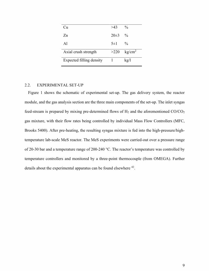
Table 2. MK-121 catalyst properties (catalyst cylinders with domed ends, 6*4 mm)
Property Value
Chemical composition
9
Cu >43 %
Zn 20±3 %
Al 5±1 %
Axial crush strength >220 kg/cm2
Expected filling density 1 kg/l
2.2. EXPERIMENTAL SET-UP
Figure 1 shows the schematic of experimental set-up. The gas delivery system, the reactor
module, and the gas analysis section are the three main components of the set-up. The inlet syngas
feed-stream is prepared by mixing pre-determined flows of H2 and the aforementioned CO/CO2
gas mixture, with their flow rates being controlled by individual Mass Flow Controllers (MFC,
Brooks 5400). After pre-heating, the resulting syngas mixture is fed into the high-pressure/high-
temperature lab-scale MeS reactor. The MeS experiments were carried-out over a pressure range
of 20-30 bar and a temperature range of 200-240 °C. The reactor’s temperature was controlled by
temperature controllers and monitored by a three-point thermocouple (from OMEGA). Further
details about the experimental apparatus can be found elsewhere 42.

10
Figure 1. Schematic of the experimental set-up
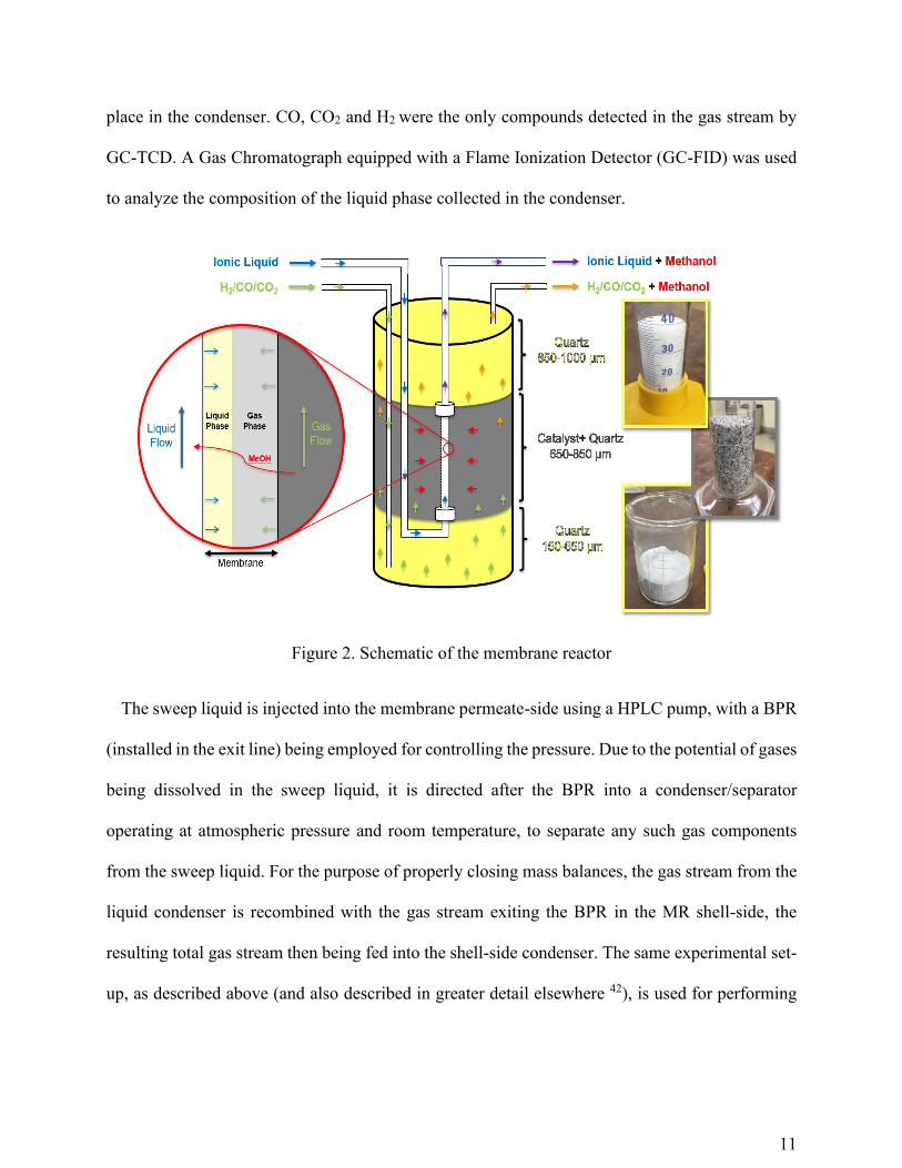
Figure 2 shows a schematic of the MR itself, showing that the reactor is divided into two zones
by a tubular ceramic membrane: the shell-side (reject-side) and the tube-side (permeate-side). The
shell-side contains a packed-bed of catalysts and the MeS reaction occurs in this zone. The
methanol produced is then transported through the membrane and is dissolved into a sweep liquid
that flows in the tube-side. A back-pressure regulator (BPR) is used to control the pressure of the
MR shell-side. A condenser is installed at the outlet of the shell-side to ensure that complete
condensation takes place of the methanol, H2O, and other potential by-products in the gas phase
exiting the reactor. Glass beads are used in the condenser for improving cooling of the gas stream;
a cooling bath containing dry-ice and acetone with the fixed temperature of -78 °C is also used in
which the condenser is immersed. No methanol and other organic compounds were detected (using
a Gas Chromatograph equipped with a Thermal Conductivity Detector (GC-TCD)) in the gas
stream exiting the condenser, which verifies that complete condensation of such compounds takes
11
place in the condenser. CO, CO2 and H2 were the only compounds detected in the gas stream by
GC-TCD. A Gas Chromatograph equipped with a Flame Ionization Detector (GC-FID) was used
to analyze the composition of the liquid phase collected in the condenser.
Figure 2. Schematic of the membrane reactor
The sweep liquid is injected into the membrane permeate-side using a HPLC pump, with a BPR
(installed in the exit line) being employed for controlling the pressure. Due to the potential of gases
being dissolved in the sweep liquid, it is directed after the BPR into a condenser/separator
operating at atmospheric pressure and room temperature, to separate any such gas components
from the sweep liquid. For the purpose of properly closing mass balances, the gas stream from the
liquid condenser is recombined with the gas stream exiting the BPR in the MR shell-side, the
resulting total gas stream then being fed into the shell-side condenser. The same experimental set-
up, as described above (and also described in greater detail elsewhere 42), is used for performing

12
the packed-bed reactor (PBR) experiments; this is accomplished by closing both the inlet and outlet
lines in the tube-side of the membrane.
2.3. EXPERIMENTAL PROCEDURE
As shown in Figure 2, the ceramic membrane is installed in the center of the reactor, which is
an autoclave made of stainless steel. It is attached to the top of the autoclave with flexible stainless
steel tubing that accommodates potential thermal expansion; it is connected to that tubing via
Swagelok fittings and Teflon O-rings. The bottom of the reactor is first loaded with quartz particles
(150 µm to 650 µm in diameter, see Figure 2) up to a level reaching the bottom of the membrane.
The reactor is then packed along the length of the membrane with a mixture of catalyst and quartz
(650 µm to 850 µm in diameter, as described above). A bed of quartz particles (850 µm to 1000
µm in diameter, see Figure 2) is then packed from the top of the membrane all the way to the top
of the autoclave The syngas is fed into the reactor by means of a tube that traverses the length of
the reactor from the top of the autoclave into the middle of the fine quartz particle bed at the bottom
of the reactor. The liquid sweep flows through the flexible tubing connected, on either side to the
membrane (in the PBR mode of operation, the inlet and outlet of the membrane tube-side are
closed). The reactor (in both the PBR and the MR experiments) operates isothermally (temperature
difference across the reactor length: less than 2 oC), and isobarically (pressure drop: less than 0.1
bar).
After calibration of the MFC’s and GC’s, the set-up is tested to ensure that it is leak-free (for
that, the system is pressurized at 30 bar with N2, and the target for leak-free operation is a pressure
drop of <0.2 bar over a 24 h period). Then, the catalyst is activated in situ, following a
hydrogenation treatment protocol recommended by its manufacturer (for further details, see Li

13
and Tsotsis 42). After the catalyst activation step and before starting the experiments, the reactor
is purged with N2 at a flow rate of 600 cc/min for about 1 h; after that, the operating conditions are
adjusted according to the design of experiments. The IL chosen ([EMIM][BF4]) has a relatively
high viscosity at room temperature (~45 cP), therefore, to reduce its viscosity to facilitate pumping,
it is preheated to 50 oC (via a water bath) prior to pumping via the HPLC pump. In order to achieve
a steady-state condition, the outlet composition and flow rate should have negligible variations
(the acceptable range: less than 5% for the concentration and less than 2% for the outlet flow rate);
therefore, beside the pressure and temperature of the reactor, the composition and flow rate of the
outlet gas are monitored accurately via GC-TCD and bubble-flow meters, respectively.
2.4. MEMBRANE MODIFICATION
The membrane’s key role during the reaction is to provide a well-defined interface between the
sweep liquid (permeate-side) and the gas phase in the reactor side (shell-side) for the reaction
products to dissolve into and be carried away by the sweep liquid. Complete wetting of the
membrane by the liquid is not desirable, however, since that creates a large transport resistance.
The ideal configuration, instead, is shown schematically in Figure 3 whereby the liquid is confined
only in the top membrane layer creating an impermeable layer preventing the gas from simply
bubbling through.

14
Figure 3. Gas-liquid interface in a hydrophobic membrane
The M&PT mesoporous ceramic membrane is intrinsically relatively hydrophilic and the sweep
liquids are polar compounds capable to remove the MeOH from the reaction zone; they, thus, have
affinity towards hydrophilic surfaces and are non-wetting toward hydrophobic ones. In order to
prevent the solvent from completely penetrating through, prior to its use in the MR experiments
the membrane surface must be modified to become more hydrophobic. For that, a surface
modification method 46 has been developed, which uses a fluoroalkylsilane (FAS) compound as a
surface modifier that has both hydrolysable groups and hydrophobic ends 47 (the structure of the
FAS compound employed in this study is shown in Figure 4). The mechanism for the surface
modification, reportedly, involves the FAS compound being attached to the metal oxide surface
through a reaction between its hydrolysable groups with the surface hydroxyl groups, as shown in
Figure 4.

15
Figure 4. FAS attachment mechanism during membrane modification 47
Prior to the modification of its surface, the membrane tube is cleaned by ultra-sonification with
ethanol for 30 min and then with de-ionized (DI) water for an additional 30 min (the membrane is
glazed on both ends, ~1 cm, before any modification takes place, to ensure complete sealing when
installed inside the reactor, with the glazing procedure being explained in greater detail in 48).
Then, the membrane is soaked in an ethanol/DI water solution (2:1 volume ratio) for 24 h, and is
then dried in air at 60 °C for 24 h. The dry membrane is then immersed into a FAS/hexane (0.1
mol/l) solution, which is prepared by dissolving FAS into hexane at room temperature under
vigorous stirring for 12 h, ultra-sonicated for 30 min and then left in the FAS solution for an
additional 24 h to allow the surface coupling reaction to complete. The unreacted FAS on the
surface of the membrane is removed by rinsing with hexane solution for several times and then
placed in an oven for 12 h at 100 °C to dry. The aforementioned steps (soaking the membrane in
the FAS/hexane solution, washing and drying) are then repeated four times. As the final step, the
modified membrane gets heated at 200 °C in a furnace for 6 h in flowing Argon.
As it can be seen in Figure 5, which shows DI water droplets on the membrane, the surface
becomes hydrophobic after the modification procedure. In order to quantify the ability of the FAS
modification method to alter the wettability of the membrane surface toward a more hydrophobic

16
one, a number of characterization tests were performed during the initial development of method.
They included break-through pressure tests, contact angle tests, membrane morphology testing via
electron microscopy (SEM), FTIR-DRIFTS characterization, and thermogravimetric analysis
(TGA), the latter to assess whether the surface modification is robust at the temperatures employed
in MeS. Further details regarding the results of the studies can be found elsewhere 49.
We report here contact angle tests with both the modified and unmodified membranes with DI
water, TGDE and IL at room temperature and pressure using a Rame-Hart (Model #290)
automated goniometer, to validate the ability of the method to modify the hydrophilicity
characteristics of the membrane surface. For such testing, the membrane to be studied was cut into
numerous small pieces, each used in a single contact angle measurement. For the unmodified
membranes, liquid droplets placed on their surface (due to the relatively low hydrophobicity of the
surface) vanish quickly, typically after 10 min. Therefore, the contact angle measurements reported
here are taken within the first few seconds after the droplet’s placement on the surface. On the
other hand, the droplets placed on the modified membranes’ surface remain stable for over an hour.
For each droplet, an average of 6 contact angle measurements on different membrane pieces is
reported in the following section.
Figure 5. DI water droplets on the surface of the modified membrane

17
During the MR experiments, the pressure in the tube-side is kept a bit higher (typically, 0.5-1
bar) than that of the shell-side, to assure that the liquid will penetrate into the membrane to block
gas transport. Complete infiltration of the membrane by the solvent is not desirable, however,
because it creates a large resistance for the MeOH molecules to permeate through. To assure than
no solvent penetration and leak-through occurs during the MR experiments, after the membrane is
installed in the reactor and prior to loading the catalyst, the reactor shell-side is pressurized with
N2 at a temperature of 210 °C and a pressure 25 and 7 bar, while the sweep liquid is flowing
through the tube-side (at a flow rate of 0.5 ml/min) at a sufficiently high overpressure to prevent
the gas from bubbling through, but not exceedingly high so that the liquid itself breaks through
(typically <1 bar). After passing through the membrane, the solvent is redirected into a reservoir,
and it is then recycled to the membrane tube-side. The recycling of the sovent enables us to
estimate its loss (leak-through) rate by monitoring the change in the solvent mass in the reservoir.
If less than 1 ml of the IL liquid is lost over a-12 hour period, it is considered that the membrane
surface modification and the membrane sealing are satisfactory, and the membrane overpressure
is sufficiently high.
3. RESULTS AND DISCUSSION
3.1. PBR EXPERIMENTAL RESULTS
In addition to the MR experiments reported here, we have also carried-out PBR experiments to
provide a basis for comparison for the MR experiments, i.e., whether the MR is less or more
efficient than the PBR under the same experimental conditions. These experiments were performed
in the same lab-scale reactor (Figure 2) with the membrane in place but with the permeate-side
inlet and outlet being closed. In the PBR experiments, the effect of five parameters on the

18
performance of the reactor were investigated, including the temperature (T), pressure (P), catalyst
weight to inlet molar flow-rate ratio (W/F), the carbon factor in the feed (CF = mol CO/( mol CO
+ mol CO2)), and the feed stoichiometric number (SN = (mol H2- mol CO2)/(mol CO + mol CO2) ).
The exact experimental conditions investigated and the obtained carbon conversions (defined by
Eq. 1 below) are shown in Table S1 in the Supplementary Materials section.
𝑋𝑐𝑎𝑟𝑏𝑜𝑛 =(𝐹𝑖𝑛𝑙𝑒𝑡 𝐶𝑂+𝐹𝑖𝑛𝑙𝑒𝑡 𝐶𝑂2
)−(𝐹𝑜𝑢𝑡𝑙𝑒𝑡 𝐶𝑂+𝐹𝑜𝑢𝑡𝑙𝑒𝑡 𝐶𝑂2)
(𝐹𝑖𝑛𝑙𝑒𝑡 𝐶𝑂+𝐹𝑖𝑛𝑙𝑒𝑡 𝐶𝑂2)
∗ 100 (1)
where Fi is the molar flow rate (mol/s) of species i at the designated location.
In these studies, after the reactor reaches steady-state (based on the gas phase measurements),
the experiment was run for an additional time period during which time a liquid sample was
collected in the condenser (its volume measured and its composition determined via GC-FID
analysis). This is done in order to close mass balances (by determining the quantity of liquid
products and comparing with the carbon reacted determined via the gas-phase measurements), and
to measure reactor selectivity toward MeOH. For the experiments reported here, both the
selectivity and carbon balance are always higher than 98 %.
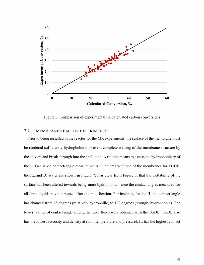
The experimental results were also fitted to global rate expressions for reactions R1 and R3 from
the technical literature 50-52, and to available data for the thermodynamic parameters 53. Figure 6
shows comparison of experimental and calculated carbon conversions (Eq. 1), indicating a
reasonable agreement between the experimental and modeling data.
19
Figure 6. Comparison of experimental vs. calculated carbon conversions
3.2. MEMBRANE REACTOR EXPERIMENTS
Prior to being installed in the reactor for the MR experiments, the surface of the membrane must
be rendered sufficiently hydrophobic to prevent complete wetting of the membrane structure by
the solvent and break-through into the shell-side. A routine means to assess the hydrophobicity of
the surface is via contact-angle measurements. Such data with one of the membranes for TGDE,
the IL, and DI water are shown in Figure 7. It is clear from Figure 7, that the wettability of the
surface has been altered towards being more hydrophobic, since the contact angles measured for
all three liquids have increased after the modification. For instance, for the IL the contact angle
has changed from 78 degrees (relatively hydrophilic) to 122 degrees (strongly hydrophobic). The
lowest values of contact angle among the three fluids were obtained with the TGDE (TGDE also
has the lowest viscosity and density at room temperature and pressure). IL has the highest contact
0
10
20
30
40
50
60
0 10 20 30 40 50 60
Exp
erim
enta
l C
on
ver
sion
, %
Calculated Conversion, %

20
angle among the three liquids, but also the highest viscosity, which further diminishes the chance
of breaking through the membrane and leaking into the shell-side.
Figure 7. Comparison of measured contact angles on modified and unmodified membranes
During the MR experiments, the liquid sweep flowing in the tube-side removes in situ the
methanol generated in the reactor (shell-side), leading to equilibrium shift and enhanced methanol
production. Another important role of the sweep liquid is carrying away the exothermic heat of
reaction. The membrane acts as an interphase contactor in between the reactor side and the product-
removing solvent, without requiring the solvent to come directly in contact with the catalyst, as in
the case of employing a trickle-bed reactor for the same purpose. This, then, helps to reduce the
potential impact of the catalyst on solvent stability, or of the solvent on catalyst activity, thus
extending both their life-times.
In this part of the study, the performance of the membrane reactor was investigated at different
experimental conditions (variables: T, P, sweep liquid flow rates, and W/F) and the results were
0
20
40
60
80
100
120
140
Modified Membrane Unmodified Membrane
Con
tact
An
gle
(d
egre
e)
DI Water
TGDE
IL

21
compared with the PBR under the same conditions (for all such experiments, we kept the
stoichiometric number and the carbon factor constant, i.e., SN = 1.96 and CF=0.625). We have
previously reported [41] experiments with the same catalyst bed and membrane employing TGDE
as the sweep solvent. For this study, prior to carrying-out the experiments with the IL we repeated
several of these experiments with the TGDE as the solvent to verify the state of the membrane and
catalyst. Excellent repeatability in carbon conversion with the previous tests [41] was observed
(error ≤2%).
Figure 8. Effect of W/F on MR and PBR conversion. P = 32 bar, T = 220 °C
Figure 8 shows the carbon conversion for both the MR and PBR as a function of W/F under a
pressure of 32 bar, a temperature of 220 oC, and for two different sweep liquid flow rates (LF),
namely 1 cc/min and 6 cc/min. In this study, the catalyst weight and syngas composition are both
constant, therefore, increasing the W/F means reducing the syngas flow rate. Predictably, the
increase of W/F leads to enhancement in conversions for both the MR and PBR . As it can be seen
35
40
45
50
55
60
65
70
75
80
25 30 35 40 45 50
Con
ver
sion
(%
)
Weight of catalyst/Flow rate (g*h/mol))
MR-IL (LF=6cc/min)
MR-TGDE (LF=6cc/min)
MR-IL (LF=1cc/min)
MR-TGDE (LF=1cc/min)
Equilibrium
PBR

22
from the figure, for larger W/F the PBR conversion approaches the equilibrium value. The
membrane reactor conversions, on the other hand, with both sweep liquids manage to exceed the
equilibrium values. When the IL is used as the sweep liquid, the observed conversions consistently
exceed those measured with the TGDE being employed as the solvent, and are on a relative basis
22.2 - 51.3% higher than the PBR conversions. In addition, the IL offers the advantage of a
significantly lower vapor pressure, which simplifies downstream separation requirements when
compared to TGDE, and also means diminished solvent losses due to vaporization.
Figure 9. Effect of flow rate (liquid sweep) on MR conversion. P = 32 bar, T = 220 oC, W/F =
47.2 g*h/mol
To further investigate the effect of varying the sweep liquid flow rate, a series of experiments
were performed at different sweep liquid flow rates and constant pressure (32 bar), temperature
(220 oC), and W/F (47.2 g*h/mol). The results are presented in Figure 9. For both sweep liquids,
the MR conversion increases with increasing sweep liquid flow rates, attributed to the fact that a
greater amount of methanol is extracted from the shell-side as a result of increasing liquid sweep
30
40
50
60
70
80
90
0 1 2 3 4 5 6 7
Co
nv
ersi
on
(%
)
Flow Rate (cc/min)
Ionic Liquid
TGDE
Equilibrium

23
flow rate, thereby, pushing further the equilibrium conversion to the right toward methanol
generation. The sweep liquid flow rate plays a crucial role in process design optimization: a higher
flow rate results in higher conversions, as Figure 9 amply manifests but, on the other hand, the
resulting solutions have a lower MeOH concentration, and thus are more challenging to separate
the alcohol from.
Figure 10. Effect of temperature on PBR, MR and equilibrium conversion. P = 32 bar, liquid
sweep rate = 1 cc/min, W/F =47.2 g*h/mol.
Figure 10 shows the carbon conversion for the MR and PBR as a function of temperature for a
constant pressure (32 bar), W/F (47.2 g*h/mol), and sweep liquid flow rate (1 cc/min). The rather
narrow range of temperatures studied was due to the fact that the FAS coating gets damaged at
higher temperatures; and because temperatures lower than 200 oC may lead to catalyst
deactivation. In Figure 10, the PBR conversion first increases, passes through a maximum at a
30
35
40
45
50
55
60
190 195 200 205 210 215 220 225
Con
ver
sion
(%
)
Temperature (°C)
MR-IL
MR-TGDE
PBR
Equilibrium
24
certain temperature, and then decreases at the higher temperatures (e.g., reaching a lower
conversion at T= 220 oC compared to that of T=214 oC). This can be explained by the fact that at
the higher temperatures the reactor conversion starts “tracking” the thermodynamic equilibrium
conversion (shown also on the Figure) of this exothermic reaction.
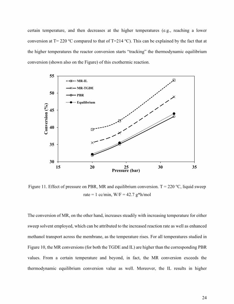
Figure 11. Effect of pressure on PBR, MR and equilibrium conversion. T = 220 oC, liquid sweep
rate = 1 cc/min, W/F = 42.7 g*h/mol
The conversion of MR, on the other hand, increases steadily with increasing temperature for either
sweep solvent employed, which can be attributed to the increased reaction rate as well as enhanced
methanol transport across the membrane, as the temperature rises. For all temperatures studied in
Figure 10, the MR conversions (for both the TGDE and IL) are higher than the corresponding PBR
values. From a certain temperature and beyond, in fact, the MR conversion exceeds the
thermodynamic equilibrium conversion value as well. Moreover, the IL results in higher
30
35
40
45
50
55
15 20 25 30 35
Con
ver
sion
(%
)
Pressure (bar)
MR-IL
MR-TGDE
PBR
Equilibrium
25
conversion due to its higher solubility towards methanol at the reaction conditions, likely, due to
its more polar nature.
Figure 11 shows the effect of changing the reactor pressure on the MR (for both types of sweep
solvent, IL and TGDE) and PBR conversion as well as the thermodynamic equilibrium conversion
while keeping constant the reactor temperature (220 oC), the sweep liquid flow rate (1 cc/min),
and W/F (47.2 g*h/mol). Predictably, both the thermodynamic equilibrium and PBR conversions
(which at this relatively high temperature closely track the equilibrium values) increase with
increasing pressure, due to the fact that the total number of moles reduces as a result of MeS
reaction which is thermodynamically favored at higher pressures. The MR conversion also
increases with increasing pressure, the added reason for that being that a greater pressure means
that a higher amount of methanol will also transport through the membrane to be removed by the
sweep liquid, thereby the equilibrium condition is further shifted towards the methanol generation.
Comparing the MR performance when employing the two different sweep liquids, higher
conversions are obtained for the IL over the whole range of pressures studied, thus manifesting the
advantage in terms of MeS reactor efficiency of using the IL when compared to TGDE. As noted
previously, using the IL portends additional advantages related to diminished solvent loss, lower
potential for damage to the catalyst, and simplified downstream separation requirements.
4. CONCLUSIONS
This paper presents experimental data in support of a novel concept of carrying-out MeS in a
MR. In this reactor, the membrane divides its volume into two sections, the membrane shell-side
and tube-side. A Cu-based commercial MeS catalyst is packed in the shell-side where the reaction
takes place, while a sweep liquid flows in the membrane tube-side; its role is to remove the
produced MeOH from the reaction zone in-situ, thus allowing the reactants to produce more MeOH

26
(“breaking the equilibrium”). A commercial alumina membrane is employed, whose surface is
rendered hydrophobic via modification with a FAS agent, in order to prevent any liquid leakage,
thus avoiding solvent loss and potential catalyst deactivation. In our previous work [41], we used
a petroleum-derived solvent (TGDE) as the sweep liquid to conduct the MR experiments. Though
employing the TGDE allowed the MR to attain higher conversion and yield compared to the PBR,
there are disadvantages relating to its use. They include its relatively low boiling point (275 oC)
that dictates the reaction temperature to be kept rather low. Moreover, though its vapor pressure is
quite low it is still finite, and this creates a concern for potential solvent loss due to vaporization.
Therefore, in this paper we have investigated, instead, a new sweep liquid, specifically the ionic
liquid [EMIM][BF4], that demonstrated during MeS in the MR high solubility towards MeOH,
whose in situ removal from the reactor, similarly to when using the TGDE, resulted in enhanced
MR conversion. The IL solvent’s advantages over TGDE for our MR design include: (1) its
extremely low vapor pressures, which eliminates potential loss of solvent and substantially
simplifies downstream separations; (2) its broad operating temperature range, and high
decomposition temperature, which permit the operation of the MR for a broader region of MeS
conditions. In addition, when using the IL, the observed conversions consistently exceeded those
measured with the TGDE.
One of the key goals of the proposed MeS-MR technology is to attain a sufficiently high per-
pass syngas conversion and yield into MeOH (>85%) to avoid the need for syngas recycle. This is
particularly important, when the aim is to produce alcohols from renewable biomass. Though
limitations with the lab-scale system did not allow in this study to meet the target per-pass yield
(>85%), preliminary process scale-up simulations employing a data-validated model indicate the
potential of the proposed concept to meet such a target. We presently continue to investigate the

27
MeS-MR technology by focusing on optimization and on technical and economic analysis (TEA)
for process scale-up. There are several important optimization conditions one must consider, such
as syngas composition, gas and liquid flow rates, temperature, pressure, catalyst weight and
activity, membrane area, the concentration of MeOH in the solvent, and the fraction of the MeOH
product recovered in the product stream. In our studies, we employ a MR model validated by our
MR experimental data that allows us to investigate process performance under operating
conditions that are not readily accessible by the lab-scale experimental system. Results of these
studies will be presented in an upcoming publication.
ACKNOWLEDGEMENT
The support of the National Science Foundation (Award# CBET-1705180) is gratefully
acknowledged.
AUTHOR INFORMATION
Corresponding Author
* Email address: [email protected]
ABBREVIATIONS
1; MR, membrane reactor 2; MeS, methanol synthesis 3; IL, ionic liquid 4; PBR, packed-bed
reactor 5; FAS, fluoroalkylsilane 6; DI, deionized 7; W/F, catalyst weight/total molar flow rate 8;
TEA, technical and economic analysis.
28
5. REFERENCES
1. Stocker, T., Climate change 2013: the physical science basis: Working Group I
contribution to the Fifth assessment report of the Intergovernmental Panel on Climate Change.
Cambridge University Press: 2014.
2. Unneberg, E.; Kolboe, S., Formation of p-Xylene from Methanol over H-ZSM-5. In
Studies in Surface Science and Catalysis, Elsevier: 1988; Vol. 36, pp 195-199.
3. Conte, M.; Lopez-Sanchez, J. A.; He, Q.; Morgan, D. J.; Ryabenkova, Y.; Bartley, J. K.;
Carley, A. F.; Taylor, S. H.; Kiely, C. J.; Khalid, K., Modified zeolite ZSM-5 for the methanol to
aromatics reaction. Catalysis Science & Technology 2012, 2 (1), 105-112.
4. Zeng, D.; Yang, J.; Wang, J.; Xu, J.; Yang, Y.; Ye, C.; Deng, F., Solid-state NMR studies
of methanol-to-aromatics reaction over silver exchanged HZSM-5 zeolite. Microporous and
mesoporous materials 2007, 98 (1-3), 214-219.
5. Elvers, B., Handbook of fuels. Viley-VCH, Wienhaim 2008.
6. CMAI. World Methanol Analysis. https://www.chemicalonline.com/doc/cmai-completes-
2010-world-methanol-analysis-0001, accessed 2010.
7. CMAI. World Butylenes Analysis. https://ihsmarkit.com/industry/chemical.html, accessed
2010.
8. Behr, A., Methanol: The Basic Chemical and Energy Feedstock of the Future. Asinger’s
Vision Today. Edited by Martin Bertau, Heribert Offermanns, Ludolf Plass, Friedrich Schmidt and
Hans‐Jürgen Wernicke. Angewandte Chemie International Edition 2014, 53 (47), 12674-12674.
9. Aasberg-Petersen, K.; Nielsen, C. S.; Dybkjær, I.; Perregaard, J., Large scale methanol
production from natural gas. Haldor Topsoe 2008, 22.
10. Kirk, R. E.; Othmer, D. F., Encyclopedia of Chemical Technology. Vol. 2. The Interscience
Encyclopedia, Inc; New York: 1953.
11. Zhang, Q.; He, D.; Zhu, Q., Recent progress in direct partial oxidation of methane to
methanol. Journal of Natural Gas Chemistry 2003, 12 (2), 81-89.
12. Choudhary, T.; Goodman, D., Methane decomposition: production of hydrogen and carbon
filaments. Catalysis 2006, 19, 164-183.
13. Abbas, H. F.; Daud, W. W., Hydrogen production by methane decomposition: a review.
International journal of hydrogen energy 2010, 35 (3), 1160-1190.
14. Muradov, N.; Veziroǧlu, T., From hydrocarbon to hydrogen–carbon to hydrogen economy.
International Journal of Hydrogen Energy 2005, 30 (3), 225-237.
15. Merkx, M.; Kopp, D. A.; Sazinsky, M. H.; Blazyk, J. L.; Müller, J.; Lippard, S. J.,
Aktivierung von Disauerstoff und Hydroxylierung von Methan durch lösliche Methan‐
Monooxygenase: eine Geschichte von zwei Eisenatomen und drei Proteinen. Angewandte Chemie
2001, 113 (15), 2860-2888.
16. Espinoza, R.; Du Toit, E.; Santamaria, J.; Menendez, M.; Coronas, J.; Irusta, S., Use of
membranes in Fischer-Tropsch reactors. In Studies in Surface Science and Catalysis, Elsevier:
2000; Vol. 130, pp 389-394.
17. Soltani, M. S., ; Tsotsis, T., Catalytic membrane reactors. . Encyclopedia of Membrane
Science and Technology 2013.
18. Gallucci, F.; Paturzo, L.; Basile, A., An experimental study of CO2 hydrogenation into
methanol involving a zeolite membrane reactor. Chemical Engineering and Processing: Process
Intensification 2004, 43 (8), 1029-1036.
29
19. Barbieri, G.; Marigliano, G.; Golemme, G.; Drioli, E., Simulation of CO2 hydrogenation
with CH3OH removal in a zeolite membrane reactor. Chemical Engineering Journal 2002, 85 (1),
53-59.
20. Rahimpour, M.; Ghader, S., Theoretical investigation of a Pd‐membrane reactor for
methanol synthesis. Chemical Engineering & Technology: Industrial Chemistry‐Plant Equipment‐
Process Engineering‐Biotechnology 2003, 26 (8), 902-907.
21. Struis, R.; Stucki, S., Verification of the membrane reactor concept for the methanol
synthesis. Applied Catalysis A: General 2001, 216 (1-2), 117-129.
22. Rohde, M. P.; Unruh, D.; Schaub, G., Membrane application in Fischer–Tropsch synthesis
reactors—Overview of concepts. Catalysis today 2005, 106 (1-4), 143-148.
23. Chen, G.; Yuan, Q., Methanol synthesis from CO2 using a silicone rubber/ceramic
composite membrane reactor. Separation and purification technology 2004, 34 (1-3), 227-237.
24. Struis, R. P. W. J.; Stucki, S.; Wiedorn, M., A membrane reactor for methanol synthesis.
Journal of membrane science 1996, 113 (1), 93-100.
25. Farsi, M.; Jahanmiri, A., Dynamic modeling of a H2O-permselective membrane reactor to
enhance methanol synthesis from syngas considering catalyst deactivation. Journal of Natural Gas
Chemistry 2012, 21 (4), 407-414.
26. Rohde, M. P.; Unruh, D.; Schaub, G., Membrane application in Fischer− Tropsch synthesis
to enhance CO2 hydrogenation. Industrial & engineering chemistry research 2005, 44 (25), 9653-
9658.
27. Leonard, S.; Miachon, S.; Vanhove, D., In Effet de la nature de la membrane sur la
synthèse de Fischer-Tropsch en réacteur membranaire à lit fixe, MemPro2, 14/05/03-16/05/03,
2003.
28. Vanhove, S., Synthese de Fischer-Tropsch en alimentations separees (IMPBR). Recents
Progres en Genie des Procedes. 2003, 89, 194-198.
29. Rahimpour, M.; Mirvakili, A.; Paymooni, K., A novel water perm-selective membrane
dual-type reactor concept for Fischer–Tropsch synthesis of GTL (gas to liquid) technology. Energy
2011, 36 (2), 1223-1235.
30. Marvast, M. A.; Sohrabi, M.; Zarrinpashne, S.; Baghmisheh, G., Fischer‐Tropsch
Synthesis: Modeling and performance study for Fe‐HZSM5 bifunctional catalyst. Chemical
Engineering & Technology: Industrial Chemistry‐Plant Equipment‐Process Engineering‐
Biotechnology 2005, 28 (1), 78-86.
31. Vakili, R.; Rahimpour, M.; Eslamloueyan, R., Incorporating differential evolution (DE)
optimization strategy to boost hydrogen and DME production rate through a membrane assisted
single-step DME heat exchanger reactor. Journal of Natural Gas Science and Engineering 2012,
9, 28-38.
32. Bayat, M.; Rahimpour, M., Simultaneous hydrogen injection and in-situ H2O removal in
a novel thermally coupled two-membrane reactor concept for Fischer–Tropsch synthesis in GTL
technology. Journal of Natural Gas Science and Engineering 2012, 9, 73-85.
33. Bayat, M.; Rahimpour, M., Simultaneous hydrogen and methanol enhancement through a
recuperative two-zone thermally coupled membrane reactor. Energy Systems 2012, 3 (4), 401-420.
34. Bayat, M.; Rahimpour, M.; Taheri, M.; Pashaei, M.; Sharifzadeh, S., A comparative study
of two different configurations for exothermic–endothermic heat exchanger reactor. Chemical
Engineering and Processing: Process Intensification 2012, 52, 63-73.
30
35. Bayat, M.; Rahimpour, M., Simultaneous utilization of two different membranes for
intensification of ultrapure hydrogen production from recuperative coupling autothermal
multitubular reactor. international journal of hydrogen energy 2011, 36 (12), 7310-7325.
36. Rahimpour, M.; Bayat, M., Production of ultrapure hydrogen via utilizing fluidization
concept from coupling of methanol and benzene synthesis in a hydrogen-permselective membrane
reactor. international journal of hydrogen energy 2011, 36 (11), 6616-6627.
37. Khademi, M.; Rahimpour, M.; Jahanmiri, A., Differential evolution (DE) strategy for
optimization of hydrogen production, cyclohexane dehydrogenation and methanol synthesis in a
hydrogen-permselective membrane thermally coupled reactor. international journal of hydrogen
energy 2010, 35 (5), 1936-1950.
38. Khademi, M.; Setoodeh, P.; Rahimpour, M.; Jahanmiri, A., Optimization of methanol
synthesis and cyclohexane dehydrogenation in a thermally coupled reactor using differential
evolution (DE) method. international journal of hydrogen energy 2009, 34 (16), 6930-6944.
39. Khademi, M.; Rahimpour, M.; Jahanmiri, A., A comparison of a novel recuperative
configuration and conventional methanol synthesis reactor. Chemical Engineering
Communications 2012, 199 (7), 889-911.
40. Bradford, M. C.; Te, M.; Pollack, A., Monolith loop catalytic membrane reactor for
Fischer–Tropsch synthesis. Applied Catalysis A: General 2005, 283 (1-2), 39-46.
41. Khassin, A.; Sipatrov, A.; Yurieva, T.; Chermashentseva, G.; Rudina, N.; Parmon, V.,
Performance of a catalytic membrane reactor for the Fischer–Tropsch synthesis. Catalysis today
2005, 105 (3-4), 362-366.
42. Li, Z.; Tsotsis, T. T., Methanol synthesis in a high-pressure membrane reactor with liquid
sweep. Journal of Membrane Science 2019, 570, 103-111.
43. Domańska, U.; Marciniak, A., Solubility of ionic liquid [emim][PF6] in alcohols. The
Journal of Physical Chemistry B 2004, 108 (7), 2376-2382.
44. Nishida, T.; Tashiro, Y.; Yamamoto, M., Physical and electrochemical properties of 1-
alkyl-3-methylimidazolium tetrafluoroborate for electrolyte. Journal of Fluorine Chemistry 2003,
120 (2), 135-141.
45. Yu, Y. An experimental method to measure the porosity from cuttings: Evaluation and
error analysis. 2013.
46. Lu, J.; Yu, Y.; Zhou, J.; Song, L.; Hu, X.; Larbot, A., FAS grafted superhydrophobic
ceramic membrane. Applied surface science 2009, 255 (22), 9092-9099.
47. Wei, C. C.; Li, K., Preparation and characterization of a robust and hydrophobic ceramic
membrane via an improved surface grafting technique. Industrial & Engineering Chemistry
Research 2009, 48 (7), 3446-3452.
48. Li, Z., Methanol Synthesis in a Contactor-Type Membrane Reactor. PhD Thesis USC.
2017.
49. Soltani, S., Methanol Synthesis in a Membrane Reactor. University of Southern California,
2014.
50. Rozovskii, A. Y.; Lin, G. I., Fundamentals of methanol synthesis and decomposition.
Topics in Catalysis 2003, 22 (3-4), 137-150.
51. Bussche, K. V.; Froment, G., A Steady-State Kinetic Model for Methanol Synthesis and
the Water Gas Shift Reaction on a Commercial Cu/ZnO/Al2O3Catalyst. Journal of Catalysis
1996, 161 (1), 1-10.

31
52. Chinchen, G.; Denny, P.; Parker, D.; Spencer, M.; Whan, D., Mechanism of methanol
synthesis from CO2/CO/H2 mixtures over copper/zinc oxide/alumina catalysts: use of14C-
labelled reactants. Applied Catalysis 1987, 30 (2), 333-338.
53. Graaf, G.; Stamhuis, E.; Beenackers, A., Kinetics of low-pressure methanol synthesis.
Chemical Engineering Science 1988, 43 (12), 3185-3195.
TABLE OF CONTENTS GRAPHIC