Embed Size (px)
DESCRIPTION
The solid bed depth at the discharge end of rotary kilns was experimentally investigated for different massflowrates, rotational speeds, inclination angles and materials using two lab kilns with sizes of 0.4 m (ID)⁎5m(L)and0.25 m (ID)⁎6.7 m (L), respectively. The solid depth at the discharge was found to be several more times higherthan the particle diameter. All parameters according to Saeman's model were combined in a newly developeddimensionless‘Bed depth number’ designated as‘Bd’.Thefilling degree of a solid bed at the discharge can becorrelated withF0=1.75⁎Bd0.5(for an inclination angle between 1° and 4°). The range of the researchedBeddepth number(Bd) is suitable for all industrial kilns. These values should be used as the initial condition, whichwas still unknown before, to solve the differential equation for the profile of the solid bed depth through thecylinder
Citation preview
Powder Technology 197 (2010) 17–24
Contents lists available at ScienceDirect
Powder Technology
j ourna l homepage: www.e lsev ie r.com/ locate /powtec
Experimental investigation of solid bed depth at the discharge end of rotary kilns
Eckehard Specht a,⁎, Yi-Chun Shi a, Herrmann Woche a, Joern Knabbe b, Uwe Sprinz b
a Institute of Fluid Dynamics and Thermodynamics, Otto von Guericke University of Magdeburg, Universitaetsplatz 2, 39106 Magdeburg, Germanyb Claudius Peters Technologies GmbH, Schanzenstraße 40, D-21614 Buxtehude, Germany
⁎ Corresponding author. Tel.: +49 391 6718765; fax:E-mail address: [email protected] (E. Specht
0032-5910/$ – see front matter © 2009 Published by Edoi:10.1016/j.powtec.2009.08.024
a b s t r a c t
a r t i c l e i n f oArticle history:Received 7 March 2009Received in revised form 15 June 2009Accepted 14 August 2009Available online 6 September 2009
Keywords:Rotary kilnSolid depthSolid end depthInitial conditionOut-flowingParticle movement
The solid bed depth at the discharge end of rotary kilns was experimentally investigated for different mass flowrates, rotational speeds, inclination angles andmaterials using two lab kilns with sizes of 0.4 m (ID)⁎5 m (L) and0.25 m (ID)⁎6.7 m (L), respectively. The solid depth at the discharge was found to be several more times higherthan the particle diameter. All parameters according to Saeman's model were combined in a newly developeddimensionless ‘Bed depth number’ designated as ‘Bd’. The filling degree of a solid bed at the discharge can becorrelated with F0=1.75⁎Bd0.5 (for an inclination angle between 1° and 4°). The range of the researched Beddepth number (Bd) is suitable for all industrial kilns. These values should be used as the initial condition, whichwas still unknown before, to solve the differential equation for the profile of the solid bed depth through thecylinder.
+49 391 6712762.).
lsevier B.V.
© 2009 Published by Elsevier B.V.
1. Introduction
Rotary kilns are widely used in chemical industries, cementindustry, metallurgical industry, waste treatment, drying process,incineration process etc. For process modeling and simulation thesolid bed depth in the axial direction of the kiln must be known. Thesolid bed depth influences the heat penetration into the bed and thecontact area to the internal wall. These areas are necessary to calculatethe heat transfer among gas, solid and internal wall in rotary kilns. Thesolid motion in the transverse view has been deeply investigated byMellmann [1]. Different forms of solid motions, such as sliding,slumping, rolling, and the transition behavior between these motionsare well described. The solid transverse motions are found toinfluence the solid axial motion in the kiln. Furthermore, it is alsofound that the change of the bed depth in axial direction inverselyinfluences the solid transverse motion [2], as well as the residencetime of the particles in the active layer [3] and the hold-up of solids inkilns [4]. For the axial bed depth some models exist. These modelsrequire the bed depth at the discharge end as initial condition to solvethe differential equations. However, this actual depth is still unknownfor different operational conditions.
Sullivan et al. [5] firstly carried out experimental work on solid axialtransport and hold-up in kilns in the manufacture of Portland cementclinker. Amodel for the steady state transport of a granular solid through
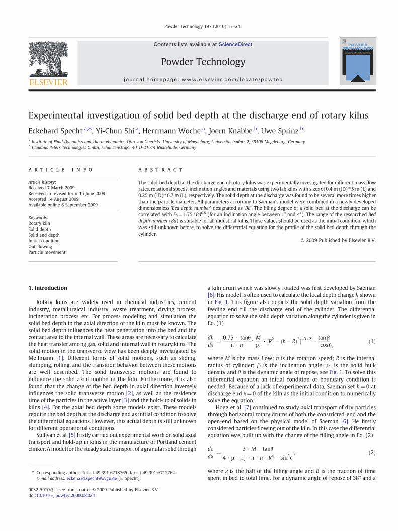
a kiln drum which was slowly rotated was first developed by Saeman[6]. His model is often used to calculate the local depth change h shownin Fig. 1. This figure also depicts the solid depth variation from thefeeding end till the discharge end of the cylinder. The differentialequation to solve the solid depth variation along the cylinder is given inEq. (1)
dhdx
=0:75 · tanθ
π · n⋅ Mρs
· ½R2 � ðh� RÞ2��3=2 � tanβcos θ;
ð1Þ
where M is the mass flow; n is the rotation speed; R is the internalradius of cylinder; β is the inclination angle; ρs is the solid bulkdensity and θ is the dynamic angle of repose, see Fig. 1. To solve thisdifferential equation an initial condition or boundary condition isneeded. Because of a lack of experimental data, Saeman set h=0 atdischarge end x=0 of the kiln as the initial condition to numericallysolve the equation.
Hogg et al. [7] continued to study axial transport of dry particlesthrough horizontal rotary drums of both the constricted-end and theopen-end based on the physical model of Saeman [6]. He firstlyconsidered particles flowing out of the kiln. In this case the differentialequation was built up with the change of the filling angle in Eq. (2)
dεdx
=3 · M · tanθ
4 · μ · ρs · π · n · R4 · sin4ε; ð2Þ
where ε is the half of the filling angle and B is the fraction of timespent in bed to total time. For a dynamic angle of repose of 38° and a
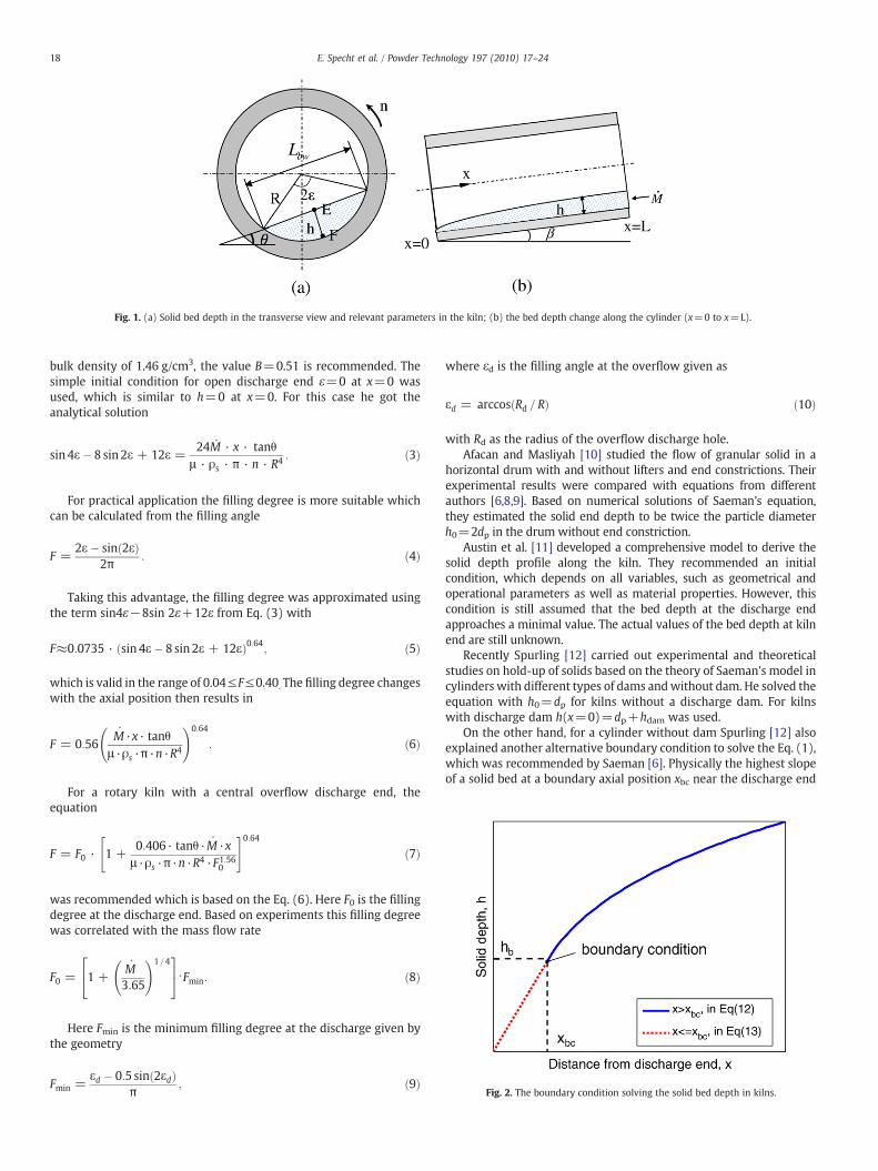
Fig. 1. (a) Solid bed depth in the transverse view and relevant parameters in the kiln; (b) the bed depth change along the cylinder (x=0 to x=L).
Fig. 2. The boundary condition solving the solid bed depth in kilns.
18 E. Specht et al. / Powder Technology 197 (2010) 17–24
bulk density of 1.46 g/cm3, the value B=0.51 is recommended. Thesimple initial condition for open discharge end ε=0 at x=0 wasused, which is similar to h=0 at x=0. For this case he got theanalytical solution
sin 4ε� 8 sin 2ε + 12ε =24M · x · tanθ
μ · ρs · π · n · R4 : ð3Þ
For practical application the filling degree is more suitable whichcan be calculated from the filling angle
F =2ε� sinð2εÞ
2π: ð4Þ
Taking this advantage, the filling degree was approximated usingthe term sin4ε−8sin 2ε+12ε from Eq. (3) with
F≈0:0735 · ðsin 4ε� 8 sin 2ε + 12εÞ0:64; ð5Þ
which is valid in the range of 0.04≤F≤0.40. The filling degree changeswith the axial position then results in
F = 0:56M·x· tanθ
μ ·ρs ·π·n·R4
!0:64
: ð6Þ
For a rotary kiln with a central overflow discharge end, theequation
F = F0 · 1 +0:406· tanθ·M·xμ ·ρs ·π·n·R
4 ·F1:560
" #0:64ð7Þ
was recommended which is based on the Eq. (6). Here F0 is the fillingdegree at the discharge end. Based on experiments this filling degreewas correlated with the mass flow rate
F0 = 1 +M3:65
!1=424
35⋅Fmin: ð8Þ
Here Fmin is the minimum filling degree at the discharge given bythe geometry
Fmin =εd � 0:5 sinð2εdÞ
π; ð9Þ
where εd is the filling angle at the overflow given as
εd = arccosðRd = RÞ ð10Þ
with Rd as the radius of the overflow discharge hole.Afacan and Masliyah [10] studied the flow of granular solid in a
horizontal drum with and without lifters and end constrictions. Theirexperimental results were compared with equations from differentauthors [6,8,9]. Based on numerical solutions of Saeman's equation,they estimated the solid end depth to be twice the particle diameterh0=2dp in the drum without end constriction.
Austin et al. [11] developed a comprehensive model to derive thesolid depth profile along the kiln. They recommended an initialcondition, which depends on all variables, such as geometrical andoperational parameters as well as material properties. However, thiscondition is still assumed that the bed depth at the discharge endapproaches a minimal value. The actual values of the bed depth at kilnend are still unknown.
Recently Spurling [12] carried out experimental and theoreticalstudies on hold-up of solids based on the theory of Saeman's model incylinders with different types of dams andwithout dam. He solved theequation with h0=dp for kilns without a discharge dam. For kilnswith discharge dam h(x=0)=dp+hdam was used.
On the other hand, for a cylinder without dam Spurling [12] alsoexplained another alternative boundary condition to solve the Eq. (1),which was recommended by Saeman [6]. Physically the highest slopeof a solid bed at a boundary axial position xbc near the discharge end
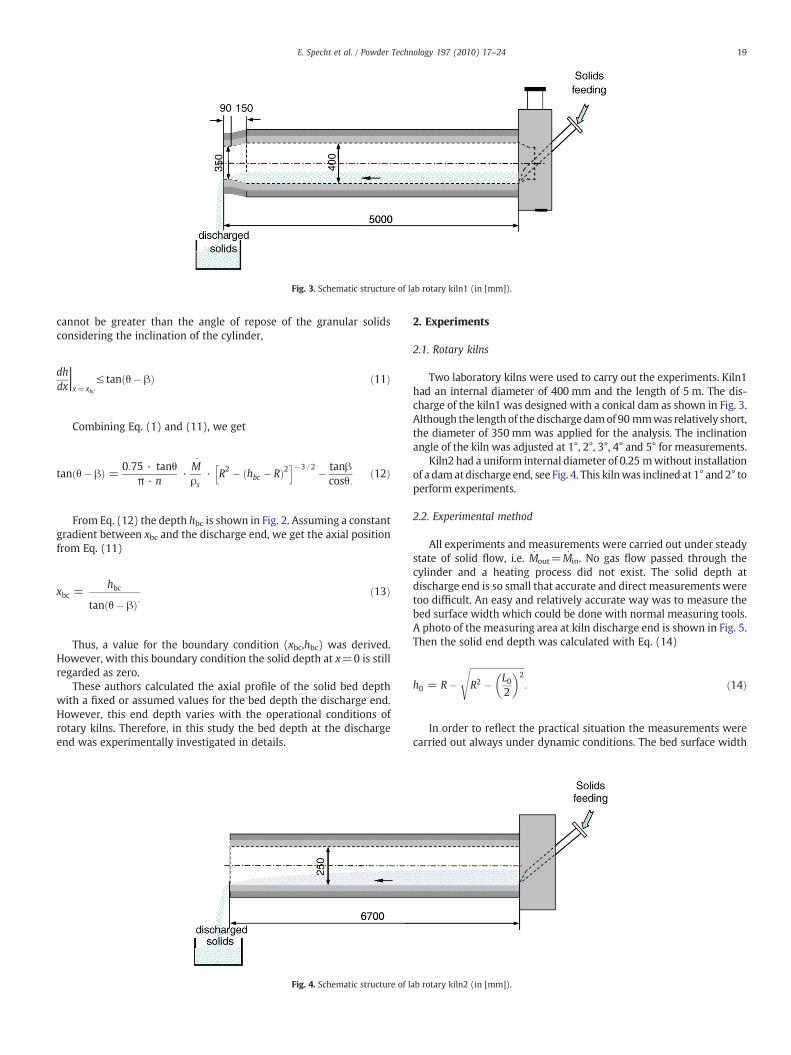
Fig. 3. Schematic structure of lab rotary kiln1 (in [mm]).
19E. Specht et al. / Powder Technology 197 (2010) 17–24
cannot be greater than the angle of repose of the granular solidsconsidering the inclination of the cylinder,
dhdxjx=xbc
≤ tanðθ� βÞ ð11Þ
Combining Eq. (1) and (11), we get
tanðθ� βÞ = 0:75 · tanθπ · n
·Mρs
· R2 � ðhbc � RÞ2h i−3=2 � tanβ
cosθ:ð12Þ
From Eq. (12) the depth hbc is shown in Fig. 2. Assuming a constantgradient between xbc and the discharge end, we get the axial positionfrom Eq. (11)
xbc =hbc
tanðθ� βÞ:ð13Þ
Thus, a value for the boundary condition (xbc,hbc) was derived.However, with this boundary condition the solid depth at x=0 is stillregarded as zero.
These authors calculated the axial profile of the solid bed depthwith a fixed or assumed values for the bed depth the discharge end.However, this end depth varies with the operational conditions ofrotary kilns. Therefore, in this study the bed depth at the dischargeend was experimentally investigated in details.
Fig. 4. Schematic structure of l
2. Experiments
2.1. Rotary kilns
Two laboratory kilns were used to carry out the experiments. Kiln1had an internal diameter of 400 mm and the length of 5 m. The dis-charge of the kiln1 was designed with a conical dam as shown in Fig. 3.Although the length of the dischargedamof 90 mmwas relatively short,the diameter of 350 mm was applied for the analysis. The inclinationangle of the kiln was adjusted at 1°, 2°, 3°, 4° and 5° for measurements.
Kiln2 had a uniform internal diameter of 0.25 mwithout installationof a damat discharge end, see Fig. 4. This kilnwas inclined at 1° and 2° toperform experiments.
2.2. Experimental method
All experiments and measurements were carried out under steadystate of solid flow, i.e. Mout=Min. No gas flow passed through thecylinder and a heating process did not exist. The solid depth atdischarge end is so small that accurate and direct measurements weretoo difficult. An easy and relatively accurate way was to measure thebed surface width which could be done with normal measuring tools.A photo of the measuring area at kiln discharge end is shown in Fig. 5.Then the solid end depth was calculated with Eq. (14)
h0 = R�ffiffiffiffiffiffiffiffiffiffiffiffiffiffiffiffiffiffiffiffiffiffiffiffiffiR2 � L0
2
� �2s
: ð14Þ
In order to reflect the practical situation the measurements werecarried out always under dynamic conditions. The bed surface width
ab rotary kiln2 (in [mm]).
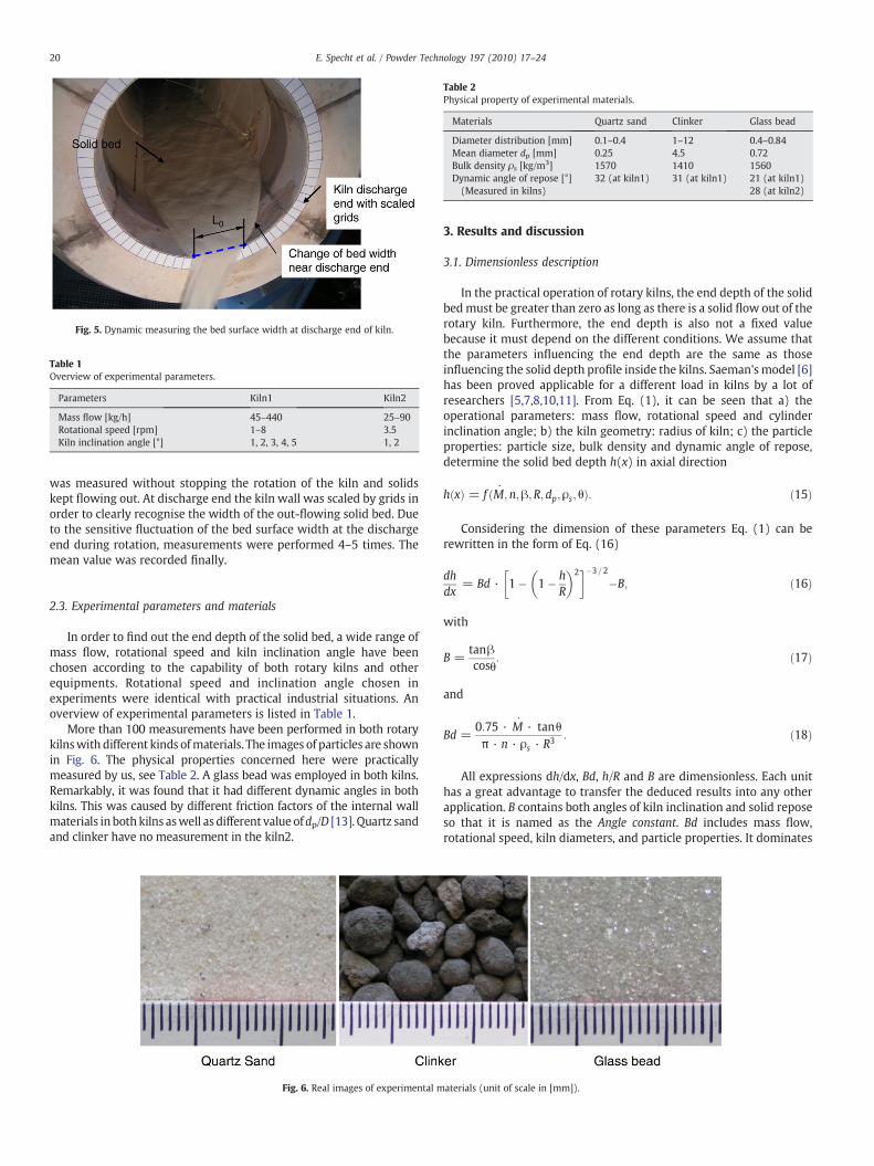
Fig. 5. Dynamic measuring the bed surface width at discharge end of kiln.
Table 1Overview of experimental parameters.
Parameters Kiln1 Kiln2
Mass flow [kg/h] 45–440 25–90Rotational speed [rpm] 1–8 3.5Kiln inclination angle [°] 1, 2, 3, 4, 5 1, 2
Table 2Physical property of experimental materials.
Materials Quartz sand Clinker Glass bead
Diameter distribution [mm] 0.1–0.4 1–12 0.4–0.84Mean diameter dp [mm] 0.25 4.5 0.72Bulk density ρs [kg/m3] 1570 1410 1560Dynamic angle of repose [°](Measured in kilns)
32 (at kiln1) 31 (at kiln1) 21 (at kiln1)28 (at kiln2)
20 E. Specht et al. / Powder Technology 197 (2010) 17–24
was measured without stopping the rotation of the kiln and solidskept flowing out. At discharge end the kiln wall was scaled by grids inorder to clearly recognise the width of the out-flowing solid bed. Dueto the sensitive fluctuation of the bed surface width at the dischargeend during rotation, measurements were performed 4–5 times. Themean value was recorded finally.
2.3. Experimental parameters and materials
In order to find out the end depth of the solid bed, a wide range ofmass flow, rotational speed and kiln inclination angle have beenchosen according to the capability of both rotary kilns and otherequipments. Rotational speed and inclination angle chosen inexperiments were identical with practical industrial situations. Anoverview of experimental parameters is listed in Table 1.
More than 100 measurements have been performed in both rotarykilnswith different kinds ofmaterials. The images of particles are shownin Fig. 6. The physical properties concerned here were practicallymeasured by us, see Table 2. A glass bead was employed in both kilns.Remarkably, it was found that it had different dynamic angles in bothkilns. This was caused by different friction factors of the internal wallmaterials in both kilns aswell as different valueofdp/D [13]. Quartz sandand clinker have no measurement in the kiln2.
Fig. 6. Real images of experimental m
3. Results and discussion
3.1. Dimensionless description
In the practical operation of rotary kilns, the end depth of the solidbedmust be greater than zero as long as there is a solid flow out of therotary kiln. Furthermore, the end depth is also not a fixed valuebecause it must depend on the different conditions. We assume thatthe parameters influencing the end depth are the same as thoseinfluencing the solid depth profile inside the kilns. Saeman'smodel [6]has been proved applicable for a different load in kilns by a lot ofresearchers [5,7,8,10,11]. From Eq. (1), it can be seen that a) theoperational parameters: mass flow, rotational speed and cylinderinclination angle; b) the kiln geometry: radius of kiln; c) the particleproperties: particle size, bulk density and dynamic angle of repose,determine the solid bed depth h(x) in axial direction
hðxÞ = f ðM;n;β;R;dp;ρs; θÞ: ð15Þ
Considering the dimension of these parameters Eq. (1) can berewritten in the form of Eq. (16)
dhdx
= Bd · 1� 1� hR
� �2� ��3=2
�B; ð16Þ
with
B =tanβcosθ
: ð17Þ
and
Bd =0:75 · M · tanθπ · n · ρs · R3 : ð18Þ
All expressions dh/dx, Bd, h/R and B are dimensionless. Each unithas a great advantage to transfer the deduced results into any otherapplication. B contains both angles of kiln inclination and solid reposeso that it is named as the Angle constant. Bd includes mass flow,rotational speed, kiln diameters, and particle properties. It dominates
aterials (unit of scale in [mm]).
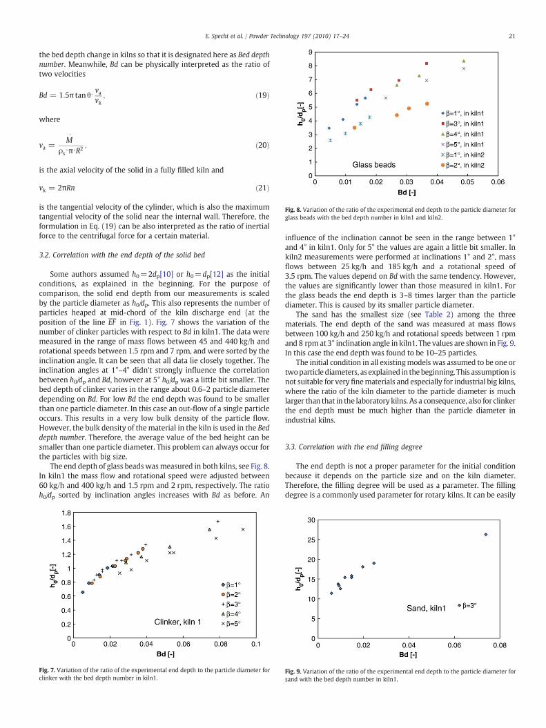
Fig. 8. Variation of the ratio of the experimental end depth to the particle diameter forglass beads with the bed depth number in kiln1 and kiln2.
21E. Specht et al. / Powder Technology 197 (2010) 17–24
the bed depth change in kilns so that it is designated here as Bed depthnumber. Meanwhile, Bd can be physically interpreted as the ratio oftwo velocities
Bd = 1:5π tan θ⋅ vavk
; ð19Þ
where
va =M
ρs⋅π⋅R2 ; ð20Þ
is the axial velocity of the solid in a fully filled kiln and
vk = 2πRn ð21Þ
is the tangential velocity of the cylinder, which is also the maximumtangential velocity of the solid near the internal wall. Therefore, theformulation in Eq. (19) can be also interpreted as the ratio of inertialforce to the centrifugal force for a certain material.
3.2. Correlation with the end depth of the solid bed
Some authors assumed h0=2dp[10] or h0=dp[12] as the initialconditions, as explained in the beginning. For the purpose ofcomparison, the solid end depth from our measurements is scaledby the particle diameter as h0/dp. This also represents the number ofparticles heaped at mid-chord of the kiln discharge end (at theposition of the line EF in Fig. 1). Fig. 7 shows the variation of thenumber of clinker particles with respect to Bd in kiln1. The data weremeasured in the range of mass flows between 45 and 440 kg/h androtational speeds between 1.5 rpm and 7 rpm, and were sorted by theinclination angle. It can be seen that all data lie closely together. Theinclination angles at 1°–4° didn't strongly influence the correlationbetween h0/dp and Bd, however at 5° h0/dp was a little bit smaller. Thebed depth of clinker varies in the range about 0.6–2 particle diameterdepending on Bd. For low Bd the end depth was found to be smallerthan one particle diameter. In this case an out-flow of a single particleoccurs. This results in a very low bulk density of the particle flow.However, the bulk density of the material in the kiln is used in the Beddepth number. Therefore, the average value of the bed height can besmaller than one particle diameter. This problem can always occur forthe particles with big size.
The end depth of glass beads wasmeasured in both kilns, see Fig. 8.In kiln1 the mass flow and rotational speed were adjusted between60 kg/h and 400 kg/h and 1.5 rpm and 2 rpm, respectively. The ratioh0/dp sorted by inclination angles increases with Bd as before. An
Fig. 7. Variation of the ratio of the experimental end depth to the particle diameter forclinker with the bed depth number in kiln1.
influence of the inclination cannot be seen in the range between 1°and 4° in kiln1. Only for 5° the values are again a little bit smaller. Inkiln2 measurements were performed at inclinations 1° and 2°, massflows between 25 kg/h and 185 kg/h and a rotational speed of3.5 rpm. The values depend on Bd with the same tendency. However,the values are significantly lower than those measured in kiln1. Forthe glass beads the end depth is 3–8 times larger than the particlediameter. This is caused by its smaller particle diameter.
The sand has the smallest size (see Table 2) among the threematerials. The end depth of the sand was measured at mass flowsbetween 100 kg/h and 250 kg/h and rotational speeds between 1 rpmand 8 rpmat 3° inclination angle in kiln1. The values are shown in Fig. 9.In this case the end depth was found to be 10–25 particles.
The initial condition in all existingmodels was assumed to be one ortwoparticle diameters, as explained in thebeginning. This assumption isnot suitable for very finematerials and especially for industrial big kilns,where the ratio of the kiln diameter to the particle diameter is muchlarger than that in the laboratory kilns. As a consequence, also for clinkerthe end depth must be much higher than the particle diameter inindustrial kilns.
3.3. Correlation with the end filling degree
The end depth is not a proper parameter for the initial conditionbecause it depends on the particle size and on the kiln diameter.Therefore, the filling degree will be used as a parameter. The fillingdegree is a commonly used parameter for rotary kilns. It can be easily
Fig. 9. Variation of the ratio of the experimental end depth to the particle diameter forsand with the bed depth number in kiln1.
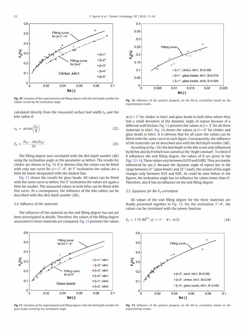
Fig. 10. Variation of the experimental end filling degree with the bed depth number forclinker sorted by the inclination angle. Fig. 12. Influence of the particle property on the Bd–F0 correlation based on the
experimental results.
22 E. Specht et al. / Powder Technology 197 (2010) 17–24
calculated directly from the measured surface bed width L0 and thekiln radius R
ε0 = arcsinL0R
� �; ð22Þ
F0 =2ε0 � sinð2ε0Þ
2π: ð23Þ
The filling degree was correlated with the Bed depth number (Bd)using the inclination angle as the parameter as before. The results forclinker are shown in Fig. 10. It is obvious that the values can be fittedwith only one curve for β=1°–4°. At 5° inclination the values are alittle bit lower designated with the dashed line.
Fig. 11 shows the results for glass beads. All values can be fittedwith the same curve as before. For 5° inclination the values are again alittle bit smaller. The measured values in both kilns can be fitted withthis curve. As a consequence, the influence of the kiln radius can bedescribed with this Bed depth number (Bd).
3.4. Influence of the materials
The influence of the material on the end filling degree has not yetbeen investigated in details. Therefore, the values of the filling degreeassociated to threematerials are compared. Fig. 12 presents the values
Fig. 11. Variation of the experimental end filling degree with the bed depth number forglass beads sorted by the inclination angle.
at β=1° for clinker in kiln1 and glass beads in both kilns where theyhad a small deviation of the dynamic angle of repose because of adifferent wall friction. Fig. 13 presents the values at β=3° for all threematerials in kiln1. Fig. 14 shows the values at β=4° for clinker andglass beads in kiln1. It is obvious that for all cases the values can befitted with the same curve in each figure. Consequently, the influenceof the materials can be described also with the Bed depth number (Bd).
According to Eq. (16) the bed depth in the kiln is not only influencedby Bd but also by Bwhichwas named as the ‘Angle constant’. To check ifB influences the end filling degree, the values of B are given in theFigs. 12–14, Thesevaluesvarybetween0.019and0.082. They aremainlyinfluenced by tan β. Because the dynamic angle of repose lies in therangebetween21° (glass beads) and32° (sand), the cosines of this anglechanges only between 0.93 and 0.85. As could be seen before in thefigures, the inclination angle has no influence for values lower than 4°.Therefore, also B has no influence on the end filling degree.
3.5. Equations for Bd–F0 correlation
All values of the end filling degree for the three materials arefinally presented together in Fig. 15. For the inclination 1°–4°, thevalues can be correlated with the power function
F0 = 1:75⋅Bd0:5 ðβ = 1-� 4-Þ: in ½%� ð24Þ
Fig. 13. Influence of the particle property on the Bd–F0 correlation based on theexperimental results.
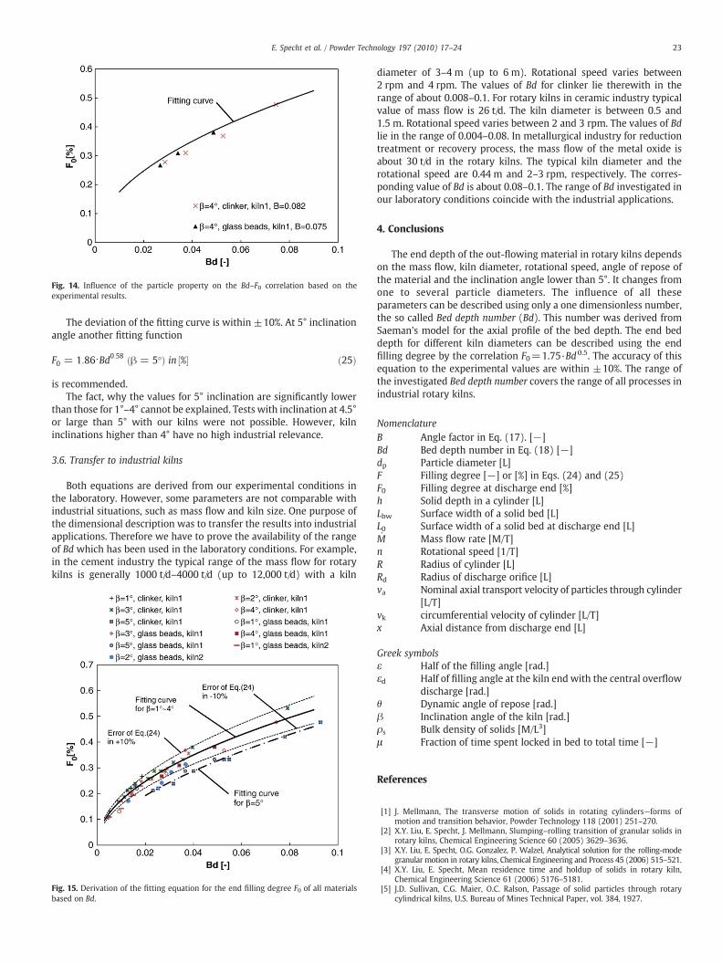
Fig. 14. Influence of the particle property on the Bd–F0 correlation based on theexperimental results.
23E. Specht et al. / Powder Technology 197 (2010) 17–24
The deviation of the fitting curve is within ±10%. At 5° inclinationangle another fitting function
F0 = 1:86⋅Bd0:58 ðβ = 5-Þ in ½%� ð25Þ
is recommended.The fact, why the values for 5° inclination are significantly lower
than those for 1°–4° cannot be explained. Tests with inclination at 4.5°or large than 5° with our kilns were not possible. However, kilninclinations higher than 4° have no high industrial relevance.
3.6. Transfer to industrial kilns
Both equations are derived from our experimental conditions inthe laboratory. However, some parameters are not comparable withindustrial situations, such as mass flow and kiln size. One purpose ofthe dimensional description was to transfer the results into industrialapplications. Therefore we have to prove the availability of the rangeof Bd which has been used in the laboratory conditions. For example,in the cement industry the typical range of the mass flow for rotarykilns is generally 1000 t/d–4000 t/d (up to 12,000 t/d) with a kiln
Fig. 15. Derivation of the fitting equation for the end filling degree F0 of all materialsbased on Bd.
diameter of 3–4 m (up to 6 m). Rotational speed varies between2 rpm and 4 rpm. The values of Bd for clinker lie therewith in therange of about 0.008–0.1. For rotary kilns in ceramic industry typicalvalue of mass flow is 26 t/d. The kiln diameter is between 0.5 and1.5 m. Rotational speed varies between 2 and 3 rpm. The values of Bdlie in the range of 0.004–0.08. In metallurgical industry for reductiontreatment or recovery process, the mass flow of the metal oxide isabout 30 t/d in the rotary kilns. The typical kiln diameter and therotational speed are 0.44 m and 2–3 rpm, respectively. The corres-ponding value of Bd is about 0.08–0.1. The range of Bd investigated inour laboratory conditions coincide with the industrial applications.
4. Conclusions
The end depth of the out-flowing material in rotary kilns dependson the mass flow, kiln diameter, rotational speed, angle of repose ofthe material and the inclination angle lower than 5°. It changes fromone to several particle diameters. The influence of all theseparameters can be described using only a one dimensionless number,the so called Bed depth number (Bd). This number was derived fromSaeman's model for the axial profile of the bed depth. The end beddepth for different kiln diameters can be described using the endfilling degree by the correlation F0=1.75·Bd0.5. The accuracy of thisequation to the experimental values are within ±10%. The range ofthe investigated Bed depth number covers the range of all processes inindustrial rotary kilns.
Nomenclature
B Angle factor in Eq. (17). [−]Bd Bed depth number in Eq. (18) [−]dp Particle diameter [L]F Filling degree [−] or [%] in Eqs. (24) and (25)F0 Filling degree at discharge end [%]h Solid depth in a cylinder [L]Lbw Surface width of a solid bed [L]L0 Surface width of a solid bed at discharge end [L]M Mass flow rate [M/T]n Rotational speed [1/T]R Radius of cylinder [L]Rd Radius of discharge orifice [L]va Nominal axial transport velocity of particles through cylinder[L/T]vk circumferential velocity of cylinder [L/T]x Axial distance from discharge end [L]
Greek symbolsε Half of the filling angle [rad.]εd Half of filling angle at the kiln end with the central overflow
discharge [rad.]θ Dynamic angle of repose [rad.]β Inclination angle of the kiln [rad.]ρs Bulk density of solids [M/L3]μ Fraction of time spent locked in bed to total time [−]
References
[1] J. Mellmann, The transverse motion of solids in rotating cylinders—forms ofmotion and transition behavior, Powder Technology 118 (2001) 251–270.
[2] X.Y. Liu, E. Specht, J. Mellmann, Slumping–rolling transition of granular solids inrotary kilns, Chemical Engineering Science 60 (2005) 3629–3636.
[3] X.Y. Liu, E. Specht, O.G. Gonzalez, P. Walzel, Analytical solution for the rolling-modegranular motion in rotary kilns, Chemical Engineering and Process 45 (2006) 515–521.
[4] X.Y. Liu, E. Specht, Mean residence time and holdup of solids in rotary kiln,Chemical Engineering Science 61 (2006) 5176–5181.
[5] J.D. Sullivan, C.G. Maier, O.C. Ralson, Passage of solid particles through rotarycylindrical kilns, U.S. Bureau of Mines Technical Paper, vol. 384, 1927.

24 E. Specht et al. / Powder Technology 197 (2010) 17–24
[6] W.C. Saeman, Passage of solids through rotary kilns: factors affecting time ofpassage, Chemical Engineering Progress 47 (1951) 508–514.
[7] R. Hogg, K. Shoji, L.G. Austin, Axial transport of dry powders in horizontal rotatingcylinders, Powder Technology 9 (1974) 99–106.
[8] M. Hehl, H. Kroeger, H. Helmrich, K. Schuegerl, Longitudinal mixing in horizontalrotary drum reactors, Powder Technology 20 (1) (1978) 29–37.
[9] A.Z.M. Abhouzeid, D.W. Fuerstenau, A study of the hold-up in rotary drums withdischarge end constrictions, Powder Technology 25 (1980) 21–29.
[10] A. Afacan, J.H. Masliyah, Solids hold-up in rotary drums, Powder Technology 61 (1990)179–184.
[11] L.G. Austin, K. Shoji, R. Hogg, J. Carlson, R.L.C. Flemmer, Flow rates of dry powdersin inclinded rotating cylinders under open-ended discharge conditions, PowderTechnology 20 (1978) 219–225.
[12] Spurling, R.J. Granular flow in an inclined rotating cylinder: steady state and transients.Ph.D. Thesis, Department of Chemical Engineering, University of Cambridge (2000).
[13] X.Y. Liu, E. Specht, J. Mellmann, Experimental study of the lower and upper anglesof repose of granular materials in rotating drums, Powder Technology 154 (2005)125–131.