Embed Size (px)
Citation preview
1
EXPERIMENTAL INVESTIGATION OF REINFORCED CONCRETE 1
T-BEAMS STRENGTHENED IN SHEAR WITH EXTERNALLY 2
BONDED CFRP SHEETS 3
Robert M. Foster1, Monika Brindley
2, Janet M. Lees
3, Tim J. Ibell
4, Chris T. Morley
5, Antony 4
P. Darby6, Mark C. Evernden
7 5
6
An experimental investigation was undertaken into the effectiveness of unanchored and 7
anchored externally bonded (EB) U-wrapped carbon fibre reinforced polymer (CFRP) shear 8
strengthening for reinforced concrete T-beams at a range of realistic sizes. The T-beam sizes, 9
geometry and reinforcement were chosen to reflect existing slab-on-beam structures with low 10
levels of transverse steel shear reinforcement. Geometrically similar reinforced concrete T-11
beams were tested across three sizes ranging from 360 to 720 mm in depth and with different 12
amounts of EB CFRP shear reinforcement. The beams were subjected to three-point bending 13
with a span to depth ratio of 3.5. All the beams failed in diagonal shear. The experimental 14
results indicate significant variability in the capacity of unstrengthened control beams, and a 15
number of these control beams showed greater shear capacity than their EB CFRP 16
strengthened counterparts. Greater thicknesses of CFRP reinforcement did not lead to 17
increased shear capacity compared with lesser thicknesses of unanchored or anchored EB 18
CFRP, but anchored EB CFRP did lead to moderate increases in shear capacity compared to 19
both control and unanchored EB CFRP strengthened beams. 20
21
1 Research Associate, Department of Architecture, University of Cambridge, UK. Corresponding author, email:
[email protected] 2 PhD Candidate, Department of Architecture & Civil Engineering, University of Bath, UK
3 Reader in Civil Engineering, Department of Engineering, University of Cambridge, UK
4 Professor, Department of Architecture & Civil Engineering, University of Bath, UK
5 Former Senior Lecturer, Department of Engineering, University of Cambridge, UK
6 Reader, Department of Architecture & Civil Engineering, University of Bath, UK
7 Senior Lecturer, Department of Architecture & Civil Engineering, University of Bath, UK
2
Keywords: reinforced concrete T-beam, shear strengthening, externally bonded carbon fibre 22
reinforced polymer fabric, size effect 23
24
INTRODUCTION 25
Accurate assessment of the actual strength of reinforced concrete structures and the need for 26
effective strengthening are a growing concern worldwide. This applies both to buildings and 27
to infrastructure, with infrastructure being the area of greater economic concern. The cost of 28
assessing and strengthening deficient bridge structures alone has been estimated as being in 29
excess of £4 billion for the UK (Middleton 2004) and $140 billion for the US (American 30
Association of State Highway Transportation Officials 2008). 31
32
Deficiencies in the strength of reinforced concrete infrastructure can arise due to a variety of 33
factors including accidental damage, construction defects, deterioration, changes in 34
understanding, changes in use and failure to design for future loading. The demolition and 35
replacement of such structures can involve large capital expenditure, environmental impacts, 36
interruptions to service, over-burdening of nearby infrastructure, and local opposition to 37
construction. 38
39
Approaches to strengthening existing concrete structures in-situ are therefore of considerable 40
interest to infrastructure owners seeking to extend a structure’s useful life. Of interest as 41
materials for use in concrete strengthening applications are fibre reinforced polymers (FRPs) 42
and in particular carbon fibre reinforced polymers (CFRPs), primarily due to their favourable 43
strength-to-weight ratios and resistance to various forms of corrosion. FRP strengthening for 44
reinforced concrete structures has been the subject of extensive research (Bakis et al. 2002). 45
FRP materials are currently in use in strengthening and repair applications, and design 46
3
guidance exists in a number of jurisdictions for embedded and externally bonded (EB) 47
strengthening for axial, flexural, shear and seismic applications (RILEM 2016). 48
49
A common structural form that may require shear strengthening is that of a slab-on-beam 50
arrangement. While there is extensive evidence that slab-on-beam structures, usually 51
modelled experimentally by T-beams, are often stronger in shear than similar rectangular 52
beams (Pansuk & Sato 2007), only the contribution of the web section is typically considered 53
for the purposes of design. EB CFRP reinforcement may be preferred in many strengthening 54
applications as it avoids the need to remove areas of concrete or drill into the section with the 55
associated risks of exposing or damaging existing reinforcement. However, in the case of a 56
T-beam, the presence of the flange means that such a strengthening system cannot be fully 57
wrapped around the beam. This commonly leads to partial ‘U-wrapping’ of the accessible 58
down-stand portion of the beam in which the CFRP anchorage relies entirely on surface 59
bonding to the web cover concrete. The CFRP anchorage may thus terminate below the 60
neutral axis, which in most T-beams occurs within the depth of the flange. This means that 61
the CFRP anchorage is located in a region of tension, and that the tension and compression 62
regions are not connected by the CFRP reinforcement. 63
64
While a large number of experimental investigations on the FRP shear strengthening of 65
reinforced concrete have been carried out, an analysis by Lima & Barros (2011) of a database 66
of over 250 EB CFRP shear strengthened beams indicated that the mean height of tested 67
beams was approximately 350 mm, with 54% of beams having a concrete compressive 68
strength between 20 and 30 MPa, and 51% having no shear reinforcement. Only half of the 69
tests considered a U-wrapped CFRP arrangement and 83% of tests were carried out on 70
rectangular beams. Although guidance exists for U-wrapped FRP strengthening systems, 71
4
evaluation of a number of these models against the beams in this data set led Lima & Barros 72
(2011) to conclude that none of the available analytical formulations predicted the 73
contribution of EB FRP systems for the shear strengthening with sufficient accuracy. Some 74
recent investigations have provided experimental evidence of a lack of conservatism in the 75
prediction of the FRP contribution to shear resistance (Dirar et al. 2012, Mofidi & Chaallal 76
2014). Investigators have also reported results indicating that increasing the CFRP thickness 77
in EB FRP systems may not result in increased gains in shear strength (Bousselham & 78
Chaallal 2006) and that a strengthened beam can fail at a lower shear load than a nominally-79
identical unstrengthened control beam (Deniaud & Cheng 2001). Test series investigating the 80
shear strengthening of prestressed I-girders have identified that the EB FRP contribution to 81
be strongly influenced by the cross-sectional geometry and that the provision of EB FRP 82
strengthening can lead to a reduction in shear capacity (Murphy et al. 2012). Investigators 83
(Mofidi et al. 2012, Ozden et al. 2014) have reported that greater effectiveness of the external 84
shear-strengthening system could be achieved when the CFRP sheets are anchored in the 85
compression zone of the beam as proposed by Khalifa et al. (1999). This paper presents 86
details of an investigation carried out in order to provide new experimental data with which 87
to evaluate the influence of size, CFRP ratio and anchorage condition in realistically-sized 88
CFRP-strengthened T-beams with internal transverse steel reinforcement. 89
90
RESEARCH SIGNIFICANCE 91
This research investigates the shear behaviour of reinforced concrete T-beams with low 92
levels of transverse steel reinforcement strengthened with U-wrapped CFRP fabrics at a 93
range of realistic sizes. Three sizes of geometrically scaled T-beams of 360, 540 and 720 mm 94
depth, with a shear span to depth ratio of 3.5, were tested in three-point bending until failure 95
in shear. Unstrengthened control beams at each size were tested, as were beams strengthened 96
5
with varying thicknesses of CFRP. The 540 and 720 mm high beams were also tested with 97
anchored CFRP, with the additional anchorage provided by a longitudinal near-surface-98
mounted bar-in-slot system. By testing multiple unstrengthened control specimens, this study 99
provides experimental evidence of the variability of control specimens and the influence of 100
the variability of the underlying reinforced concrete T-beam on the effectiveness of CFRP 101
strengthening. This area has been largely unaddressed by previous investigations into CFRP 102
shear strengthening. This research also provides important experimental evidence that, in at 103
least some cases, the capacity of the unanchored EB CFRP strengthened beams was lower 104
than that of unstrengthened counterparts. 105
106
EXPERIMENTAL PROGRAMME 107
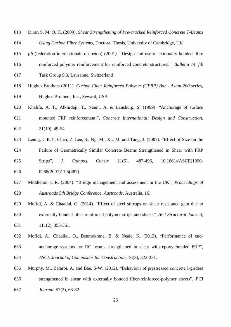
Test series 108
The T-beam test series presented here was carried out as part of a joint experimental 109
programme at the University of Bath and the University of Cambridge investigating the 110
behaviour of reinforced concrete T-beams strengthened with CFRP materials. A total of 15 111
reinforced concrete T-beams were designed to fail in shear under three-point bending. Beams 112
are designated by a letter ‘L’ for large, ‘M’ for medium and ‘S’ for small followed by a ‘B’ 113
indicating testing at Bath or a ‘C’ indicating testing at Cambridge. In the case of 114
unstrengthened control beams, this second letter is followed by a ‘C’, with a subscript 115
differentiating between multiple control beams ‘C1’, ‘C2’. In the case of beams with CFRP 116
strengthening, the second letter is followed by a number indicating the percentage of CFRP 117
provided and followed by a letter ‘U’ indicating an unanchored U-wrapped configuration or 118
‘UA’ indicating an anchored U-wrapped configuration. For example, a small beam with 1 119
layer of 0.5 mm thick U-wrapped CFRP strengthening (0.7%) and tested in Cambridge is 120
designated SC0.7U. 121
6
122
The T-beam geometry was scaled in order to investigate the effect of size on CFRP 123
strengthened beam behaviour. The concrete cover was also scaled, with nominal cover cnom 124
of 40 mm, 30 mm and 20 mm for the large, medium and small beams respectively. Aggregate 125
size was not scaled. The specimen geometries and reinforcement arrangement are shown in 126
Fig. 1. 127
128
The T-beams were designed with a transverse reinforcement ratio of 0.1%, in order to 129
investigate the behaviour of structures with very low transverse reinforcement provision. In 130
the test span, shear reinforcement was provided in the form of closed links fabricated from 131
plain mild steel bar. Mild steel was chosen partly to reflect material properties of reinforcing 132
steel found in many historic structures and partly to provide an adverse case for load share 133
between the steel and the CFRP strengthening. The internal transverse steel reinforcement in 134
the test span was spaced at 0.6d. In order to ensure failure in the test span, substantial 135
transverse reinforcement was provided to the non-test span in the form of deformed steel 136
links at a transverse reinforcement ratio of approximately 0.5%. The main flexural 137
reinforcement consisted of six bars arranged in two layers, as shown in Fig. 1. The 138
longitudinal tension reinforcement ratio based on web area was 2.2% for the large beams, 139
2.4% for the medium beams and 3.5% for the small beams. It should be noted that, due to a 140
fabrication drawing error, the longitudinal reinforcement ratio for the small beams is rather 141
higher than for the medium and large beams. 142
143
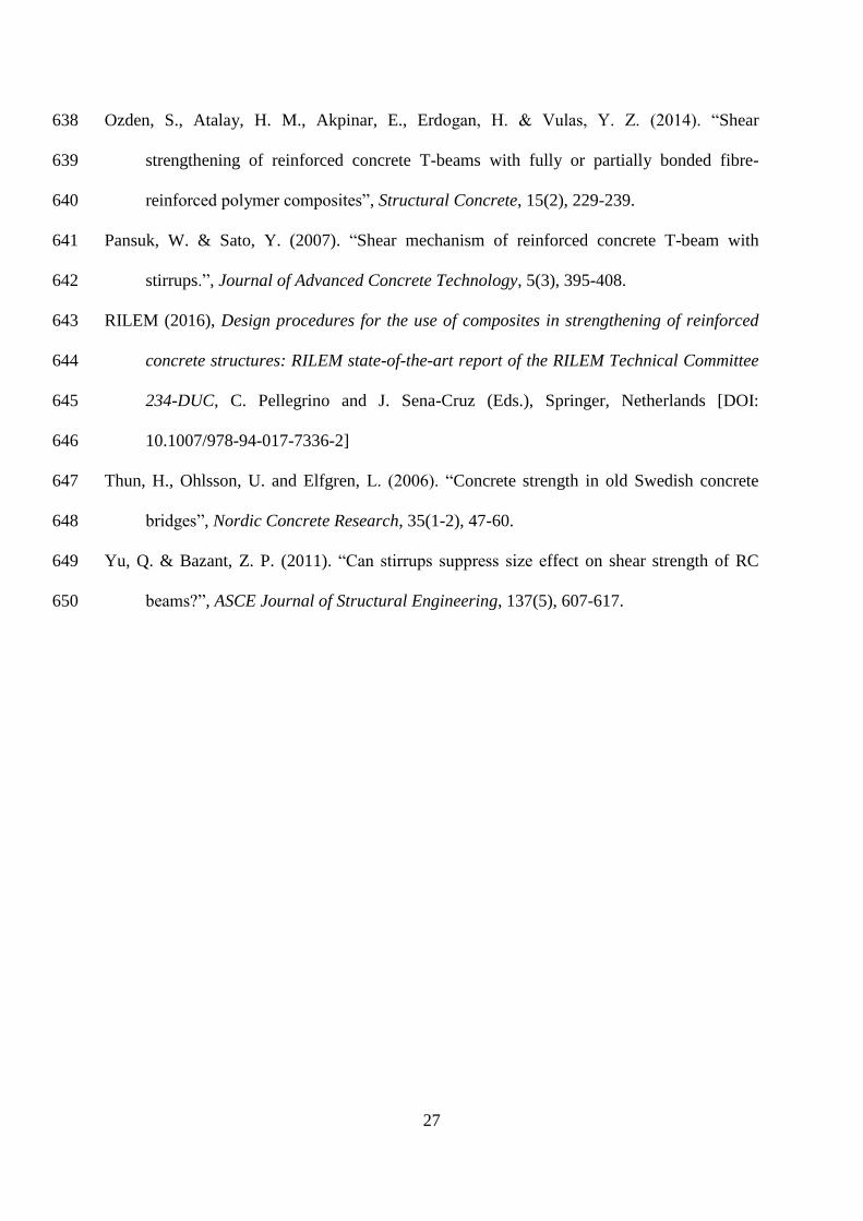
For the strengthened systems, two arrangements were considered: externally bonded 144
continuous CFRP sheets without end anchorage and CFRP sheets anchored with a near 145
surface mounted bar-in-slot anchorage system. The CFRP arrangements are shown in Fig. 2. 146
7
The beams were designed and constructed to reflect some of the constraints typical of 147
existing concrete structures. A chamfered 45° haunch detail was provided, which is typical 148
for cast-in-place slab-on-beam structures and reduces the vertical bonded length available for 149
the CFRP sheets. This detail is provided to both strengthened and unstrengthened control 150
beams. The externally bonded sheets were applied in a U-wrap configuration with CFRP 151
sheets bonded to three sides of the beam. The anchored U-wrap configuration was further 152
provided with a continuous near-surface-mounted bar-in-slot anchorage system at the base of 153
the haunch detail. The CFRP thickness was varied in order to investigate the influence of 154
CFRP reinforcement ratio ρfrp on behaviour. Two weights of carbon fibre fabric were used in 155
order to target ρfrp of 0.7% and 1.3%. Due to the limited fabric weights available, the medium 156
sized beam with one layer of fabric MC0.9U was provided with ρfrp of 0.9%. Details of the 157
test matrix are presented in Table 1. 158
159
The large beams and three medium beams were tested at the University of Bath. The small 160
beams and three medium beams were tested at the University of Cambridge. All beams were 161
fabricated at the same precast facility using the same concrete mix design and aggregate 162
source. The same formwork was used for the medium-sized beams tested at both Bath and 163
Cambridge. The longitudinal reinforcement and the transverse reinforcement in the non-test 164
span were supplied by the precaster. Transverse reinforcement in the test span was supplied 165
and instrumented by the authors. Fabrication of the reinforcement cages and the casting of the 166
beams were overseen by the authors in order to ensure good quality control procedures. 167
168
Material properties 169
The concrete used in this study was made up of coarse limestone aggregate (20 mm 170
maximum dimension), fine grit-sand aggregate and ordinary Portland cement, with a water-171
8
cement ratio of 0.53. A concrete compressive cube strength of 60 MPa was targeted in line 172
with the higher present-day concrete strengths of many historic concrete structures (Thun et 173
al. 2006). All beams were cured for a minimum of 28 days prior to the application of CFRP 174
strengthening. The mean concrete cube strength for each beam on test day is shown in Table 175
1. 176
177
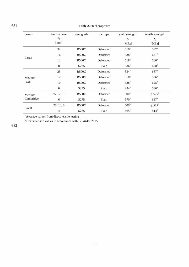
Plain mild steel bar, nominally S275, was used for transverse steel links in the test span. All 178
other steel reinforcement was deformed high yield steel bar. Steel reinforcement properties 179
were determined by direct tensile testing. The results of the direct tensile testing on steel are 180
summarized in Table 2. Where direct tensile test results were not obtained, characteristic 181
values are given following BS 4449 (2005). 182
183
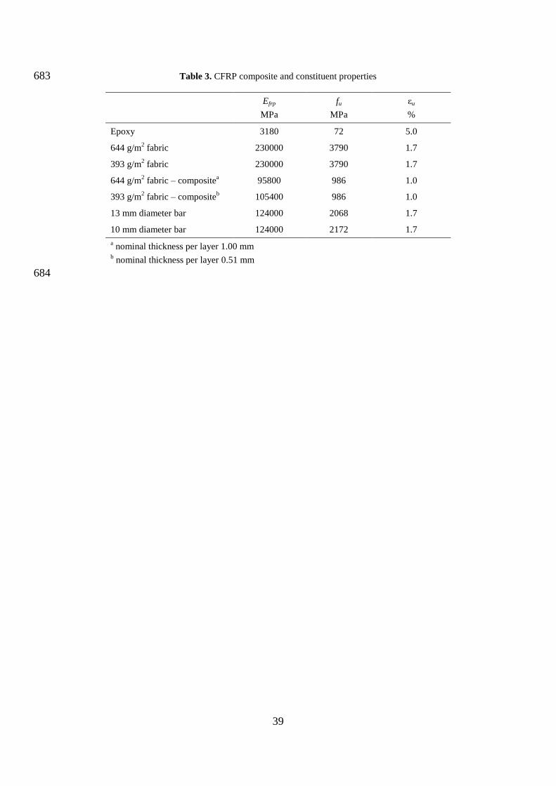
The externally bonded CFRP used in this study was a commercial system comprised of one 184
or more layers of carbon fibre fabric acting compositely with a two-part epoxy resin matrix. 185
Two fabrics were used in this study, with dry fibre content of 644 g/m2 and 393 g/m
2 186
respectively – in conjunction with an epoxy resin. In both fabrics the weave is effectively 187
uni-directional, having only a small number of aramid or carbon fibres perpendicular to the 188
primary carbon fibre direction, in order to maintain the integrity of the loose fabric. The 189
CFRP bars used for anchorage were spiral-wound sand-coated bars. Material properties for 190
the CFRP materials obtained from the manufacturers’ data sheets (Tyfo 2013a, 2013b, Aslan 191
2011) are summarised in Table 3. The bond strengths of the concrete and the CFRP-concrete 192
interface for the Bath beams were determined post-test in the undamaged regions of the 193
reaction span according to ASTM D7522. The mean values of bond strength to the concrete 194
surface fb were 2.6 MPa for both the large and the medium beams. The mean bond strengths 195
of the CFRP to the concrete fbf were 3.0 MPa and 3.5 MPa for the large and the medium 196
9
beams respectively, greatly exceeding the 1.4 MPa minimum tension adhesion strength 197
requirements of ACI440.2R-08 (ACI 2008). 198
199
Beam fabrication and strengthening 200
Beams were cast in high quality stiffened timber formwork which was struck after 201
approximately 24 hours and the moulds cleaned, oiled and reused for the next beam. While 202
pouring, the concrete mix was vibrated with pokers to ensure good compaction. The beams 203
were cast web down – as an in-situ beam would be cast on site – with the main longitudinal 204
tension reinforcement in the ‘good bond’ zone (BSI 2004). After a minimum 28 days, the 205
web portion of the test span of beams to receive externally bonded CFRP was prepared to 206
remove any loose surface material in accordance with the manufacturer’s guidance (Tyfo 207
2013a and 2013b). Due to local constraints, differing surface preparation methods were used 208
across the beam series. However, visual inspection indicated that there was no significant 209
variation in the finish achieved and all methods suitably removed the external cement paste 210
layer to expose the underlying aggregate. The large beams were prepared by ‘dry sponge 211
blasting’; the medium Bath beams were prepared by wet grit blasting followed by a two week 212
drying period; and the medium and small Cambridge beams were prepared by hand-held disk 213
grinding. Discussion with the CFRP manufacturer’s technical representative indicated that, in 214
their experience, all three preparation methods are suitable and that while surface preparation 215
is an important consideration in the case of deteriorating or damaged concrete in existing or 216
historic structures, it is less critical in the case of undeteriorated concrete. The web soffit 217
corners were ground to a recommended minimum radius of 25 mm to prevent premature 218
failure of CFRP due to stress concentrations at the corners. For the bar-in-slot anchorage 219
system, slots were chased along the haunch detail to provide clearance of 30 mm x 30 mm 220
10
and 25 mm x 25 mm for large and medium beams respectively. The corners of the slot were 221
ground to a radius of only 15 mm due to space limitations. 222
223
The CFRP was applied in a wet lay-up system. An initial priming layer of epoxy resin was 224
brushed onto the prepared concrete surface. The carbon fibre fabric, cut to size, was saturated 225
with epoxy by roller and then applied to the concrete with the principal fibre direction aligned 226
perpendicular to the longitudinal axis of the beam. In order to remove air bubbles and ensure 227
that the material was suitably bedded against the concrete substrate, a roller was applied in 228
the principal fibre direction. A further coat of epoxy was brushed over to ensure full coverage 229
of the fibres and provide protection. Where a second layer of fabric was applied, the epoxy 230
coat provided a primed base for the second layer and the process was repeated. In the case of 231
the Bath beams, the epoxy was thickened with silica fume approved by the manufacturer. For 232
the anchored U-wrap strengthening systems, the CFRP sheets were applied as for unanchored 233
cases and secured by continuous CFRP bars coated with thickened epoxy and inserted by 234
hand into the prepared slots. CFRP bar diameters of 12 mm and 10 mm were used for the 235
large and medium beams respectively. All beams tested at Bath were prepared and 236
strengthened along the entire length of the beam by specialist contractors. Specimens 237
strengthened at Cambridge were prepared and strengthened in-house in the test span in 238
accordance with the manufacturer’s guidance (Tyfo 2013 and 2013b) and following training 239
by a specialist contractor. In both cases the procedures were instructed and supervised by the 240
authors. 241
242
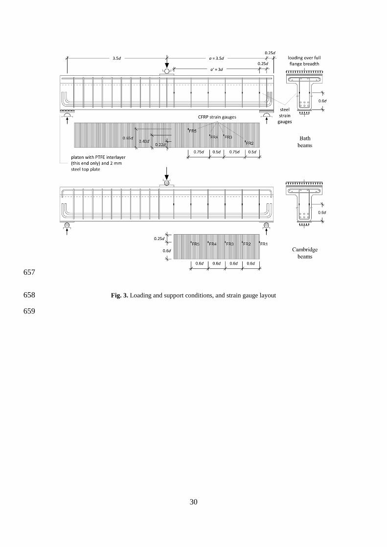
Loading and instrumentation 243
The loading arrangements in the two test facilities were statically equivalent, but the actual 244
test set-up was not identical. At Bath, the load was applied through the central support from 245
11
above using an automatic hydraulic Instron testing machine with maximum capacity 2000 kN 246
at a displacement rate 1 mm/min. To achieve support conditions consistent with a simply 247
supported beam, two layers of oiled PTFE sheets were inserted between the supporting steel 248
plates in the tested span region to create a sliding pin. At Cambridge, the beams were tested 249
under displacement control at a manually controlled displacement rate using a 5000 kN 250
Amsler column testing rig. Load was applied from below to the end supports through a 251
spreader beam and the reaction was provided by the central support above. Simply supported 252
conditions were achieved through the use of a captured pin at the central support and sliding 253
pins at the end supports. In both arrangements the load at the central support was applied 254
across the width of the flange. The loading and support conditions are shown in Fig. 3. 255
256
The transverse steel reinforcement in the test span of all beams was equipped with single-257
direction strain gauges on both legs of the stirrup at mid-height of the link. The strain gauges 258
applied to the EB CFRP sheets of the Bath beams were three-directional strain gauge rosettes. 259
The strain gauges on CFRP were located based on an assumed main shear crack location to 260
capture debonding processes. For the Cambridge beams the strain gauges applied to the EB 261
CFRP were single directional strain gauges aligned with the principal fibre direction of the 262
CFRP and positioned at mid-height at the link positions. In this way the strains in the CFRP 263
and the transverse steel reinforcement were obtained at similar locations. The strain gauge 264
layout for the steel reinforcement and CFRP strengthening is shown in Fig. 3. 265
266
TEST RESULTS AND DISCUSSION 267
All test specimens failed in diagonal shear. The failure of the CFRP strengthened beams was 268
preceded by progressive separation of the CFRP material. Separation of the CFRP was 269
identified post-test as having occurred through the cover concrete in all cases. The ultimate 270
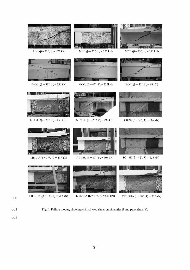
12
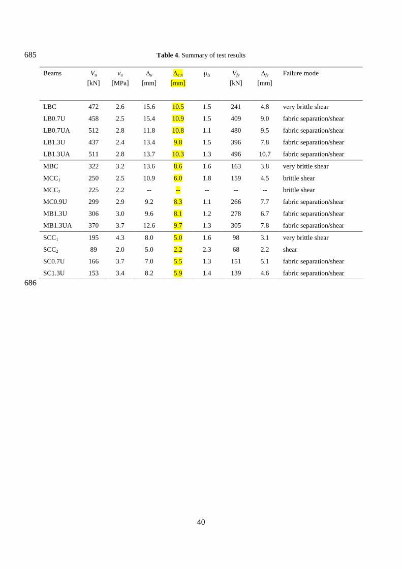
shear force Vu was recorded at failure with corresponding mid-span displacement, Δu. The 271
shear force at steel yield strength Vfy was determined from strain gauge readings on the 272
transverse steel reinforcement at the load where strain gauges registered the first yielding. 273
Due to differences in the yield strength of the steel used, the yield strains obtained by direct 274
tensile testing were 0.0016 and 0.0020 for large and medium Bath beams, and 0.0029 and 275
0.0024 for the medium and small Cambridge beams. Corresponding mid-span displacements 276
Δfy were also determined from the test data. A summary of the test results is presented in 277
Table 4. A malfunction of the data acquisition systems during the testing of beam MCC2 278
means that the relationship between load and measured strains and displacements cannot be 279
reliably determined. However, the applied load was captured by a secondary system allowing 280
the peak shear force to be given with reasonable confidence. 281
282
Significant variation in shear load capacity was observed between unstrengthened control 283
beams. This variation was observed both between beams tested at the same facility, SCC1 and 284
SCC2; and between beams tested at different facilities, MBC and MCC1 / MCC2. In all cases, 285
the beams provided with unanchored EB CFRP failed at lower loads than those of the 286
stronger of their respective control specimens. Beams provided with anchored EB CFRP 287
reached higher loads than both their respective control beams and their unanchored 288
counterparts. However, the increase in strength associated with the anchored EB CFRP was 289
small when considered with reference to the stronger of the relevant control beams. 290
Increasing ρfrp did not, in most cases, lead to increasing shear strength for either anchored or 291
unanchored EB CFRP. Values of Vfy were significantly greater for the CFRP strengthened 292
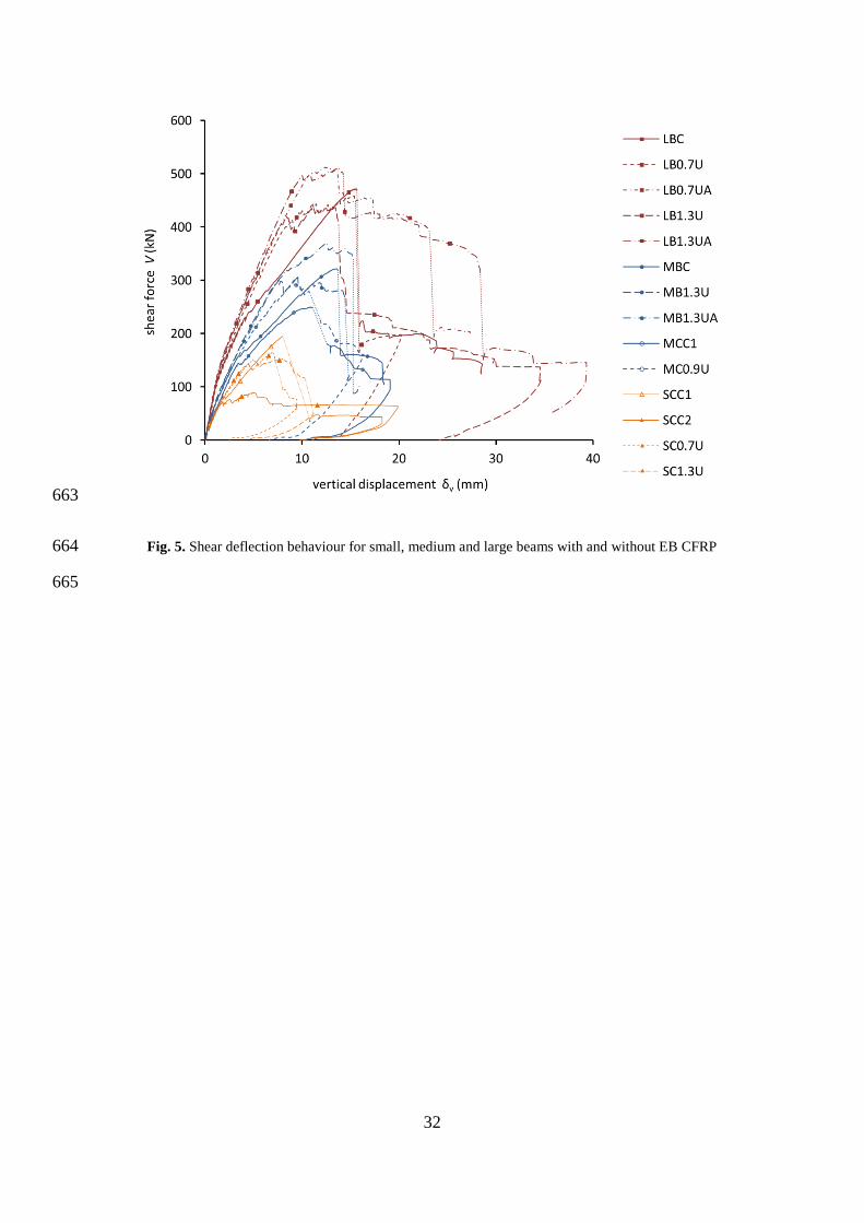
beams than for the unstrengthened control beams, indicating that the externally bonded 293
strengthening delayed the onset of yield in the transverse steel reinforcement. 294
295
13
Fig. 4 shows the failure modes of the unstrengthened control beams, and of the strengthened 296
beams after testing and removal of separated CFRP U-wrap for inspection. A range of critical 297
diagonal crack inclinations were observed. Significant penetration of the flange by the 298
eventual critical diagonal crack prior to peak load was observed for the weaker 299
unstrengthened control beams MCC1, MCC2 and SCC2. The critical diagonal web cracks in 300
the ‘stronger’ control beams LBC, MBC and SCC1 were quite shallow, with an inclination β 301
of approximately 22-23° to the longitudinal axis of the beam. Note that a line drawn platen-302
to-platen would have an inclination of 21.8° which is also the minimum strut inclination 303
permitted by the EC2 variable inclination strut model (BSI 2004). The critical diagonal web 304
cracks in the weakest control beams MCC2 and SCC2 were inclined at approximately 45°, 305
which is also the maximum strut inclination permitted by the EC2 variable inclination strut 306
model (BSI 2004). The critical diagonal web crack in beam MCC1 developed at an 307
intermediate inclination of approximately 31°. The CFRP strengthened beams, which could 308
only be inspected after testing, showed evidence of critical diagonal web cracking at an 309
inclination of approximately 37° in most cases. These observations suggest that the 310
inclination of critical diagonal web cracking can vary considerably in otherwise-similar 311
unstrengthened T-beams. Although a relationship between critical diagonal web crack 312
inclination and shear capacity is indicated, it is unclear whether variation of the web crack 313
inclination is itself a cause of a change in capacity, or a consequence of variability in some 314
other load resisting system(s). The presence of externally bonded CFRP strengthening 315
appears to be associated with reduced variability in both critical diagonal web crack 316
inclination and shear capacity, for the beams considered here. 317
318
Shear-deflection behaviour 319
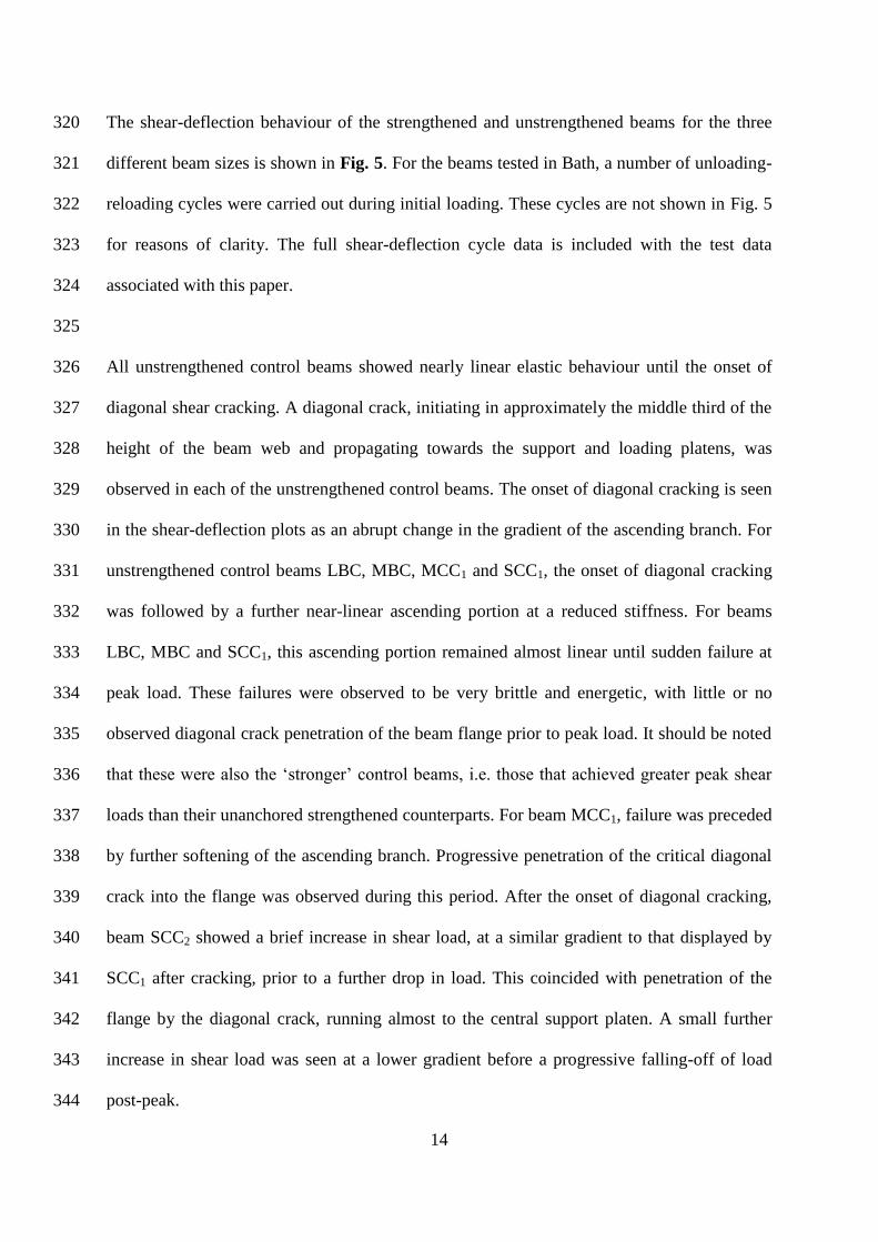
14
The shear-deflection behaviour of the strengthened and unstrengthened beams for the three 320
different beam sizes is shown in Fig. 5. For the beams tested in Bath, a number of unloading-321
reloading cycles were carried out during initial loading. These cycles are not shown in Fig. 5 322
for reasons of clarity. The full shear-deflection cycle data is included with the test data 323
associated with this paper. 324
325
All unstrengthened control beams showed nearly linear elastic behaviour until the onset of 326
diagonal shear cracking. A diagonal crack, initiating in approximately the middle third of the 327
height of the beam web and propagating towards the support and loading platens, was 328
observed in each of the unstrengthened control beams. The onset of diagonal cracking is seen 329
in the shear-deflection plots as an abrupt change in the gradient of the ascending branch. For 330
unstrengthened control beams LBC, MBC, MCC1 and SCC1, the onset of diagonal cracking 331
was followed by a further near-linear ascending portion at a reduced stiffness. For beams 332
LBC, MBC and SCC1, this ascending portion remained almost linear until sudden failure at 333
peak load. These failures were observed to be very brittle and energetic, with little or no 334
observed diagonal crack penetration of the beam flange prior to peak load. It should be noted 335
that these were also the ‘stronger’ control beams, i.e. those that achieved greater peak shear 336
loads than their unanchored strengthened counterparts. For beam MCC1, failure was preceded 337
by further softening of the ascending branch. Progressive penetration of the critical diagonal 338
crack into the flange was observed during this period. After the onset of diagonal cracking, 339
beam SCC2 showed a brief increase in shear load, at a similar gradient to that displayed by 340
SCC1 after cracking, prior to a further drop in load. This coincided with penetration of the 341
flange by the diagonal crack, running almost to the central support platen. A small further 342
increase in shear load was seen at a lower gradient before a progressive falling-off of load 343
post-peak. 344
15
345
All strengthened beams showed a similar pattern of shear-deflection behaviour. Beams with 346
one and two layers of EB CFRP U-wrap appeared to behave similarly. The beams with 347
unanchored CFRP displayed near linear elastic shear-deflection behaviour until 348
approximately twice the load associated with the onset of diagonal cracking for the 349
corresponding control beam(s). This indicates that the onset of diagonal cracking was 350
significantly delayed or inhibited by the EB CFRP. The faltering shear-deflection behaviour 351
observed at or close to peak load corresponds to the observed progressive separation of the 352
EB CFRP sheets from the main web concrete. The beams with anchored CFRP displayed 353
similar shear deflection behaviour to the beams with unanchored CFRP but the peak loads 354
associated with separation of the CFRP were higher than for the unanchored specimens. Post-355
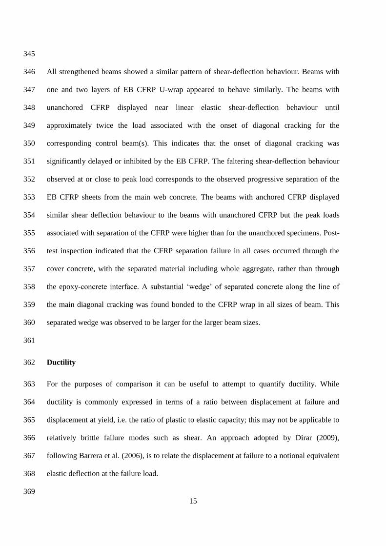
test inspection indicated that the CFRP separation failure in all cases occurred through the 356
cover concrete, with the separated material including whole aggregate, rather than through 357
the epoxy-concrete interface. A substantial ‘wedge’ of separated concrete along the line of 358
the main diagonal cracking was found bonded to the CFRP wrap in all sizes of beam. This 359
separated wedge was observed to be larger for the larger beam sizes. 360
361
Ductility 362
For the purposes of comparison it can be useful to attempt to quantify ductility. While 363
ductility is commonly expressed in terms of a ratio between displacement at failure and 364
displacement at yield, i.e. the ratio of plastic to elastic capacity; this may not be applicable to 365
relatively brittle failure modes such as shear. An approach adopted by Dirar (2009), 366
following Barrera et al. (2006), is to relate the displacement at failure to a notional equivalent 367
elastic deflection at the failure load. 368
369
16
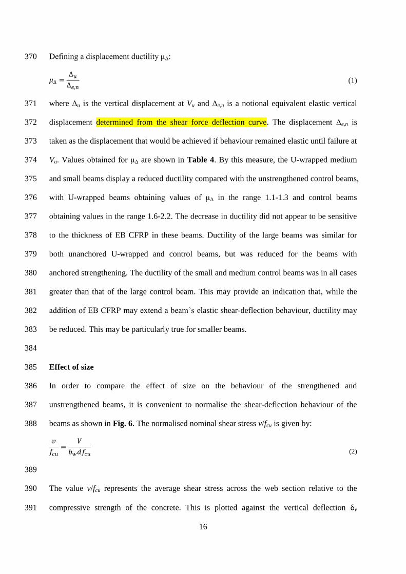
Defining a displacement ductility μΔ: 370
𝜇∆ =Δ𝑢Δ𝑒,𝑛
(1)
where Δu is the vertical displacement at Vu and Δe,n is a notional equivalent elastic vertical 371
displacement determined from the shear force deflection curve. The displacement Δe,n is 372
taken as the displacement that would be achieved if behaviour remained elastic until failure at 373
Vu. Values obtained for μΔ are shown in Table 4. By this measure, the U-wrapped medium 374
and small beams display a reduced ductility compared with the unstrengthened control beams, 375
with U-wrapped beams obtaining values of μΔ in the range 1.1-1.3 and control beams 376
obtaining values in the range 1.6-2.2. The decrease in ductility did not appear to be sensitive 377
to the thickness of EB CFRP in these beams. Ductility of the large beams was similar for 378
both unanchored U-wrapped and control beams, but was reduced for the beams with 379
anchored strengthening. The ductility of the small and medium control beams was in all cases 380
greater than that of the large control beam. This may provide an indication that, while the 381
addition of EB CFRP may extend a beam’s elastic shear-deflection behaviour, ductility may 382
be reduced. This may be particularly true for smaller beams. 383
384
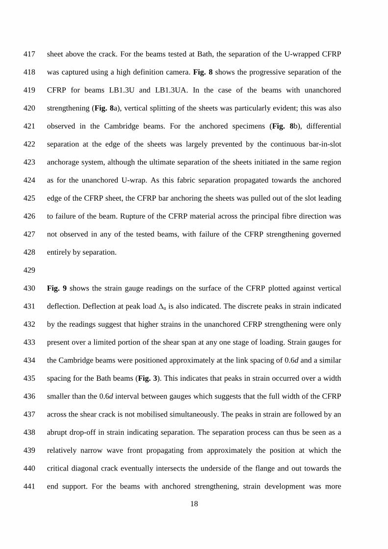
Effect of size 385
In order to compare the effect of size on the behaviour of the strengthened and 386
unstrengthened beams, it is convenient to normalise the shear-deflection behaviour of the 387
beams as shown in Fig. 6. The normalised nominal shear stress v/fcu is given by: 388
𝑣
𝑓𝑐𝑢=
𝑉
𝑏𝑤𝑑𝑓𝑐𝑢
(2)
389
The value v/fcu represents the average shear stress across the web section relative to the 390
compressive strength of the concrete. This is plotted against the vertical deflection δv 391
17
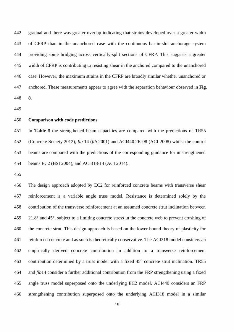
normalised by effective depth d. Fig. 6 shows that the normalised ‘stiffness’ of the medium 392
and large control beams is similar but that the small control beams are stiffer, both before and 393
after the onset of diagonal cracking. Fig. 6 also indicates that the small beams strengthened 394
with unanchored CFRP have a greater normalised stiffness than the medium and large beams 395
strengthened with unanchored CFRP, although to a lesser extent than for the unstrengthened 396
control beams. This difference in stiffness may be at least partially attributed to differences in 397
longitudinal reinforcement ratio (Table 1). 398
399
Fig. 7 plots the peak shear stress vu (Table 1) normalised by fcu1/2
against the natural log of d. 400
The dotted line indicates the gradient of the trend predicted by linear fracture mechanics for 401
the size effect on shear in concrete (Yu & Bazant 2011). The pattern of results indicated both 402
by the ‘stronger’ control beams, and by the strengthened beams is not incompatible with this 403
trend. The similarity of the apparent size effect for both the ‘stronger’ control beams and the 404
strengthened beams indicates that behaviour in the strengthened cases may have been 405
dominated by the underlying reinforced concrete beam. The absence of the same trend in the 406
weaker unstrengthened beams, particularly beam SCC2, indicates a different failure mode; 407
with failure not precipitated by sudden fracture of the concrete. This is compatible with the 408
observed, less brittle and less energetic failure mode of beam SCC2 (Table 4). A size effect 409
relating to the effectiveness of the EB CFRP strengthening is not apparent. This is in contrast 410
with the clear size effect in EB FRP strengthening reported for rectangular beams of similar 411
depth to those tested in this series (Leung et al. 2007). 412
413
CFRP behaviour 414
CFRP behaviour was characterised in all cases by progressive separation of the CFRP above 415
the critical diagonal crack. Peak load was associated with complete separation of the CFRP 416
18
sheet above the crack. For the beams tested at Bath, the separation of the U-wrapped CFRP 417
was captured using a high definition camera. Fig. 8 shows the progressive separation of the 418
CFRP for beams LB1.3U and LB1.3UA. In the case of the beams with unanchored 419
strengthening (Fig. 8a), vertical splitting of the sheets was particularly evident; this was also 420
observed in the Cambridge beams. For the anchored specimens (Fig. 8b), differential 421
separation at the edge of the sheets was largely prevented by the continuous bar-in-slot 422
anchorage system, although the ultimate separation of the sheets initiated in the same region 423
as for the unanchored U-wrap. As this fabric separation propagated towards the anchored 424
edge of the CFRP sheet, the CFRP bar anchoring the sheets was pulled out of the slot leading 425
to failure of the beam. Rupture of the CFRP material across the principal fibre direction was 426
not observed in any of the tested beams, with failure of the CFRP strengthening governed 427
entirely by separation. 428
429
Fig. 9 shows the strain gauge readings on the surface of the CFRP plotted against vertical 430
deflection. Deflection at peak load Δu is also indicated. The discrete peaks in strain indicated 431
by the readings suggest that higher strains in the unanchored CFRP strengthening were only 432
present over a limited portion of the shear span at any one stage of loading. Strain gauges for 433
the Cambridge beams were positioned approximately at the link spacing of 0.6d and a similar 434
spacing for the Bath beams (Fig. 3). This indicates that peaks in strain occurred over a width 435
smaller than the 0.6d interval between gauges which suggests that the full width of the CFRP 436
across the shear crack is not mobilised simultaneously. The peaks in strain are followed by an 437
abrupt drop-off in strain indicating separation. The separation process can thus be seen as a 438
relatively narrow wave front propagating from approximately the position at which the 439
critical diagonal crack eventually intersects the underside of the flange and out towards the 440
end support. For the beams with anchored strengthening, strain development was more 441
19
gradual and there was greater overlap indicating that strains developed over a greater width 442
of CFRP than in the unanchored case with the continuous bar-in-slot anchorage system 443
providing some bridging across vertically-split sections of CFRP. This suggests a greater 444
width of CFRP is contributing to resisting shear in the anchored compared to the unanchored 445
case. However, the maximum strains in the CFRP are broadly similar whether unanchored or 446
anchored. These measurements appear to agree with the separation behaviour observed in Fig. 447
8. 448
449
Comparison with code predictions 450
In Table 5 the strengthened beam capacities are compared with the predictions of TR55 451
(Concrete Society 2012), fib 14 (fib 2001) and ACI440.2R-08 (ACI 2008) whilst the control 452
beams are compared with the predictions of the corresponding guidance for unstrengthened 453
beams EC2 (BSI 2004), and ACI318-14 (ACI 2014). 454
455
The design approach adopted by EC2 for reinforced concrete beams with transverse shear 456
reinforcement is a variable angle truss model. Resistance is determined solely by the 457
contribution of the transverse reinforcement at an assumed concrete strut inclination between 458
21.8° and 45°, subject to a limiting concrete stress in the concrete web to prevent crushing of 459
the concrete strut. This design approach is based on the lower bound theory of plasticity for 460
reinforced concrete and as such is theoretically conservative. The ACI318 model considers an 461
empirically derived concrete contribution in addition to a transverse reinforcement 462
contribution determined by a truss model with a fixed 45° concrete strut inclination. TR55 463
and fib14 consider a further additional contribution from the FRP strengthening using a fixed 464
angle truss model superposed onto the underlying EC2 model. ACI440 considers an FRP 465
strengthening contribution superposed onto the underlying ACI318 model in a similar 466
20
manner. Potential for contribution of the T-beam flange to shear resistance is neglected in all 467
cases. 468
469
EC2 and ACI318 under-predict the strength of the control beams despite the setting of 470
explicit safety factors to 1. For the stronger control beams LBC, MBC and SCC1 the 471
predictions are particularly conservative. The predictions for the capacity of the strengthened 472
beams are generally less conservative than those for the unstrengthened beams with the 473
unfactored values predicted by fib14 and ACI440 often being unconservative. Significant 474
variation is seen between the shear capacity predicted by the EC2 and ACI318 for 475
unstrengthened beams; and between TR55, fib14 and ACI440 for strengthened beams. The 476
influence of the presence of the CFRP strengthening on the delayed onset of yield of the 477
internal transverse steel reinforcement is shown by the increase in Vfy (Table 4) for the beams 478
with unanchored and anchored CFRP strengthening compared to the unstrengthened control 479
beams. Potential for interaction between steel and CFRP strains is not considered by TR55, 480
fib14 or ACI440. 481
482
The principal difference between the TR55, fib14 and ACI440 guidance with respect to the 483
FRP strengthening contribution, are the differing models for the determination of the 484
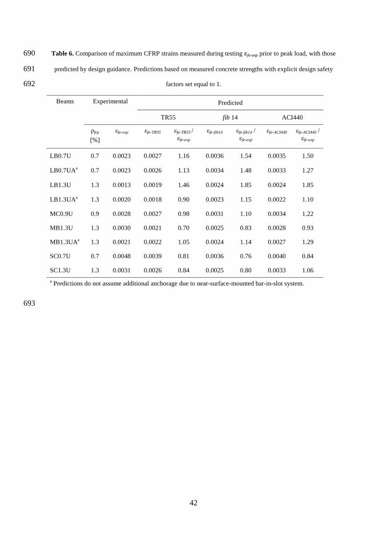
effective FRP strain εfe. As can be seen in Table 6, the effective CFRP strains predicted by 485
TR55, fib 14 and ACI440 were in some cases comparable to the peak CFRP strains εfe-exp 486
measured. However, at peak load these strains appear to have been limited to a width less 487
than the 0.6d link spacing. The width over which the effective strains are considered to be 488
acting in all three models is related to the horizontal projection of the assumed 45° strut 489
inclination, meaning that this width is the same as the lever arm of the idealised FRP-490
concrete truss adopted by each model. For all of the beams tested, the width over which the 491
21
effective CFRP strain is assumed to be mobilised is greater than 0.5d, and in a number of 492
cases greater than 0.6d, according to TR55, fib14 and ACI440. This is evidence of a potential 493
discrepancy between actual CFRP behaviour and that assumed in the guidance. It should be 494
noted that observed crack angles for the strengthened beams were typically lower than the 495
assumed 45° strut inclination for the FRP contribution, but higher than the minimum strut 496
inclination for the unstrengthened capacity contribution given by EC2. It can also be argued 497
that the addition of brittle CFRP material violates the assumption of ductility that is implicit 498
in the lower-bound method of superposition of stress distributions which underpins these 499
design approaches. 500
501
CONCLUSIONS 502
An experimental study of unstrengthened and CFRP-strengthened reinforced concrete T-503
beams was undertaken to investigate the influence of the beam size, anchorage and the 504
percentage of externally bonded U-wrap CFRP reinforcement. Based on the results, the 505
following conclusions can be drawn: 506
A size effect of increasing shear stress capacity with decreasing size was observed for 507
the U-wrapped beams and for the ‘stronger’ unstrengthened beams. This size effect 508
appears to be associated with the behaviour of the underlying reinforced concrete T-509
beam and is broadly compatible with the general trend predicted by fracture 510
mechanics. 511
The variability and significantly greater-than-predicted strength of some of the 512
unstrengthened control beams tested indicates that more accurate assessment of 513
existing slab-on-beam structures may obviate the need for strengthening in some 514
cases. 515
22
Inclinations of the critical diagonal web crack in unstrengthened control beams were 516
observed to range from 22° to 45°. Higher shear capacities were associated with flatter 517
critical diagonal web cracking angles and an absence of crack penetration into the 518
flange prior to failure. Strengthened beams displayed a reduced variation in critical 519
diagonal crack inclination, with an inclination of approximately 37° in most cases. 520
Shear-deflection behaviour indicated that the CFRP U-wrap delayed the onset of 521
significant diagonal cracking in all U-wrapped beams. Stiffer behaviour was observed 522
in U-wrapped beams until near peak load. However, this stiffer behaviour was also 523
associated with reduced ductility compared with unstrengthened control beams. 524
As noted by others, the presence of the CFRP U-wrap delayed the strain development 525
in the internal transverse steel reinforcement, possibly meaning that the steel had not 526
fully yielded until after the CFRP had separated. 527
The relatively small enhancement achieved by the beams with anchored EB CFRP 528
over the stronger unstrengthened control beams indicates that the near-surface-529
mounted anchorage system tested may have the potential to improve CFRP 530
effectiveness, but to a rather limited extent. This increase appears to be due to an 531
increase in the mobilised width of the CFRP rather than the development of increased 532
strains in the CFRP. 533
Comparison of measured versus predicted effective strain levels according to current 534
design guidelines showed that the values may be over- or under-predicted. For the 535
beams with unanchored strengthening, the peak CFRP strains were only observed to 536
occur over a relatively narrow width of CFRP at peak load. This width may be less 537
than the effective width of CFRP assumed to be mobilised by the 45° truss models of 538
TR55, fib14 and ACI440. 539
23
The observed variation in the shear capacity of the unstrengthened control beams was 540
significant in comparison to the magnitude of the enhancement expected from the 541
CFRP strengthening, raising questions as to the appropriateness of the widely-adopted 542
experimental approach for determining the experimental ‘FRP contribution’ on the 543
basis of the tested strength of a single control beam. 544
545
The Authors recognise that the experimental finding that some strengthened beams achieved 546
lower shear capacities than some of their respective control specimens is unusual, although a 547
small number of similar results have been presented previously in the literature by Deniaud & 548
Cheng (2001) and Murphy et al. (2012). Deniaud and Cheng (2001) attribute their result to a 549
sliding shear failure along the dominant diagonal crack. Murphy et al. (2012) attribute their 550
result to the reduction of effective web cross-sectional area due to cover concrete separation 551
with the FRP. 552
553
The reduction in cover concrete due to the separation of the EB CFRP that was observed in 554
the strengthened beams of this test series is likely to have played a role in the reduction of 555
shear capacity of the strengthened beams relative to that of the stronger control beams. This 556
cover separation may have been exacerbated by the particular pattern of web cracking 557
behaviour observed in this test series. Diagonal cracking in the unstrengthened control beams 558
was observed to initiate in approximately the middle third of the shear span and the middle 559
third of the height of the beam web and propagate towards the support and loading platens. 560
Indirect observation indicated that diagonal cracking in the strengthened beams may have 561
also initiated at approximately this position. This suggests that diagonal cracking that initiates 562
in the strengthened web of the beam, rather than as the more commonly observed rotating 563
extension of flexural cracks initiated from the web soffit, may provide an adverse condition 564
24
for EB FRP strengthening. While this condition may be somewhat particular to the tested 565
beam arrangement which had a high longitudinal reinforcement ratio, a low transverse 566
reinforcement ratio with plain mild steel bars, a relatively high concrete strength and a 567
reinforced flange; the implications of these results for the design of EB FRP shear 568
strengthening in general should be considered. 569
570
ACKNOWLEDGEMENTS 571
The authors gratefully acknowledge the help of the laboratory staff of University of Bath and 572
University of Cambridge. The authors would also like to acknowledge the financial support 573
of: the UK Engineering and Physical Sciences Research Council (under grants EPSRC 574
EP/I018921/1 and EP/I018972/1); the Universities of Bath and Cambridge; and the project 575
partners and sponsors – Parsons Brinckerhoff, Tony Gee and Partners LLP, Arup, Highways 576
England, Concrete Repairs Ltd, LG Mouchel and Partners, The Concrete Society, Fyfe 577
Europe S.A., Fibrwrap UK, Hughes Brothers and Ebor Concrete Ltd. 578
579
Additional data related to this publication is available at the University of Bath and the 580
University of Cambridge’s institutional data repositories: [permanent links will be added 581
following review]. 582
583
REFERENCES 584
AASHTO (2008). “Bridging the gap: restoring and rebuilding the nation’s bridges.”, 585
American Association of State Highway Transportation Officials, Washington D.C, 586
USA. 587
25
ACI (American Concrete Institute) (2008). “Guide for the design and construction of 588
externally bonded FRP systems for strengthening concrete structures”, ACI 440.2R-08, 589
Farmington Hills, USA. 590
ACI (American Concrete Institute) (2014). “Building code requirements for structural 591
concrete and commentary”, ACI 318-14, Farmington Hills, USA. 592
Bakis, C. E., Bank, L. C., Brown, V. L., Cosenza, E, Davalos, J. F., Lesko, J. J., Machida, A., 593
Rizkalla, S. H., & Triantafillou, T. C. (2002). “Fiber-reinforced polymer composites for 594
construction – State-of-the-art review”, ASCE Journal of Composites for Construction, 595
6, 73-87. 596
Barrera, A. C., Bonet, J. L., Romero, M. L., Fernandez, M. A., and Miguel, P. F., (2006). 597
“Analysis of ductility in normal strength concrete and high strength concrete columns”, 598
Proceedings of the 2nd fib International Congress, ID 3-7 599
Bousselham, A. & Chaallal, O. (2006a). “Behavior of reinforced concrete T-beams 600
strengthened in shear with carbon fiber-reinforced polymer—an experimental study.”, 601
ACI Structural Journal, 103(3), 339-347. 602
BSI (2004). “Design of concrete structures: general rules and rules for buildings.”, EN 1992-603
1-1:2004, BSI, London, UK. 604
BSI (2005). “Specification for carbon steel bars for the reinforcement of concrete.”, BS 4449: 605
2005, BSI, London, UK. 606
Concrete Society (2012). “Design guidance for strengthening concrete structures using fibre 607
composite materials.”, Technical Report No. 55 3rd Ed., The Concrete Society, 608
Camberley, UK. 609
Deniaud, C. & Cheng, J. J. R. (2001). “Shear behavior of reinforced concrete T-beams with 610
externally bonded fiber-reinforced polymer sheets.”, ACI Structural Journal, 98(3), 611
386-394. 612
26
Dirar, S. M. O. H. (2009). Shear Strengthening of Pre-cracked Reinforced Concrete T-Beams 613
Using Carbon Fibre Systems, Doctoral Thesis, University of Cambridge, UK 614
fib (federation internationale du beton) (2001). “Design and use of externally bonded fibre 615
reinforced polymer reinforcement for reinforced concrete structures.”, Bulletin 14, fib 616
Task Group 9.3, Lausanne, Switzerland 617
Hughes Brothers (2011). Carbon Fiber Reinforced Polymer (CFRP) Bar - Aslan 200 series, 618
Hughes Brothers, Inc., Seward, USA 619
Khalifa, A. T., Alkhrdaji, T., Nanni, A. & Lansburg, S. (1999). “Anchorage of surface 620
mounted FRP reinforcement.”, Concrete International: Design and Construction, 621
21(10), 49-54 622
Leung, C.K.Y, Chen, Z. Lee, S., Ng. M., Xu, M. and Tang, J. (2007). “Effect of Size on the 623
Failure of Geometrically Similar Concrete Beams Strengthened in Shear with FRP 624
Strips”, J. Compos. Constr. 11(5), 487-496, 10.1061/(ASCE)1090-625
0268(2007)11:5(487) 626
Middleton, C.R. (2004). “Bridge management and assessment in the UK”, Proceedings of 627
Austroads 5th Bridge Conference, Austroads, Australia, 16. 628
Mofidi, A. & Chaallal, O. (2014). “Effect of steel stirrups on shear resistance gain due to 629
externally bonded fiber-reinforced polymer strips and sheets”, ACI Structural Journal, 630
111(2), 353-361. 631
Mofidi, A., Chaallal, O., Benmokrane, B. & Neale, K. (2012). “Performance of end-632
anchorage systems for RC beams strengthened in shear with epoxy bonded FRP”, 633
ASCE Journal of Composites for Construction, 16(3), 322-331. 634
Murphy, M., Belarbi, A. and Bae, S-W. (2012). “Behaviour of prestressed concrete I-girders 635
strengthened in shear with externally bonded fiber-reinforced-polymer sheets”, PCI 636
Journal, 57(3), 63-82. 637
27
Ozden, S., Atalay, H. M., Akpinar, E., Erdogan, H. & Vulas, Y. Z. (2014). “Shear 638
strengthening of reinforced concrete T-beams with fully or partially bonded fibre-639
reinforced polymer composites”, Structural Concrete, 15(2), 229-239. 640
Pansuk, W. & Sato, Y. (2007). “Shear mechanism of reinforced concrete T-beam with 641
stirrups.”, Journal of Advanced Concrete Technology, 5(3), 395-408. 642
RILEM (2016), Design procedures for the use of composites in strengthening of reinforced 643
concrete structures: RILEM state-of-the-art report of the RILEM Technical Committee 644
234-DUC, C. Pellegrino and J. Sena-Cruz (Eds.), Springer, Netherlands [DOI: 645
10.1007/978-94-017-7336-2] 646
Thun, H., Ohlsson, U. and Elfgren, L. (2006). “Concrete strength in old Swedish concrete 647
bridges”, Nordic Concrete Research, 35(1-2), 47-60. 648
Yu, Q. & Bazant, Z. P. (2011). “Can stirrups suppress size effect on shear strength of RC 649
beams?”, ASCE Journal of Structural Engineering, 137(5), 607-617. 650
28
651
Fig. 1. Test specimens [mm] 652
653
29
654
Fig. 2. CFRP strengthening arrangements 655
656
30
657
Fig. 3. Loading and support conditions, and strain gauge layout 658
659
31
660
Fig. 4. Failure modes, showing critical web shear crack angles β and peak shear Vu. 661
662
32
663
Fig. 5. Shear deflection behaviour for small, medium and large beams with and without EB CFRP 664
665
33
666
Fig. 6. shear stress v normalised by fcu plotted against δv normalised by d 667
668
34
669
Fig. 7. Peak shear stress vu normalised by fcu1/2
plotted against ln d 670
671
35
672
Fig. 8. Progressive separation of the U-wrapped CFRP 673
674
36
675
Fig. 9. CFRP strains measured in strengthened beams. FR5 gauges positioned closest to the central support and 676
FR1 gauges closest to the end support. A detailed strain gauge layout is shown in Fig. 3. 677
678
37
Table 1. Test matrix 679
beam concrete
steel CFRP
fcu
ρsl ρsv
tfrp ρfrp anchor bar
diameter
MPa
% %
mm % mm
LBC 55.0
2.2 0.1
– – –
LB0.7U
60.3
2.2 0.1
0.5 + 0.5 0.7 –
LB0.7UA 55.0 2.2 0.1 0.5 + 0.5 0.7 13
LB1.3U
62.0
2.2 0.1
1.0 + 1.0 1.3 –
LB1.3UA 54.1 2.2 0.1 1.0 + 1.0 1.3 13
MBC
58.9
2.4 0.1
– – –
MCC1 61.4 2.4 0.1 – – –
MCC2 59.7 2.4 0.1 – – –
MC0.9U 61.7 2.4 0.1 1.0 0.9 –
MB1.3U 64.1 2.4 0.1 1.0 + 0.5 1.3 –
MB1.3UA 61.1 2.4 0.1 1.0 + 0.5 1.3 10
SCC1
65.4
3.5 0.1
– – –
SCC2
59.0
3.5 0.1
– – –
SC0.7U
62.5
3.5 0.1
0.5 0.7 –
SC1.3U 63.2
3.5 0.1
0.5 + 0.5 1.3 –
680
38
Table 2. Steel properties 681
beams bar diameter
db
[mm]
steel grade bar type yield strength
fy
[MPa]
tensile strength
fu
[MPa]
Large
32 B500C Deformed 510a 587
a
16 B500C Deformed 538a 631
a
12 B500C Deformed 518a 586
a
8 S275 Plain 336a 438
a
Medium
Bath
25 B500C Deformed 554a 667
a
12 B500C Deformed 518a 586
a
10 B500C Deformed 538a 625
a
6 S275 Plain 434a 536
a
Medium
Cambridge
25, 12, 10 B500C Deformed 500b ≥ 575
b
6 S275 Plain 570a 637
a
Small 20, 10, 8 B500C Deformed 500
b ≥ 575
b
4 S275 Plain 465a 514
a
a Average values from direct tensile testing
b Characteristic values in accordance with BS 4449: 2005
682
39
Table 3. CFRP composite and constituent properties 683
Efrp
MPa
fu
MPa
εu
%
Epoxy 3180 72 5.0
644 g/m2 fabric 230000 3790 1.7
393 g/m2 fabric 230000 3790 1.7
644 g/m2 fabric – composite
a 95800 986 1.0
393 g/m2 fabric – composite
b 105400 986 1.0
13 mm diameter bar 124000 2068 1.7
10 mm diameter bar 124000 2172 1.7
a nominal thickness per layer 1.00 mm
b nominal thickness per layer 0.51 mm
684
40
Table 4. Summary of test results 685
686
Beams Vu
[kN]
vu
[MPa]
Δu
[mm]
Δe,n
[mm]
μΔ Vfy
[kN]
Δfy
[mm]
Failure mode
LBC 472 2.6 15.6 10.5 1.5 241 4.8 very brittle shear
LB0.7U 458 2.5 15.4 10.9 1.5 409 9.0 fabric separation/shear
LB0.7UA 512 2.8 11.8 10.8 1.1 480 9.5 fabric separation/shear
LB1.3U 437 2.4 13.4 9.8 1.5 396 7.8 fabric separation/shear
LB1.3UA 511 2.8 13.7 10.3 1.3 496 10.7 fabric separation/shear
MBC 322 3.2 13.6 8.6 1.6 163 3.8 very brittle shear
MCC1 250 2.5 10.9 6.0 1.8 159 4.5 brittle shear
MCC2 225 2.2 -- -- -- -- -- brittle shear
MC0.9U 299 2.9 9.2 8.3 1.1 266 7.7 fabric separation/shear
MB1.3U 306 3.0 9.6 8.1 1.2 278 6.7 fabric separation/shear
MB1.3UA 370 3.7 12.6 9.7 1.3 305 7.8 fabric separation/shear
SCC1 195 4.3 8.0 5.0 1.6 98 3.1 very brittle shear
SCC2 89 2.0 5.0 2.2 2.3 68 2.2 shear
SC0.7U 166 3.7 7.0 5.5 1.3 151 5.1 fabric separation/shear
SC1.3U 153 3.4 8.2 5.9 1.4 139 4.6 fabric separation/shear
41
Table 5. Comparison of tested shear strength Vu with the values predicted by design guidance. Explicit design 687
safety factors set equal to 1. 688
Beam Experimental Predicted
EC2 TR55 fib 14 ACI318 ACI440
ρfrp
Vu
VEC2
VEC2
/ Vu
VTR55
VTR55
/ Vu
Vfib14
Vfib14
/ Vu
VACI318
VACI318
/ Vu
VACI440
VACI440
/ Vu
[%] [kN] [kN] [kN] [kN] [kN] [kN]
LBC - 472 126 0.27 - - - - 254 0.54 - -
LB0.7U 0.7 458 - - 322 0.70 494 1.08 - - 563 1.23
LB0.7UA 0.7 512 - - 351 0.69 481 0.92 - - 536 1.05
LB1.3U 1.3 437 - - 394 0.90 630 1.44 - - 684 1.57
LB1.3UA 1.3 511 - - 398 0.78 605 1.18 - - 634 1.24
MBC - 322 93 0.29 - - - - 157 0.53 - -
MCC1 - 250 122 0.49 - - - - 172 0.53 - -
MCC2 - 225 122 0.54 - - - - 175 0.78 - -
MC0.9U 0.9 299 - - 247 0.83 359 1.20 - - 368 1.23
MB1.3U 1.3 306 - - 241 0.79 380 1.24 - - 405 1.32
MB1.3UA 1.3 370 - - 250 0.68 375 1.01 - - 394 1.06
SCC1 – 195 44 0.23 - - - - 73 0.37 - -
SCC2 – 89 44 0.49 - - - - 71 0.80 - -
SC0.7U 0.7 166 - - 102 0.61 137 0.83 - - 149 0.90
SC1.3U 1.3 153 - - 120 0.78 171 1.12 - - 198 1.29
689
42
Table 6. Comparison of maximum CFRP strains measured during testing εfe-exp prior to peak load, with those 690
predicted by design guidance. Predictions based on measured concrete strengths with explicit design safety 691
factors set equal to 1. 692
Beams Experimental Predicted
TR55 fib 14 ACI440
ρfrp
[%]
εfe-exp εfe-TR55 εfe-TR55 /
εfe-exp
εfe-fib14 εfe-fib14 /
εfe-exp
εfe-ACI440 εfe-ACI440 /
εfe-exp
LB0.7U 0.7 0.0023 0.0027 1.16 0.0036 1.54 0.0035 1.50
LB0.7UAa 0.7 0.0023 0.0026 1.13 0.0034 1.48 0.0033 1.27
LB1.3U 1.3 0.0013 0.0019 1.46 0.0024 1.85 0.0024 1.85
LB1.3UAa 1.3 0.0020 0.0018 0.90 0.0023 1.15 0.0022 1.10
MC0.9U 0.9 0.0028 0.0027 0.98 0.0031 1.10 0.0034 1.22
MB1.3U 1.3 0.0030 0.0021 0.70 0.0025 0.83 0.0028 0.93
MB1.3UAa 1.3 0.0021 0.0022 1.05 0.0024 1.14 0.0027 1.29
SC0.7U 0.7 0.0048 0.0039 0.81 0.0036 0.76 0.0040 0.84
SC1.3U 1.3 0.0031 0.0026 0.84 0.0025 0.80 0.0033 1.06
a Predictions do not assume additional anchorage due to near-surface-mounted bar-in-slot system.
693