Embed Size (px)
Citation preview

Engineering NotesExperimental Investigation of Real-Time
Helicopter Weight Estimation
Bradley Taylor∗
Texas A&M University, College Station, Texas 77843
and
Jonathan Rogers†
Georgia Institute of Technology, Atlanta, Georgia 30332
DOI: 10.2514/1.C032449
I. Introduction
M ASS properties are critical parameters that influence stabilityand handling qualities of any flight vehicle. Real-time
knowledge of mass properties is especially useful for helicopterflight, where payload release or acquisition may routinely alter theweight or mass center location in an unknown manner. Examplesinclude a helicopter drawing up water to fight forest fires, a medivachelicopter picking up injured individuals, or a combat helicopterdropping off or picking up supplies or troops.Advanced flight controlsystems can use such information to ensure safe operation of thehelicopter under various flight regimes and to provide feedback forgain scheduling. Additionally, knowledge of the mass propertiesduring flight can reduce maintenance costs by helping to ascertainwhen life-limited parts need to be inspected or replaced in aprecise way.Previous work has been conducted to estimate gross weight of
helicopters during flight. Methods include hover performance charts[1], neural networks [2–4], and corrected moment theory [5]. Mostrecently, Abraham and Costello [6] successfully estimated weightand mass center of a helicopter in a simulation environment bymaking use of an extended Kalman filter. The purpose of this note isto apply the methods of Abraham and Costello to experimentallyestimate the gross weight of a small radio-controlled (R/C) heli-copter, the Align TREX600e. A nonlinear dynamic helicopter modelis developed, and main rotor lift curve slope is estimated usingmaximum likelihood estimation. Flight tests for various helicopterweights are conducted, and it is shown that the gross weight can bereliably estimated in real time during axial maneuvers. The estimatoris also shown to be responsive to instantaneous changes to thehelicopter weight during flight.
II. Helicopter Dynamic Model
A critical component of the proposed estimation framework is amathematical helicopter model that reasonably predicts dynamic
response along the body frame vertical axis to vehicle control inputs.The model’s accuracy in predicting helicopter motion is directlycorrelated to expected accuracy of the gross weight estimates. Thedynamic simulation used for this project is similar to the ARMCOPmodel developed byTalbot et al. [7] andChen [8,9]. The standard six-degree-of-freedom (6DOF) rigid body equations ofmotionmodel theoverall system dynamics, with the resultant force and momentcontaining contributions from the helicopter weight, main rotor, tailrotor, fuselage aerodynamics, and empennage aerodynamics. Rotordynamics are assumed to consist of first-order flapping only, and aquasi-steady flapping approximation is employed. A full descriptionof thismodel can be found in [7]. Note that thismodeling procedure isidentical to that used in the simulation study presented by Abrahamand Costello [6].The particular test helicopter considered for this project is the
ALIGN T-Rex 600e R/C helicopter, shown in Fig. 1. Helicopterparameters are listed in Table 1, and a description of the onboardsensor package is provided in the following section.Model fidelity in descending flight conditions is of special
importance in this experimental study. Descending flight at lowforward speeds is characterized by themain rotor entering vortex ringstate (VRS) or turbulent wake state (TWS). Rotor inflow conditionsin these axial flight states are turbulent due to the interaction of thewake with the main rotor [10]. Although rudimentary inflow modelcorrections for VRS/TWS are available [11], most are low-fidelityand do not provide sufficient combinations of accuracy and run-timeperformance for use in a real-time estimator. As a result, thesecomplex aerodynamic phenomena are not included in the model,and the choice is made to pause weight and mass center estimationwhile in descending, low-speed flight. In reality, this limitation islikely reasonable for practical systems because sustained flightoperations in VRS are typically inadvisable anyway due to safetyconsiderations.
III. Estimation Algorithm
A. Extended Kalman Filter Formulation
Estimation of the 12 rigid body states and the gross weight of thehelicopter is performed using an extended Kalman filter (EKF). TheEKF uses an augmented state vector xA � � x W �T, where xcontains position, attitude, velocity, and angular velocity associatedwith 6DOF motion, and W is the helicopter gross weight. The EKFuses the nonlinear helicopter dynamic model for propagation ofsystem dynamics between measurements. Numerical linearizationof the model is performed during each measurement update aboutthe current state vector using central finite differencing, whilelinearization of themeasurement equations is performed analytically.A detailed description of the generic EKF algorithm is provided in[12], and a flowchart summarizing the EKF process for this study ispresented in Fig. 2. Further details of the estimation algorithm areomitted here for brevity but can be found in [6].
B. Extended Kalman Filter Modifications for TurbulentWake Conditions
Because of modeling difficulties in VRS/TWS, estimation of thegross weight is held constant at the last computed estimate while thehelicopter is descending in low-speed forward flight. It is determinedthat the helicopter is in a descending state by use of a moving averagefilter applied to the body-frame vertical velocity w. To preventestimation of the weight during low forward speed descents, thefollowing constraints are applied to the linearized equations ofmotion:
Presented as Paper 2013-0473 at the AIAA Aerospace Sciences Meeting,Grapevine, TX, 7–10 January 2013; received 28May 2013; revision received18October 2013; accepted for publication 29October 2013; published online26 March 2014. Copyright © 2013 by the American Institute of Aeronauticsand Astronautics, Inc. All rights reserved. Copies of this paper may be madefor personal or internal use, on condition that the copier pay the $10.00 per-copy fee to the Copyright Clearance Center, Inc., 222 Rosewood Drive,Danvers, MA 01923; include the code 1542-3868/14 and $10.00 incorrespondence with the CCC.
*Graduate Research Assistant, Department of Aerospace Engineering.Member AIAA.
†Assistant Professor, Woodruff School of Mechanical Engineering.Member AIAA.
AIAA Early Edition / 1
JOURNAL OF AIRCRAFT
Dow
nloa
ded
by G
EO
RG
IA I
NST
OF
TE
CH
NO
LO
GY
on
Mar
ch 2
6, 2
014
| http
://ar
c.ai
aa.o
rg |
DO
I: 1
0.25
14/1
.C03
2449

∂xi∂W� 0;
∂W∂xi� 0; i � 1 : : : 12 (1)
where xi is the ith element of the rigid body state vector x.Enforcing these constraints prevents the filter from updating the
gross weight estimate and causes the uncertainty in the estimate ofWto grow until the helicopter returns to a nondescending flightcondition. Additionally, during descending flight, the process noiseassociatedwithW is decreased to prevent rapid growth in the estimateuncertainty.
C. Measurements
Measurement data are collected onboard the helicopter usingan ArduPilot Mega 2.0 sensor package and data-acquisition system.The board includes a GPS antenna, three-axis magnetometer, three-axis accelerometer, three-axis gyro, and barometric pressure sensor.Data from these sensors are combined through standard filteringalgorithms to produce direct measurements of position, orientation,and angular velocity. Body-framevelocity components are computedkinematically using GPS measurements, barometer measurements,and orientation feedback assuming zero wind.GPS measurements are recorded at about 5 Hz and all other
measurements at about 30 Hz. It is anticipated that practical imple-mentations of this estimator in aircraft avionics systems would haveaccess to position and orientation data at rates of 20 to 30 Hz or fasterusing coupled GPS-Inertial Navigation System (INS) packages, andthus resampling of flight data is performed in these experiments toprovide a full state estimate at an update rate of 30 Hz.
IV. System Identification
Accuracy of gross weight estimation depends heavily on accuracyof the system dynamic model. Thus, system identification is anecessary first step in estimator design. Several important parametersin the helicopter model cannot be easily measured; thus, a systemidentification algorithm must be developed that can derive accurateparameter estimates from flight test data.
To this end, a maximum likelihood estimation (MLE) algorithm isformulated for nonlinear helicopter parameter identification [12,13].The goal of MLE is to maximize the likelihood function associatedwith a stochastic plant model given observed measurement data.MLE can be instantiated for nonlinear systems through optimizationof a cost function over the model parameter set of interest. Define acost function given by [13]:
J�p� � 1
2
XN
k�1� ~yk − yk�TR−1� ~yk − yk� (2)
where p is the vector of model parameters to be estimated, ~yk is themeasurement vector at time step k, and yk is the measurementpredicted by the dynamic model at time step k for a given value of p.This formulation assumes thatmeasurement noise can be representedby a zero-mean Gaussian white noise process with covariance R.Equation (2) can beminimized to determine themost likely value ofpusing any number of minimization algorithms. For these tests,estimation of the helicopter parameters is performed using theMatlab“fmincon” constrained minimization function. A summary of theMLE process is presented in Fig. 3.The parameter of primary interest in these studies is the main rotor
lift curve slopeCLαMRbecause this parameter is particularly critical in
theweight estimation process due to its effect on axial control power.To estimate CLαMR
, measurements were collected for hover, steadyclimb, and steady descent flight conditions. To promote estimatorconvergence, themodel was constrained during estimation to vertical(axial) motion, and all other motion was restricted in the modeldynamics. As a result, the following dynamic conditions wereimposed:
_x � 0; _y � 0
_u � 0; _v � 0
_ϕ � 0; _θ � 0; _ψ � 0
_p � 0; _q � 0; _r � 0
Additionally, this parameter was estimated onlywith respect to errorsin the altitude and climb rate measurements, resulting in an outputvector
~y � � z _z �T
Although there are numerous additional parameters required for thenonlinearmodel,most have little effect on thevehicle dynamics in theaxial flight conditions studied here. Therefore, reasonable valueswere assumed for these parameters based on measured data andARMCOP approximations. It was confirmed through extensivetesting that estimator performance was relatively insensitive to theirchosen values.
V. Results
A. System Identification Results
The MLE algorithm was used to estimate main rotor lift curveslope CLαMR
using flight test data obtained from three types of axialflight sequences: hover flight only, hover and steady climb only, andhover, steady climb, and steady descent. Numerous data sets werecollected to minimize estimation error due to random perturbationssuch as winds. Figure 4 displays convergence to the CLαMR
estimatefor these three flight sequences for example data sets. Figures 5 and 6show plots of altitude, climb rate and control inputs comparingselected measurements and simulated trajectories using the CLαMRestimates in Fig. 4. Figure 5, from a hover and climb sequence, showsthat estimation results from hover and climbing flight produce a closetrajectorymatch betweenmeasurements andmodel predictions. Notethat results for pure hovering flight yielded similar trajectorymatching and are not shown. However, Fig. 6 shows that the optimalCLαMR
obtained from flight sequences consisting of hover, climb, and
Fig. 1 ALIGN T-Rex 600e R/C helicopter.
Table 1 ALIGN T-Rex 600e nominal parameters
Main rotor radius 2.21 ftMain rotor solidity 0.051Tail rotor radius 0.42 ftTail rotor solidity 0.135Weight 8.15 lbTail rotor distance from main rotor 2.5 ftApproximate main rotor speed 157.1 rad∕sPower source Six-cell LiPo batteryApproximate flight time 10 min
2 AIAA Early Edition / ENGINEERING NOTES
Dow
nloa
ded
by G
EO
RG
IA I
NST
OF
TE
CH
NO
LO
GY
on
Mar
ch 2
6, 2
014
| http
://ar
c.ai
aa.o
rg |
DO
I: 1
0.25
14/1
.C03
2449

descent yields large model deviations from the measurements duringthe descending portion of the flight. This result is attributed tounmodeled effects of the rotor turbulent wake, which cannot becaptured accurately through simplified blade element-momentumtheory models.Note that the estimates in Fig. 4 vary depending on the data set
processed through the MLE algorithm. Therefore, MLE was runmultiple times using various data subsets and for different helicopter
grossweights.An average of the estimated parameterswas taken overall of the flight sequences processed through MLE. Furthermore, itwas desired that the EKF accurately estimate the weight of thehelicopter in at least a hover condition. Therefore, the value used inthe model is the averageCLαMR
estimate from nine different hoveringflight sequences, resulting in CLαMR
� 4.740 rad−1. Note that thestandard deviation of the MLE estimates of CLαMR
in hovering flightwas 0.147 rad−1, or approximately 3.1% of the estimated value. Afull list of the remaining model parameters used in the weightestimator can be found in [14].
B. Control Input Sensitivity to Gross Weight
A sensitivity analysis is performed to characterize the basicdependence of trimmain rotor collective on helicopter weight. Usingblade element-momentum theory (BEMT), an expression can bederived showing that main rotor thrust in hover is proportional to trimcollective according to [7]:
T ∝NB6
ρCLαMRcR�ΩR�2θ0 (3)
In Eq. (3),NB is number of blades, ρ is air density, c is blade chord,Ris blade radius, andΩ is rotor rotation rate. Clearly, this expression is
Fig. 2 Extended Kalman filter flowchart.
Fig. 3 Maximum likelihood estimation flowchart.
0 1 2 3 4 5 6 7 8 94.5
4.6
4.7
4.8
4.9
5
Iterations
Mai
n R
otor
Lif
t Cur
ve S
lope
, 1/r
ad
HoverHover + ClimbHover + Climb + Descent
Fig. 4 Sequence of main rotor lift curve slope estimates from MLEalgorithm.
0 5 10 15 20 25
400
500
Time, s
Alti
tude
, ft
MeasurementsSimulation
0 5 10 15 20 25−5
05
1015
Time, s
Clim
b R
ate,
ft/s
0 5 10 15 20 257
8
9
10
Time, s
Mai
n R
otor
Col
lect
ive,
deg
Fig. 5 Correlation of measured and predicted values using CLαMRestimated from hover and climb sequence.
0 5 10 15 20 25 30 35 40
400
500
Time, s
Alti
tude
, ft
MeasurementsSimulation
0 5 10 15 20 25 30 35 40−20
0
20
Time, s
Clim
b R
ate,
ft/s
0 5 10 15 20 25 30 35 406
8
10
Time, s
Mai
n R
otor
Col
lect
ive,
deg
Fig. 6 Correlation of measured and predicted values using CLαMRestimated from hover, climb, and descent sequence.
AIAA Early Edition / ENGINEERING NOTES 3
Dow
nloa
ded
by G
EO
RG
IA I
NST
OF
TE
CH
NO
LO
GY
on
Mar
ch 2
6, 2
014
| http
://ar
c.ai
aa.o
rg |
DO
I: 1
0.25
14/1
.C03
2449
only valid given several simplifying assumptions, which are detailedin [7]. Furthermore, this linear relationship is preserved only byneglecting any dependence of inflow on trim collective, whichintroduces a small but not insignificant nonlinearity in the thrustresponse. For the helicopter considered in this study, the linearconstant in Eq. (3) relating thrust to collective input computes to3.08 lb∕ deg (for atmospheric conditions observed during testing).This linear relationship can be compared to experimental data todetermine the general nature of the dependence of thrust on mainrotor collective.Figure 7 shows theweight andmain rotor collective input over time
for a spliced data set in which the helicopter weight increases from10 lb to 11 lb to 13 lb. The helicopter hovers at each weight for aperiod of 20 s. The plot of themain rotor collective includes the actualcontrol input over time as well as the mean collective input averagedover the hover period for each individual helicopter weight. Figure 8shows the average trim control inputs versus the helicopter weight,along with a linear least-squares fit of the data. Based on the linearregression, a constant of 1.89 lb∕ deg is obtained relating trimcollective to weight, which is approximately 40% less than thatpredicted by BEMT. Several considerations contribute to thisreduction. First, thrust is the sum of weight and download in hover,and download is not accounted for in the idealized BEMT model.Direct measurements of download are highly impractical and thuscannot be directly subtracted out of the measured data; nevertheless,it can be expected to contribute significantly to the 40% reduction.Furthermore, tip and root losses are not accurately captured in theBEMT model, nor are nonlinear aerodynamics and swirl effects, allof which contribute to reductions in hover performance [10].In spite of these simplifications, the test data verify the nearly linear
relationship predicted by BEMT, with slight nonlinearities inducedby the aforementioned effects including the dependence of inflow ontrim main rotor collective. The conclusion is that a nearly linearrelationship between gross weight and trim collective exists for themodel aircraft in hover, and thus gross weight should be easilyderived from control inputs within a Kalman filter framework.
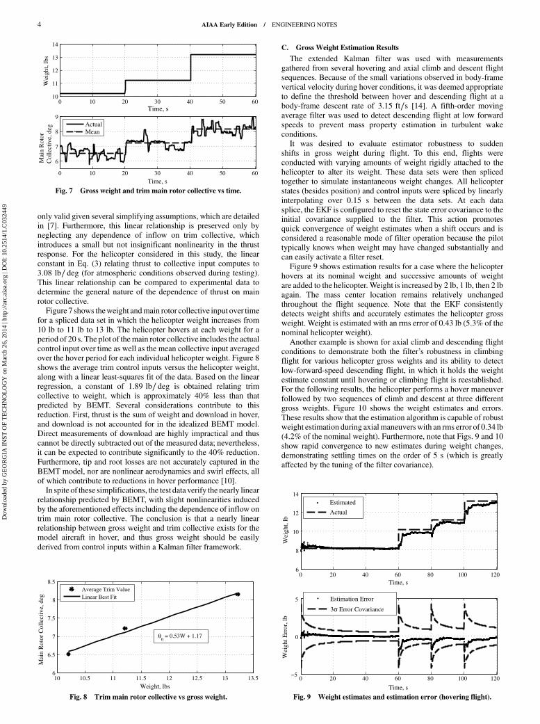
C. Gross Weight Estimation Results
The extended Kalman filter was used with measurementsgathered from several hovering and axial climb and descent flightsequences. Because of the small variations observed in body-framevertical velocity during hover conditions, it was deemed appropriateto define the threshold between hover and descending flight at abody-frame descent rate of 3.15 ft∕s [14]. A fifth-order movingaverage filter was used to detect descending flight at low forwardspeeds to prevent mass property estimation in turbulent wakeconditions.It was desired to evaluate estimator robustness to sudden
shifts in gross weight during flight. To this end, flights wereconducted with varying amounts of weight rigidly attached to thehelicopter to alter its weight. These data sets were then splicedtogether to simulate instantaneous weight changes. All helicopterstates (besides position) and control inputs were spliced by linearlyinterpolating over 0.15 s between the data sets. At each datasplice, the EKF is configured to reset the state error covariance to theinitial covariance supplied to the filter. This action promotesquick convergence of weight estimates when a shift occurs and isconsidered a reasonable mode of filter operation because the pilottypically knows when weight may have changed substantially andcan easily activate a filter reset.Figure 9 shows estimation results for a case where the helicopter
hovers at its nominal weight and successive amounts of weightare added to the helicopter. Weight is increased by 2 lb, 1 lb, then 2 lbagain. The mass center location remains relatively unchangedthroughout the flight sequence. Note that the EKF consistentlydetects weight shifts and accurately estimates the helicopter grossweight. Weight is estimated with an rms error of 0.43 lb (5.3% of thenominal helicopter weight).Another example is shown for axial climb and descending flight
conditions to demonstrate both the filter’s robustness in climbingflight for various helicopter gross weights and its ability to detectlow-forward-speed descending flight, in which it holds the weightestimate constant until hovering or climbing flight is reestablished.For the following results, the helicopter performs a hover maneuverfollowed by two sequences of climb and descent at three differentgross weights. Figure 10 shows the weight estimates and errors.These results show that the estimation algorithm is capable of robustweight estimation during axialmaneuverswith an rms error of 0.34 lb(4.2% of the nominal weight). Furthermore, note that Figs. 9 and 10show rapid convergence to new estimates during weight changes,demonstrating settling times on the order of 5 s (which is greatlyaffected by the tuning of the filter covariance).
0 10 20 30 40 50 6010
11
12
13
14
Time, s
Wei
ght,
lbs
0 10 20 30 40 50 60
6
7
8
9
Time, s
Mai
n R
otor
Col
lect
ive,
deg
ActualMean
Fig. 7 Gross weight and trim main rotor collective vs time.
10 10.5 11 11.5 12 12.5 13 13.56
6.5
7
7.5
8
8.5
Weight, lbs
Mai
n R
otor
Col
lect
ive,
deg
0 = 0.53W + 1.17
Average Trim ValueLinear Best Fit
Fig. 8 Trim main rotor collective vs gross weight.
0 20 40 60 80 100 1206
8
10
12
14
Time, s
Wei
ght,
lb
Estimated
Actual
0 20 40 60 80 100 120−5
0
5
Time, s
Wei
ght E
rror
, lb
Estimation Error
3 Error Covariance
Fig. 9 Weight estimates and estimation error (hovering flight).
4 AIAA Early Edition / ENGINEERING NOTES
Dow
nloa
ded
by G
EO
RG
IA I
NST
OF
TE
CH
NO
LO
GY
on
Mar
ch 2
6, 2
014
| http
://ar
c.ai
aa.o
rg |
DO
I: 1
0.25
14/1
.C03
2449

D. Discussion
The results shown in Figs. 9 and 10 represent a subset of severaltrial flight experiments, which consistently showed that the Kalmanfilter estimator was capable of producing weight estimates withinabout 5% of the actual weight. Settling times proved reasonable, onthe order of several seconds. Because the relationship between thrustand CLαMR
is nearly linear, the identification uncertainty in CLαMRof
approximately 3% maps directly to equivalent uncertainty in weightestimates. This accounts for themajority of estimation error, which ison the order of 4–5%. Additional less significant sources of errorinclude wind effects, error in inflowmodeling, and sensor error fromthe barometric altimeter, which was affected by transient changes ininflow.Flight experiments were also conducted in more general
maneuvering flight conditions; however, performance severelydegraded outside of the axial flight regime.Weight estimates becamepoor in general forward flight and turning maneuvers largely due to alack of model fidelity. The ARMCOPmodel coupled with the quasi-steady rotor flapping assumption is insufficient to capture thelongitudinal and lateral dynamics of the small test helicopter, whichhas a very lightly damped roll and pitch response and strong crosscoupling terms due to a stiff rotor system. System identificationmodels, such as that developed by Cheng et al. [15], may provide amore accurate systemmodel for the purposes of weight estimation ingeneral maneuvering flight.
VI. Conclusions
An experimental investigation of real-time helicopter gross weightestimation was performed using a small R/C helicopter. To capturethe axial dynamic response of the helicopter, flight data were
collected and maximum likelihood estimation applied to identify themain rotor lift curve slope. Flight test sequenceswere performedwithvarious gross weight values to evaluate algorithm performance inaxial flight. Results demonstrate that accurate real-time weightestimates can be obtained with a modified extended Kalman filter inthe axial flight regime, given realistic disturbances and a low-costsensor package.
References
[1] Moffatt, J. G., “HelicopterGrossWeightDetermination fromMonitoredParameters,” U.S. Army Aviation and Troop Command TR-96-D-5,Fort Eustis, VA, May 1996.
[2] Morales, M. A., and Hass, D. J., “Feasibility of Aircraft Gross WeightEstimation Using Artificial Neural Networks,” Proceedings of the
American Helicopter Society 57th Annual Forum, American HelicopterSociety, Inc., Alexandria, VA, May 2001, pp. 1872–1880.
[3] Bi, N. P., Haas, D. J., and McCool, K., “Numerical Study on theRobustness of a Neural NetworkModel for GrossWeight Estimation ofTiltrotor Aircraft,” AIAA Modeling and Simulation Technologies
Conference and Exhibit, AIAA Paper 2005-6112, Aug. 2005.[4] Idan,M., Iosilevskii, G., andNazarov, S., “In-FlightWeight andBalance
Identification using Neural Networks,” Journal of Aircraft, Vol. 41,No. 1, 2004, pp. 137–143.doi:10.2514/1.592
[5] Teal, R. S., Evernham, J. T., Larchuk, T. J., Miller, D. G., Marquith, D.E., White, F., and Deibler, D. T., “Regime Recognition for MH-47EStructural UsageMonitoring,” Proceedings of the American HelicopterSociety 53rd Annual Forum, American Helicopter Society, Inc.,Alexandria, VA, April–May 1997, pp. 1267–1284.
[6] Abraham, M., and Costello, M., “In-Flight Estimation of HelicopterGross Weight and Mass Center Location,” Journal of Aircraft, Vol. 46,No. 3, 2009, pp. 1042–1049.doi:10.2514/1.41018
[7] Talbot, P. D., Tinling, B. E., Decker, W. A., and Chen, R. T. N., “AMathematical Model of a Single Main Rotor Helicopter for PilotedSimulation,” NASA TM-84281, Sept. 1982.
[8] Chen, R. T. N., “A Simplified Rotor System Mathematical Model forPiloted Flight Dynamics Simulation,” NASA TM-78575, May 1979.
[9] Chen, R. T. N., “Effects of Primary Rotor Parameters on FlappingDynamics,” NASA TP-1431, Jan. 1980.
[10] Leishman, J. G., Principles of Helicopter Aerodynamics, 2nd ed.,Cambridge Aerospace Series, Cambridge Univ. Press, NewYork, 2006,pp. 90, 252.
[11] Johnson,W.,Helicopter Theory, Dover, New York, 1994, pp. 106–107.[12] Crassidis, J. L., and Junkins, J. L., Optimal Estimation of Dynamic
Systems, 1st ed., CRC Press, Boca Raton, FL, 2004, pp. 213–219, 285–292.
[13] Iliff, K. W., “Parameter Estimation for Flight Vehicles,” Journal of
Guidance, Control, and Dynamics, Vol. 12, No. 5, 1989, pp. 609–622.doi:10.2514/3.20454
[14] Taylor, B. W., “Experimental Investigation of Helicopter Weight andMass Center Estimation,” M.S. Thesis, Texas A&M Univ., CollegeStation, TX, 2013.
[15] Cheng, R. P., Tischler, M. B., and Schulein, G. J., “R-MAX HelicopterState–Space Model Identification for Hover and Forward-Flight,”Journal of the American Helicopter Society, Vol. 51, No. 2, 2006,pp. 202–210.doi:10.4050/JAHS.51.202
0 50 100 150 200 250 3008
10
12
14
16
Time, s
Wei
ght,
lb
EstimatedActual
0 50 100 150 200 250 300−5
0
5
Time, s
Wei
ght E
rror
, lb
Estimation Error
3 Error Covariance
Fig. 10 Weight estimates and estimation error (axial maneuvers).
AIAA Early Edition / ENGINEERING NOTES 5
Dow
nloa
ded
by G
EO
RG
IA I
NST
OF
TE
CH
NO
LO
GY
on
Mar
ch 2
6, 2
014
| http
://ar
c.ai
aa.o
rg |
DO
I: 1
0.25
14/1
.C03
2449


![Helicopter winching accident Insert document title ... · ATSB Transport Safety Report [Insert Mode] Occurrence Investigation XX-YYYY-#### Final Investigation Helicopter winching](https://img.pdfslide.us/doc/110x75/5e7acd12513e55103a6bbd9c/helicopter-winching-accident-insert-document-title-atsb-transport-safety-report.jpg)