Embed Size (px)
Citation preview

HAL Id: hal-00510526https://hal.archives-ouvertes.fr/hal-00510526
Submitted on 19 Aug 2010
HAL is a multi-disciplinary open accessarchive for the deposit and dissemination of sci-entific research documents, whether they are pub-lished or not. The documents may come fromteaching and research institutions in France orabroad, or from public or private research centers.
L’archive ouverte pluridisciplinaire HAL, estdestinée au dépôt et à la diffusion de documentsscientifiques de niveau recherche, publiés ou non,émanant des établissements d’enseignement et derecherche français ou étrangers, des laboratoirespublics ou privés.
Experimental investigation of face stability of shallowtunnels in sand
Ansgar Kirsch
To cite this version:Ansgar Kirsch. Experimental investigation of face stability of shallow tunnels in sand. W(H)YDOC08 : 3rd international workshop of young doctors in geomechanics, Nov 2008, Champs-sur-Marne,France. pp.61-64. �hal-00510526�
3rd International Workshop of Young Doctors in Geomechanics - W(H)YDOC 08 ereira, De Gennaro & Delage (eds) 2008, ENPC, Champs-sur-Marne
EXPERIMENTAL INVESTIGATION OF FACE STABILITY OF SHALLOW TUNNELS IN SAND
Ansgar Kirsch ([email protected]) Division of Geotechnical Engineering and Tunnelling, University of Innsbruck, Austria
ABSTRACT. The face stability of shallow tunnels was investigated with small-scale model experiments at single gravity. Aim of the research was to detect the evolution of failure mechanisms in dense and loose soil samples with varying overburden above the tunnel. Moreover, the quality of proposed theoretical/numerical approaches for the determination of a necessary support pressure pf was assessed. The results indicate that pf is independent of overburden and initial density of the soil. The experimental investigation with Particle Image Velocimetry revealed a significant influence of initial density on the evolution of failure mechanisms, though: whereas in dense specimen arching and a propagation of the failure mechanism towards the soil surface could be observed, the loose samples showed a much more diffuse failure zone that did not change its shape throughout the failure process.
1. Motivation
For tunnel construction with slurry or earth-pressure balance shields the necessary support pressure pf must be prescribed to prevent excessive ground movements. For the determination of pf various models have been proposed: • Theoretical (e.g. Horn (1961), Kolymbas (2005), Krause (1987), Léca/Dormieux (1990)) • Numerical (e.g. Ruse/Vermeer (2002,2004), Kamata/Mashimo (2003)) • Experimental (e.g. Chambon/Corté (1994), Plekkenpol et al. (2006), Kamata/Mashimo (2003))
Figure 1. Failure mechanism by Horn. Figure 2. Predictions of the necessary support pressure
Horn’s failure mechanism is shown in Fig. 1: it consists of a prismatic wedge in front of the tunnel face and a vertical chimney of soil above. By equilibrating forces on the wedge an expression for the necessary support force to stabilise the mechanism can be found. The vertical force resulting from the chimney is usually calculated with the silo equation. Unfortunately, the Horn mechanism leaves a number of possible configurations to the user: e.g. the choice of earth pressure coefficients for chimney and wedge, the distribution of earth pressure with depth or the shape of the basal wedge surface.
A simple example served to compare Horn’s mechanism with others from the literature. A tunnel with a diameter D=10 m and an overburden C=10 m was chosen for this purpose. Soil parameters were self-weight γ=18 kN/m³ and cohesion c=0. The normalised support pressure at failure ND:=pf/(γdD) is shown in Fig. 2 for a variation of friction angle ϕ between 25° and 45°. Even for a single ϕ there is a large scatter of model predictions. But where is the true necessary support pressure?
2. Qualitative investigation of face stability
To further assess the quality of proposed models for face stability analysis, the author performed two series of small-scale model experiments. The first series of experiments was conducted in a model box (Fig. 3) with inner dimensions 37.2 x 28.0 x 41.0 (width x depth x height in cm). The problem was
61

modelled in half, cutting vertically through the tunnel axis. Therefore, the tunnel was represented by a half-cylinder of perspex, with an inner diameter of 10 cm and a wall thickness of 4 mm.
Figure 3. Box and model tunnel for the first series of experiments.
An aluminium piston was fitted into the tunnel to support the soil. The piston was mounted on a horizontal steel rod, which was supported by a one-dimensional roller bearing inside the side wall of the box. To trigger collapse of the face, a piston displacement s into the model tunnel was applied by turning a threaded bar and a knob in extension of the piston axis (Fig. 3, right).
For all tests dry sand with a grading between 0.1 mm and 2.0 mm was used (d50=0.58 mm, emin=0.42, emax=0.75). The tests were performed with various C/D-ratios and different initial densities Id. For the first 6.0 mm of piston displacement, increments ∆s=0.25 mm were chosen. After that ∆s was increased to 0.5 mm until a total displacement of 25 mm was reached. After each increment a digital picture of the grain structure was taken.
Figure 4. Evaluation of incremental soil displacements with PIV.
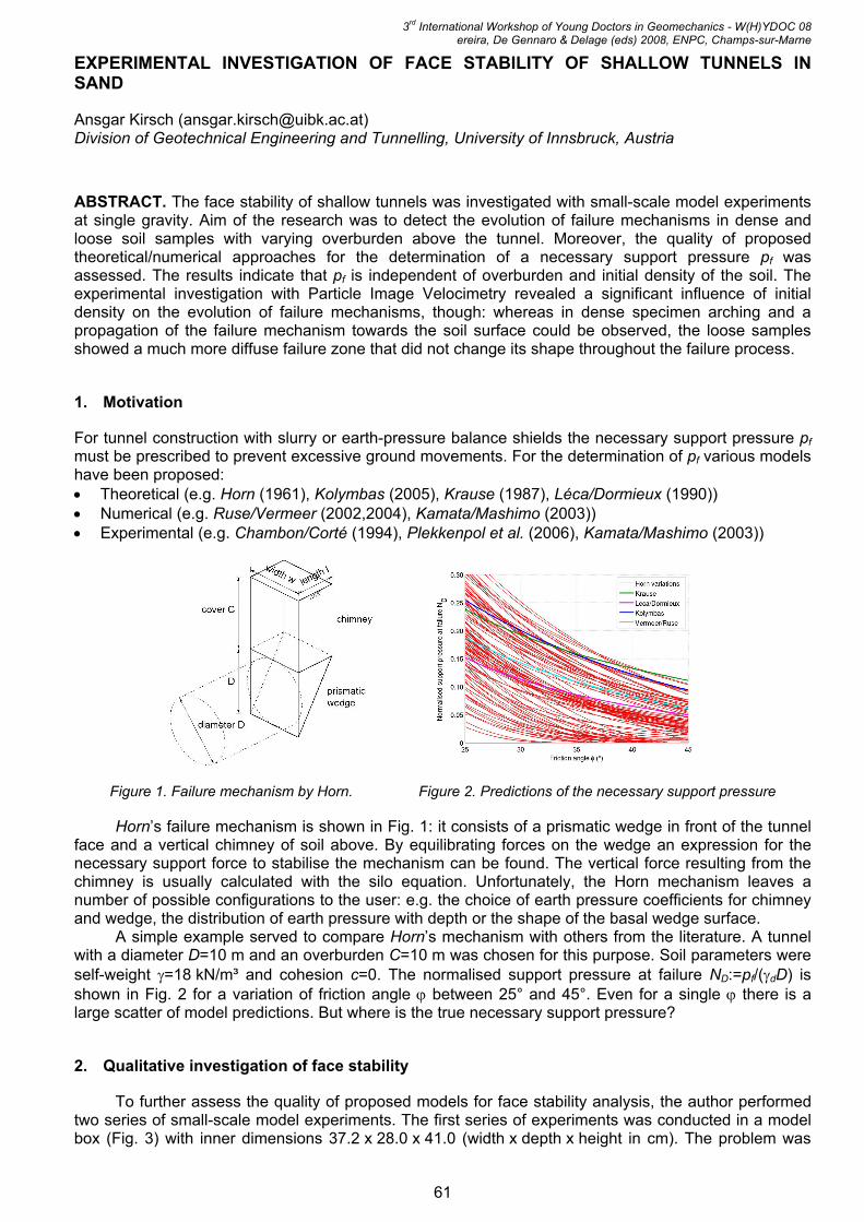
All model tests of the first series were evaluated with Particle Image Velocimetry (PIV), a non-invasive technique that allows the quantitative investigation of plane displacement patterns. The basic idea of PIV is image correlation of interrogation cells in consecutive pictures. These interrogation cells cover a few sand grains and are characterised by a certain distribution of grey or colour values. The primary evaluation results of PIV are vector fields of incremental displacements, which can be visualised as vector plots (Fig. 4, left) or colour plots (Fig. 4, right), in which different lengths of the displacement vectors are represented by different colours.
The PIV analyses showed that the overburden had a negligible influence on the shape and extent of the failure zone for dense soil samples, because the pictures were virtually identical for different overburdens. The impact of density was much more pronounced (Fig. 5): in dense sand a clearly defined failure zone developed in the vicinity of the face and evolved stepwise towards the ground surface. As soon as it reached the ground surface, a chimney-like and a wedge-like part could be distinguished, which resembles the theoretical model by Horn (Fig. 1). On the contrary, for the loose sand soil movements immediately reached up to the ground surface. From the first two or three advance steps onwards, the shape of the failure zone remained practically identical, equal to the one in Fig. 5 (right).
62
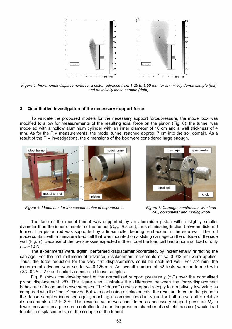
Figure 5. Incremental displacements for a piston advance from 1.25 to 1.50 mm for an initially dense sample (left)
and an initially loose sample (right).
3. Quantitative investigation of the necessary support force
To validate the proposed models for the necessary support force/pressure, the model box was modified to allow for measurements of the resulting axial force on the piston (Fig. 6): the tunnel was modelled with a hollow aluminium cylinder with an inner diameter of 10 cm and a wall thickness of 4 mm. As for the PIV measurements, the model tunnel reached approx. 7 cm into the soil domain. As a result of the PIV investigations, the dimensions of the box were considered large enough.
Figure 6. Model box for the second series of experiments. Figure 7. Carriage construction with load cell, goniometer and turning knob
The face of the model tunnel was supported by an aluminium piston with a slightly smaller diameter than the inner diameter of the tunnel (Ddisk=9.8 cm), thus eliminating friction between disk and tunnel. The piston rod was supported by a linear roller bearing, embedded in the side wall. The rod made contact with a miniature load cell that was mounted on a sliding carriage on the outside of the side wall (Fig. 7). Because of the low stresses expected in the model the load cell had a nominal load of only Fnom=10 N.
The experiments were, again, performed displacement-controlled, by incrementally retracting the carriage. For the first millimetre of advance, displacement increments of ∆s=0.042 mm were applied. Thus, the force reduction for the very first displacements could be captured well. For s>1 mm, the incremental advance was set to ∆s=0.125 mm. An overall number of 52 tests were performed with C/D=0.25 …2.0 and (initially) dense and loose samples.
Fig. 8 shows the development of the normalised support pressure p/(γdD) over the normalised piston displacement s/D. The figure also illustrates the difference between the force-displacement behaviour of loose and dense samples. The “dense” curves dropped steeply to a relatively low value as compared with the “loose” curves. But with continuing displacements, the resultant force on the piston in the dense samples increased again, reaching a common residual value for both curves after relative displacements of 2 to 3 %. This residual value was considered as necessary support pressure ND: a lower pressure (in a pressure-controlled test or in the pressure chamber of a shield machine) would lead to infinite displacements, i.e. the collapse of the tunnel.
63

Figure 8. Development of normalised support pressure for C/D=1.0 and different initial densities.
All results of the 52 tests indicate no influence of overburden on ND. As shown in Fig. 8 also the initial relative density does not influence ND, because the curves of dense and loose samples reach the same residual level.
Comparison with analytical predictions
The results of the force measurements at low stress levels were compared with predictions of the various proposed models presented at the beginning. For this comparison an overburden C/D=1.0 was chosen, cohesion was neglected. The range of experimentally obtained ND values is plotted against the critical friction angle.
Figure 8. Development of normalised support pressure for C/D=1.0 and different initial densities.
Predictions and measurements are of the same order of magnitude; to be more precise, the experimental results lie in the middle of the Horn-model variations. The approaches by Kolymbas and Krause overestimate the experimental results. The upper bound solution by Léca/Dormieux and the empirical approach by Ruse/Vermeer approximate the experimental observations well.
4. References
Horn M. (1961). Horizontaler Erddruck auf senkrechte Abschlussflächen von Tunneln, in Landeskonferenz der ungarischen Tiefbauindustrie (Deutsche Überarbeitung durch STUVA, Düsseldorf).
Kolmybas D. (2005). Tunnelling and Tunnel Mechanics, Springer, Berlin. Krause T. (1987). Schildvortrieb mit flüssigkeits- und erdgestützter Ortsbrust. in Mitteilung des Instituts für
Grundbau und Bodenmechanik, Technische Universität Braunschweig, No. 24. Léca E., Dormieux L. (1990). Upper and lower bound solutions for the face stability of shallow circular tunnels in
frictional material. Géotechnique, 40(4): 581-606. Ruse N.M. (2004). Räumliche Betrachtung der Standsicherheit der Ortsbrust beim Tunnelvortrieb. in Mitteilung
des Instituts für Geotechnik, Universität Stuttgart, No. 51. Vermeer P.A., Ruse N.M., Marcher T. (2002). Tunnel heading stability in drained ground. Felsbau, 20(6): 8-18. Chambon P., Corté J.F. (1994). Shallow tunnels in cohesionless soil: stability of tunnel face, ASCE Journal of
Geotechnical Engineering, 120(7): 1148-1165. Plekkenpol J.W., van der Schrier J.S., Hergarden, H.J. (2006). Shield tunnelling in saturated sand - face support
pressure and soil deformations, in Tunnelling: A Decade of Progress, GeoDelft 1995-2005 (eds. A. Bezuijen, H. van Lottum), Taylor & Francis, London.
64