Embed Size (px)
Citation preview

Instructions for use
Title Experimental study on the unique stability mechanism via miniaturization of jet diffusion flames (microflame) byutilizing preheated air system
Author(s) Fujiwara, Kakeru; Nakamura, Yuji
Citation Combustion And Flame, 160(8): 1373-1380
Issue Date 2013-08
Doc URL http://hdl.handle.net/2115/53016
Type article (author version)
Additional Information There are other files related to this item in HUSCAP. Check the above URL.
File Information CNF_ver20130301_corrected.pdf
Hokkaido University Collection of Scholarly and Academic Papers : HUSCAP

1
Experimental Study on the Unique Stability Mechanism via
Miniaturization of Jet Diffusion Flames (Microflame) by utilizing
Preheated Air System
Kakeru Fujiwara, Yuji Nakamura**
Division of Mechanical and Space Engineering, Hokkaido University
N13 W8, Kita-ku, Sapporo, 060-8628, Japan
Abstract
In this work, we study the near-extinction behavior of micro-jet diffusion (i.e. non-premixed) flame,
so called microflame, formed in a preheated air (up to 1020 K) in order to elucidate the unique and
promising stability mechanism due to miniaturization of the jet diffusion flame. Effects of fuel flow
rate and preheated air temperature on overall flame shape, flame temperature and the burner tip
temperature are examined experimentally. Furthermore, the slight premixing effect on the
near-extinction character is also investigated in order to support the stability mechanism suggested by
this study. Methane is used as fuel and the several kinds of burner material are employed in order to
examine the role of the burner. It turns out that the increasing the preheated air temperature decreases
the limiting minimum flow rate effectively to simulate well the ideal condition of miniaturization of jet
flame. This allows the flame to stay close to the burner and suppress the heat loss to the ambient,
accordingly, the burner tip is substantially heated up. Then, the fuel flowing through the burner
“receives” the heat from the burner (heated by flame) effectively to enhance the reactivity, resulting in
improving the stability. It is also suggested that the endothermic radical-chain reactions are promoted
2
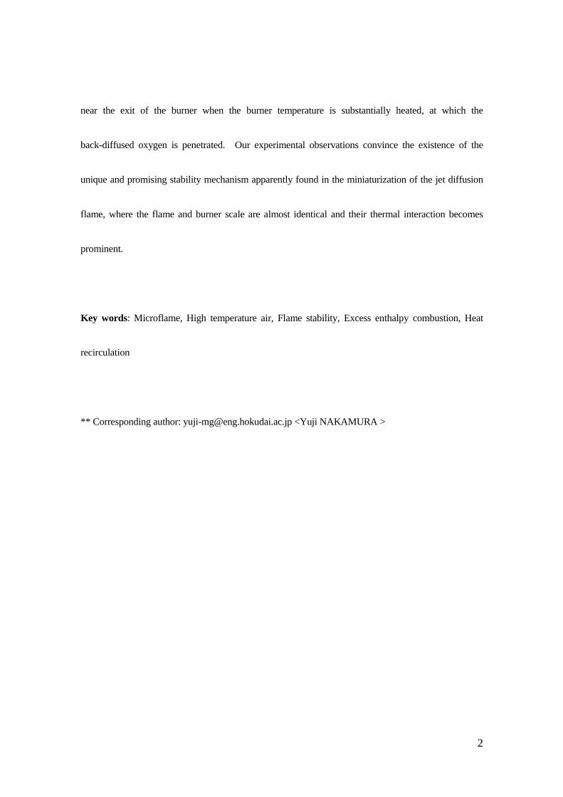
near the exit of the burner when the burner temperature is substantially heated, at which the
back-diffused oxygen is penetrated. Our experimental observations convince the existence of the
unique and promising stability mechanism apparently found in the miniaturization of the jet diffusion
flame, where the flame and burner scale are almost identical and their thermal interaction becomes
prominent.
Key words: Microflame, High temperature air, Flame stability, Excess enthalpy combustion, Heat
recirculation
** Corresponding author: [email protected] <Yuji NAKAMURA >

3
1. Introduction
1.1 Stabilizing Technique for Small-scale Flames
Small-scale combustion becomes a topic in “new-concept combustion” in these days because it
shows unique characteristics. Taking advantage of its size and high-powered density, miniaturizing
flame can be applied to new technologies likely tiny engines and other combustion devices [e.g., 1].
According to the most recent review brought by Maruta [2], however, several unknowns still exist,
especially for its limiting behaviors. There are, therefore, many issues need to be investigated in
terms of the scale effect on the limiting combustion character.
Here, let us consider the possible scale effect on the flame stability. Heat loss to the surroundings
becomes relatively large as compared to a standard-sized flame as the flame scale is reduced, then the
flame gradually loses the stability and is eventually quenched. In this way, it is understood that we
have small-scale limit to sustain the flame. Novel combustion devices have been developed to
overcome the disadvantage to enlarge the stability limit. One example is a Swiss-roll combustor that
consists of two spiral channels with combustion space at the center [3-5]. Its fundamental concept is
based on excess enthalpy combustion proposed by Weinberg [6] which also have been applied to the
porous burner to attain the low-load combustion [7,8]; namely, recirculate the combustion-generated
heat toward the unburned premixed gas in pre-burning process. The channel wall plays a role of heat
transfer medium for the heat recirculation in the case of the Swiss roll combustor. Recently, the

4
fundamental characteristics of the premixed flame in a heated micro channel were studied in the
context of this combustor [9-11], revealing that utilizing such heat recirculation is one of promising
way in miniaturizing combustion devices. Interestingly, all existing combustors/burners utilizing the
heat recirculation for further stabilization have been only considered in the premixed flame, although
the same strategy could also be applied to the diffusion (i.e., non-premixed) flame. More specifically,
the similar stability mechanism would exist also in small-scale diffusion flames, so called microflame
[12-13], in which the flame-burner (wall) interaction becomes prominent. If so, this additional
stabilized mechanism has potential to cover up unknowns in miniaturizing flames as pointed in [2].
This is the motivation of the present study.
1.2 Stability of a Micro-jet Diffusion Flame (Microflame)
Microflame is known as a millimeter-size of diffusion flame formed over a fine needle burner
(inner dia. < 1.0 mm) [12-13]. So far, a number of studies have been conducted in order to elucidate
the stability of the microflame. Nakamura et al. [14] firstly attempted to investigate the effect of
cooled boundary on the flame shape and stability of the microflame, showing the importance of
thermal interaction between the flame and the burner. Later, Matta et al. [15], Nakamura [16-17],
Chen et al., [18], Butler et al. [19] made a different series of studies of micro-jet diffusion flame to
support this issue. Importantly, the most of evidence implies that the burner always act as “heat sink”
5
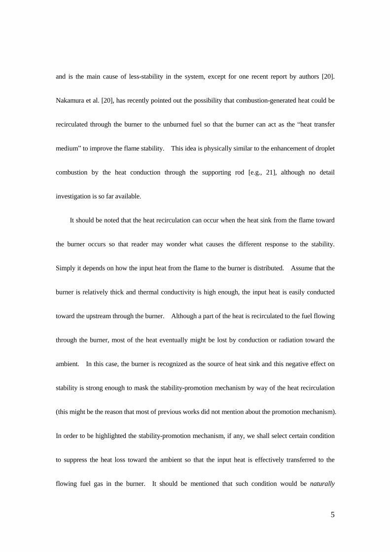
and is the main cause of less-stability in the system, except for one recent report by authors [20].
Nakamura et al. [20], has recently pointed out the possibility that combustion-generated heat could be
recirculated through the burner to the unburned fuel so that the burner can act as the “heat transfer
medium” to improve the flame stability. This idea is physically similar to the enhancement of droplet
combustion by the heat conduction through the supporting rod [e.g., 21], although no detail
investigation is so far available.
It should be noted that the heat recirculation can occur when the heat sink from the flame toward
the burner occurs so that reader may wonder what causes the different response to the stability.
Simply it depends on how the input heat from the flame to the burner is distributed. Assume that the
burner is relatively thick and thermal conductivity is high enough, the input heat is easily conducted
toward the upstream through the burner. Although a part of the heat is recirculated to the fuel flowing
through the burner, most of the heat eventually might be lost by conduction or radiation toward the
ambient. In this case, the burner is recognized as the source of heat sink and this negative effect on
stability is strong enough to mask the stability-promotion mechanism by way of the heat recirculation
(this might be the reason that most of previous works did not mention about the promotion mechanism).
In order to be highlighted the stability-promotion mechanism, if any, we shall select certain condition
to suppress the heat loss toward the ambient so that the input heat is effectively transferred to the
flowing fuel gas in the burner. It should be mentioned that such condition would be naturally
6
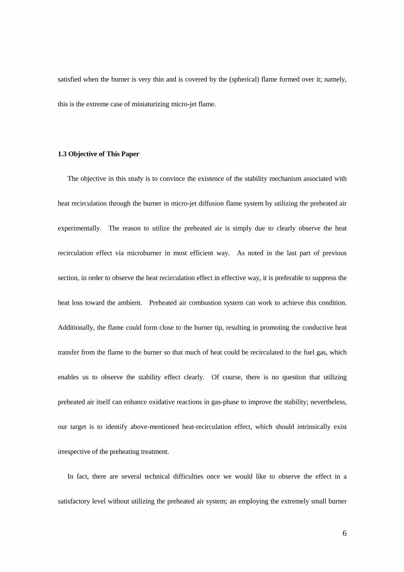
satisfied when the burner is very thin and is covered by the (spherical) flame formed over it; namely,
this is the extreme case of miniaturizing micro-jet flame.
1.3 Objective of This Paper
The objective in this study is to convince the existence of the stability mechanism associated with
heat recirculation through the burner in micro-jet diffusion flame system by utilizing the preheated air
experimentally. The reason to utilize the preheated air is simply due to clearly observe the heat
recirculation effect via microburner in most efficient way. As noted in the last part of previous
section, in order to observe the heat recirculation effect in effective way, it is preferable to suppress the
heat loss toward the ambient. Preheated air combustion system can work to achieve this condition.
Additionally, the flame could form close to the burner tip, resulting in promoting the conductive heat
transfer from the flame to the burner so that much of heat could be recirculated to the fuel gas, which
enables us to observe the stability effect clearly. Of course, there is no question that utilizing
preheated air itself can enhance oxidative reactions in gas-phase to improve the stability; nevertheless,
our target is to identify above-mentioned heat-recirculation effect, which should intrinsically exist
irrespective of the preheating treatment.
In fact, there are several technical difficulties once we would like to observe the effect in a
satisfactory level without utilizing the preheated air system; an employing the extremely small burner

7
(diameter is small and the thickness is thin) with the less-conductive material (so that it can be heated
up easily) is one of simplest candidate. First of all, however, fabricating such tiny burner itself is
difficult. Suppose such “ultra-microburner” is available and used on purpose without utilizing
preheated air system, then it is easy to expect that the temperature at the burner tip could occasionally
increase, eventually the burner tip may “melt” to choke the fuel flow. Controllability is, therefore, not
good so that the systematic study becomes difficult. Utilizing the preheated air can avoid such
potential difficulties, yet enable us to represent the physically-identical condition of extremely
down-scaled jet burner system with better controllability.
In this study, a wide range of preheated air temperature (up to 1020 K) was adopted to examine the
limiting character of near-extinction microflame systematically. Slight premixing effect was also
investigated to understand the limiting character better. After all, the existence of the flame stability
mechanism was ensured in miniaturizing jet diffusion flame, which could be recognized as one of the
unique and promising character of microflame.
2. Experimental method
2.1 Apparatus and Conditions
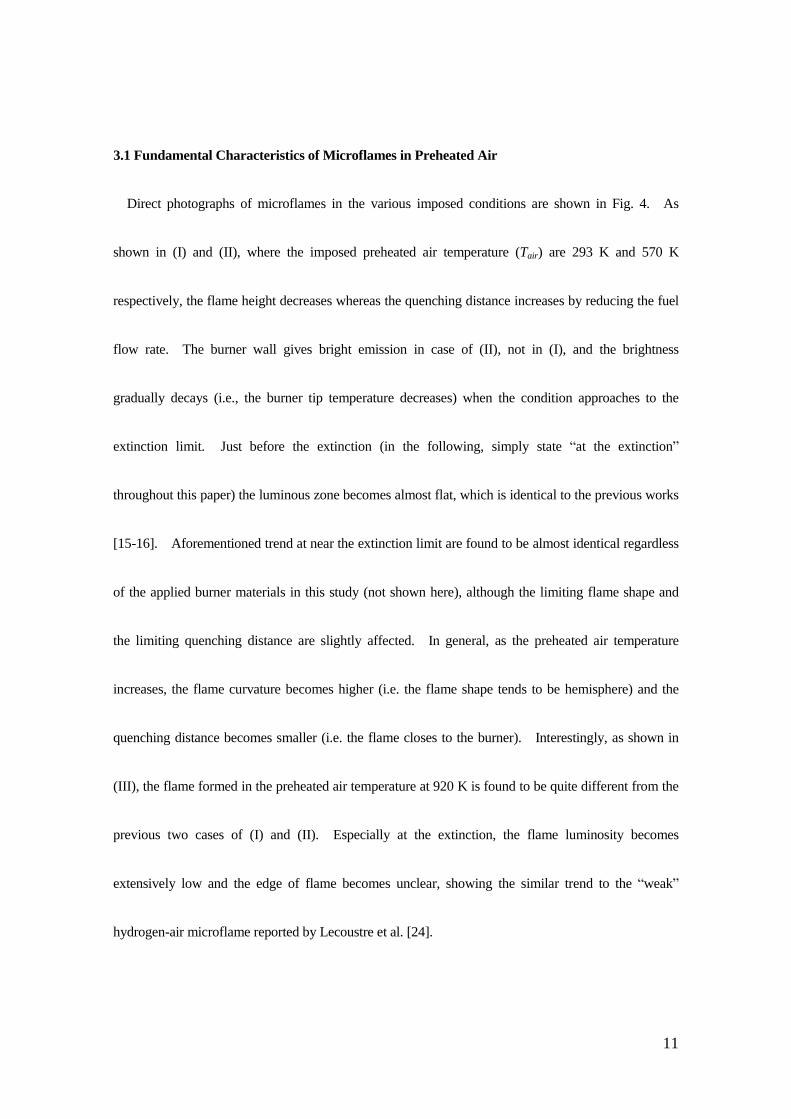
Fig. 1 shows the burner systems schematically. Since the detailed of the preheated air
combustion system utilized in this study can be found in elsewhere [22], the brief description is made

8
here. Co-flow type of burner system was introduced; fuel (methane) was issued from the center
circular-port jet and the preheated air was issued from the outer port. The thermal insulator was set
around the main combustion chamber made of the quartz glass to minimize the heat loss to the ambient.
Volumetric flow rate of the co-flow air was set at a constant (1.0 L/min at a standard state, where
corresponding air velocity was 1.0 cm/s) throughout the study. High-temperature air heated by the
electric heater went through the section of the bed filled with ceramic balls (dia. of 2.0 mm) to
eliminate large eddies and became a spatially uniform in the main chamber. A nickel-chrome (Ni-Cr)
wire was additionally installed in the ceramic ball bath for better control in order to obtain the target air
temperature. The preheated air temperature was measured using a thermocouple (K-type, wire dia.:
0.3 mm, junction dia.: 0.7 mm) and inserted from the top of the chamber. After the preheated air
temperature reached to the target value and the temperature field became steady state, the
thermocouple was removed, instead, the micro burner (inner dia.: 0.8 mm, outer dia.: 1.2 mm) was
inserted from the bottom. The fuel flow rate was controlled by a fine needle valve and measured by a
soap bubble meter (Shimadzu GL Science, 3001-1102: 15 mL of maximum volume tube), and adjusted
to obtain the limiting flames. The reproducibility was carefully checked and it was found that the
uncertainty of the prescribed flow rate was up most 1.0 %. The temperature of the preheated air, Tair
[K] (up to 1020 K), and the fuel flow rate, Vf [mL/min], were considered as main experimental
parameters in this study. Additionally, several kinds of burner material were employed, such as
9
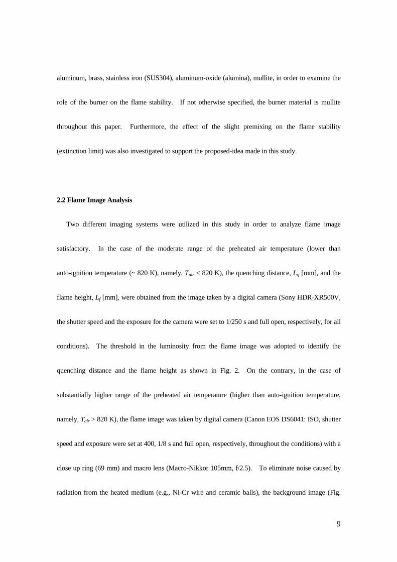
aluminum, brass, stainless iron (SUS304), aluminum-oxide (alumina), mullite, in order to examine the
role of the burner on the flame stability. If not otherwise specified, the burner material is mullite
throughout this paper. Furthermore, the effect of the slight premixing on the flame stability
(extinction limit) was also investigated to support the proposed-idea made in this study.
2.2 Flame Image Analysis
Two different imaging systems were utilized in this study in order to analyze flame image
satisfactory. In the case of the moderate range of the preheated air temperature (lower than
auto-ignition temperature (~ 820 K), namely, Tair < 820 K), the quenching distance, Lq [mm], and the
flame height, Lf [mm], were obtained from the image taken by a digital camera (Sony HDR-XR500V,
the shutter speed and the exposure for the camera were set to 1/250 s and full open, respectively, for all
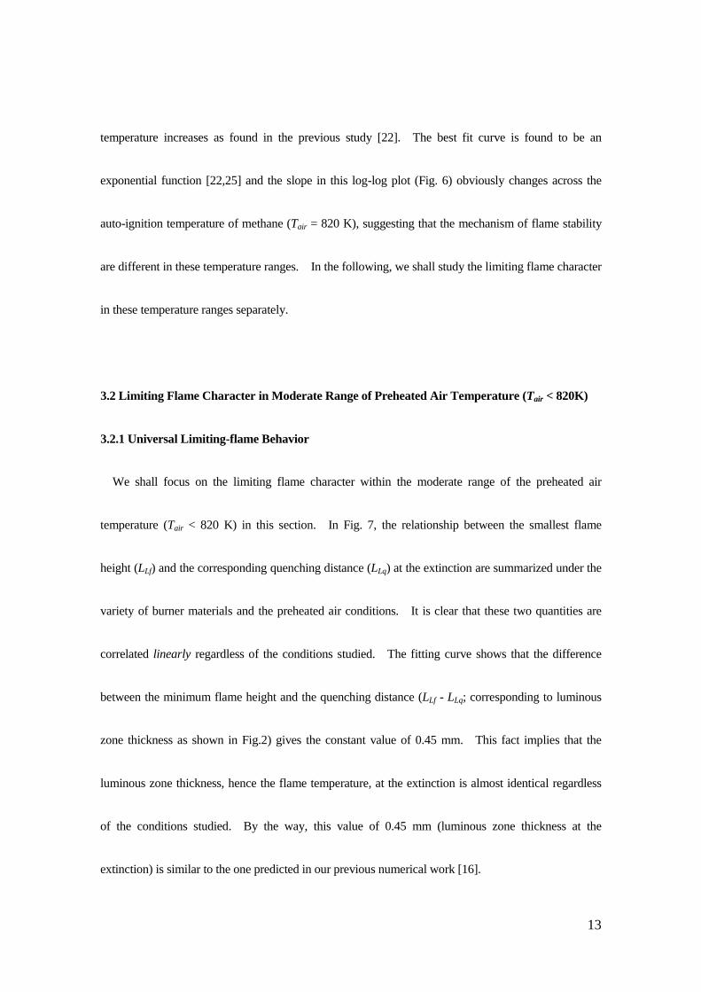
conditions). The threshold in the luminosity from the flame image was adopted to identify the
quenching distance and the flame height as shown in Fig. 2. On the contrary, in the case of
substantially higher range of the preheated air temperature (higher than auto-ignition temperature,
namely, Tair > 820 K), the flame image was taken by digital camera (Canon EOS DS6041: ISO, shutter
speed and exposure were set at 400, 1/8 s and full open, respectively, throughout the conditions) with a
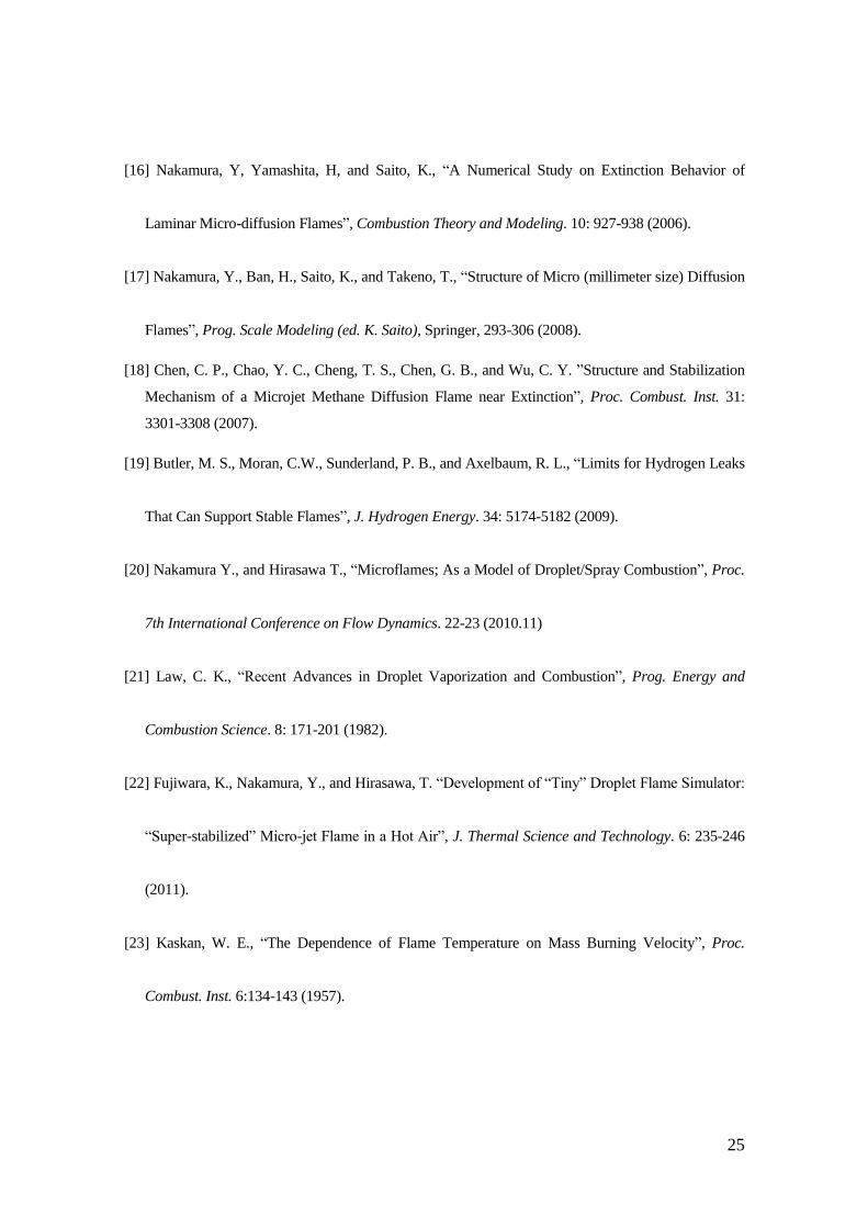
close up ring (69 mm) and macro lens (Macro-Nikkor 105mm, f/2.5). To eliminate noise caused by
radiation from the heated medium (e.g., Ni-Cr wire and ceramic balls), the background image (Fig.
10
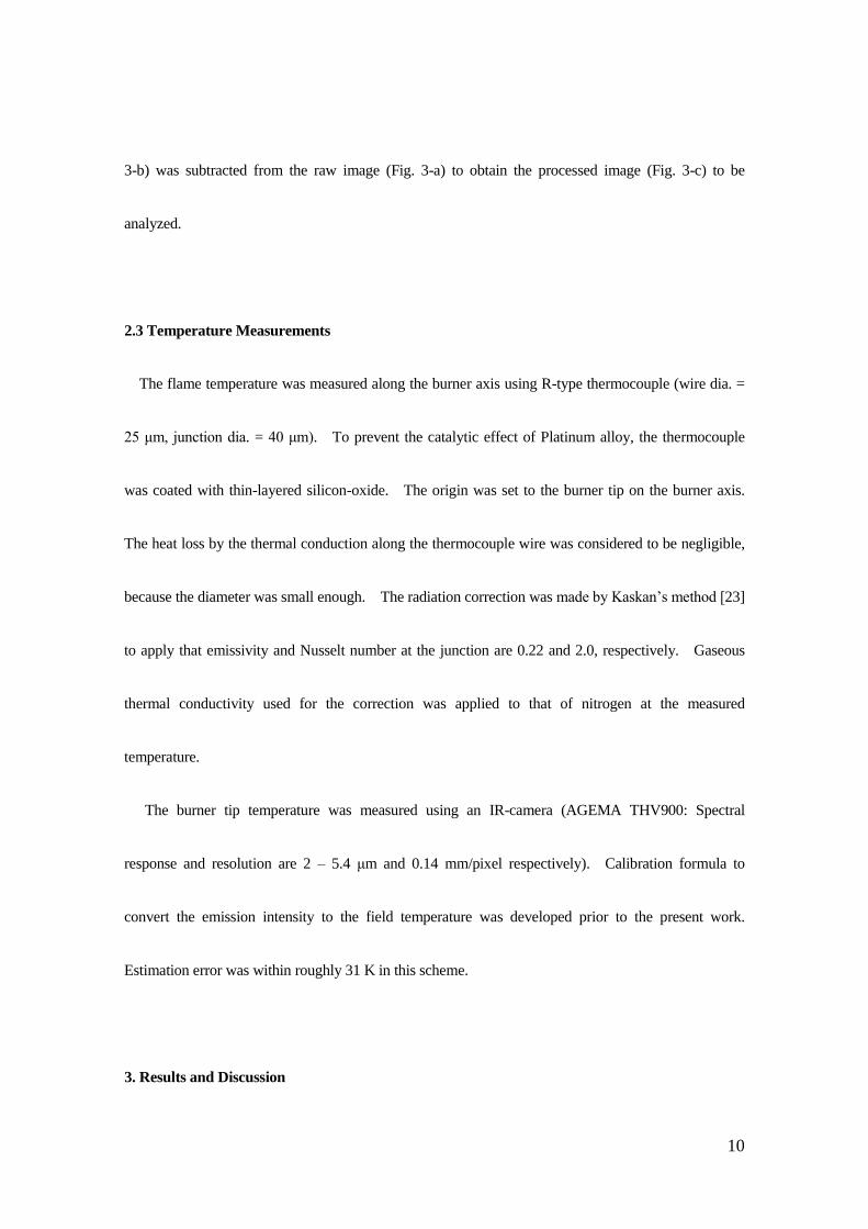
3-b) was subtracted from the raw image (Fig. 3-a) to obtain the processed image (Fig. 3-c) to be
analyzed.
2.3 Temperature Measurements
The flame temperature was measured along the burner axis using R-type thermocouple (wire dia. =
25 μm, junction dia. = 40 μm). To prevent the catalytic effect of Platinum alloy, the thermocouple
was coated with thin-layered silicon-oxide. The origin was set to the burner tip on the burner axis.
The heat loss by the thermal conduction along the thermocouple wire was considered to be negligible,
because the diameter was small enough. The radiation correction was made by Kaskan’s method [23]
to apply that emissivity and Nusselt number at the junction are 0.22 and 2.0, respectively. Gaseous
thermal conductivity used for the correction was applied to that of nitrogen at the measured
temperature.
The burner tip temperature was measured using an IR-camera (AGEMA THV900: Spectral
response and resolution are 2 – 5.4 μm and 0.14 mm/pixel respectively). Calibration formula to
convert the emission intensity to the field temperature was developed prior to the present work.
Estimation error was within roughly 31 K in this scheme.
3. Results and Discussion
11
3.1 Fundamental Characteristics of Microflames in Preheated Air
Direct photographs of microflames in the various imposed conditions are shown in Fig. 4. As
shown in (I) and (II), where the imposed preheated air temperature (Tair) are 293 K and 570 K
respectively, the flame height decreases whereas the quenching distance increases by reducing the fuel
flow rate. The burner wall gives bright emission in case of (II), not in (I), and the brightness
gradually decays (i.e., the burner tip temperature decreases) when the condition approaches to the
extinction limit. Just before the extinction (in the following, simply state “at the extinction”
throughout this paper) the luminous zone becomes almost flat, which is identical to the previous works
[15-16]. Aforementioned trend at near the extinction limit are found to be almost identical regardless
of the applied burner materials in this study (not shown here), although the limiting flame shape and
the limiting quenching distance are slightly affected. In general, as the preheated air temperature
increases, the flame curvature becomes higher (i.e. the flame shape tends to be hemisphere) and the
quenching distance becomes smaller (i.e. the flame closes to the burner). Interestingly, as shown in
(III), the flame formed in the preheated air temperature at 920 K is found to be quite different from the
previous two cases of (I) and (II). Especially at the extinction, the flame luminosity becomes
extensively low and the edge of flame becomes unclear, showing the similar trend to the “weak”
hydrogen-air microflame reported by Lecoustre et al. [24].

12
Figure 5 shows the effect of the thermal conductivity of the burner materials (b) on the minimum
fuel flow rate (VLf, denoting the lowest Vf to attain the extinction) for the case of without preheated air
(Tair =293 K). The minimum fuel flow rate decreases monotonically as the thermal conductivity of
the burner decreases. Burner tip temperature would become higher under such conditions,
accordingly, the stability of microflame is expected to be strongly affected. The sensitivity of the
minimum fuel flow rate is found to be higher in the low-range of thermal conductivity; especially less
than 10 W/(mK), suggesting that the lower thermal conductivity burner is better in regards to improve
the stability. One thing should be noticed that this observed trend with regard to the stability response
against the thermal conductivity seems to contradict to the well-known excess enthalpy combustion
concept [e.g. 3-11]. There must be at least three reasons to explain; the first is to accumulate heat at
the burner tip to increase the temperature to reduce the heat loss from the flame toward the burner, the
second is to accumulate heat at the burner tip to enhance the reaction kernel formed at flame leading
edge, and the third is to accumulate heat at the burner tip to enhance the potential chemical reaction
inside the burner tube (as discussed in Sec. 3.3.3). The observed response of stability against the
thermal conductivity of the material can be recognized as one of unique feature for microflame, i.e.,
diffusion (non-premixed) combustion system in small-scale.
The relationship between the minimum limit of the fuel flow rate (VLf) and the preheated air
temperature (Tair) is depicted in Fig. 6. The stability is clearly improved when the preheated air
13
temperature increases as found in the previous study [22]. The best fit curve is found to be an
exponential function [22,25] and the slope in this log-log plot (Fig. 6) obviously changes across the
auto-ignition temperature of methane (Tair = 820 K), suggesting that the mechanism of flame stability
are different in these temperature ranges. In the following, we shall study the limiting flame character
in these temperature ranges separately.
3.2 Limiting Flame Character in Moderate Range of Preheated Air Temperature (Tair < 820K)
3.2.1 Universal Limiting-flame Behavior
We shall focus on the limiting flame character within the moderate range of the preheated air
temperature (Tair < 820 K) in this section. In Fig. 7, the relationship between the smallest flame
height (LLf) and the corresponding quenching distance (LLq) at the extinction are summarized under the
variety of burner materials and the preheated air conditions. It is clear that these two quantities are
correlated linearly regardless of the conditions studied. The fitting curve shows that the difference
between the minimum flame height and the quenching distance (LLf - LLq; corresponding to luminous
zone thickness as shown in Fig.2) gives the constant value of 0.45 mm. This fact implies that the
luminous zone thickness, hence the flame temperature, at the extinction is almost identical regardless
of the conditions studied. By the way, this value of 0.45 mm (luminous zone thickness at the
extinction) is similar to the one predicted in our previous numerical work [16].

14
3.2.2 Role of Burner as Heat Recirculation Medium
To verify the above-mentioned limiting character of the flames, temperature measurement of the
flame and burner are made. Gas temperature distributions at 293 K and 670 K of the preheated air
temperatures along the axis are shown in Fig. 8. The observed temperature distribution has a single
peak as expected. Temperature gradient toward downstream is found to be rather mild when the
imposed preheated air temperature is low and the ejected fuel flow rate is high, on the contrary, it holds
relatively steep as the preheated air temperature increases and the ejected fuel flow rate is low. Under
these conditions, the flame height (namely the flame scale) becomes smaller, confirming that the
diffusion transport toward the downstream must be taken into account in the analysis of microflame
[e.g. 12]. It is also found that the temperature gradient toward upstream shows less sensitive against
the fuel flow rate, more importantly, the interesting response of the heat flux from the flame toward the
unburned gas at Y = 0 is observed in the present study as shown in Figure 9. Dashed lines, (a) ~ (c),
show the minimum fuel flow rates in the prescribed preheated air temperature conditions. The heat
flux keeps constant against the fuel flow rate and then, slightly increases near extinction limit. One
fact should be noticed that the critical flux at the extinction limit is found to be nearly identical (~ 80
W/mm2) irrespective of the imposed preheated temperature, suggesting that the limiting reaction rate
(as well as the limiting flame temperature) should be also nearly identical. Although only the case of

15
mullite is presented here, as long as the burner is catalytically inert and the same fuel is used, it is
convinced that thermal balance between the burner and the flame should be the major cause of the
extinction. Base on the fact that the different burner material gives different limiting distance
between the flame and burner (see Fig. 7), the limiting heat flux could be adjusted accordingly. In
this sense, it is expected that the above-mentioned scenario would be similarly applied not only to
mullite but also the other materials.
Figure 10 shows how flame temperature (the maximum gas temperature) is varied against the
applied fuel flow rate. Dashed lines, (a) ~ (c), show the minimum fuel flow rates in the prescribed
preheated air temperature conditions. The flame temperature is linearly correlated to the fuel flow
rate and the flame temperature at the extinction is almost identical (~ 1700 K) regardless of the
imposed preheated air temperature. This result is reasonable because the heat fluxes toward the
upstream at the extinction are also nearly identical as shown in Fig. 9, implying that the same
reaction-diffusion balance is established at the extinction irrespective of the imposed preheated air
conditions. Recall that the flame temperature and the critical heat flux at the extinction are nearly
identical regardless of the flame position, the gas temperature at the burner exit should increase
accordingly with the flame closing to the burner to fulfill the observed fact. This is verified in Figure
11 showing the gas temperature at Y = 0 against the imposed fuel flow rate under three preheated air
temperature conditions. As expected, the gas temperature at Y = 0 near the extinction limit is elevated

16
by preheated air, and more interestingly, the temperature increment of the gas at Y = 0 is larger than
that of air. Figure 12 shows the measured burner tip temperature against the elevated preheated air
conditions. As expected the burner tip temperature increases linearly with the increase of the
preheated air temperature (for better comparison purpose, the difference between the burner tip
temperature and preheated air temperature is also depicted). The gas temperature at Y = 0 is found to
be much higher than the burner tip temperature in all preheated air condition, indicating that the heat
flux from the flame to the gas at Y = 0 is transferred toward the burner to pump up the burner tip
temperature. The part of this transferred heat can be delivered (i.e., recirculated) to the unburned fuel
gas to gain excess enthalpy; in this way the burner plays as the heat transport medium to extend the
stability limit. This stabilization mechanism should exist when the strong thermal interaction
between the flame and the burner by the militarization is introduced. After all, we can conclude that
such heat recirculation through the burner is one of unique feature of flame stabilization for
miniaturizing jet diffusion flames, based on something similar concept of excess enthalpy combustion
(normally using premixed flame, not reported ever diffusion flame) [3-4, 8].
3.3. Limiting Flame Character in Substantially Higher Preheated Air Temperature (Tair > 820 K)
3.3.1 Activation Energy

17
As pointed previously (Sec. 3.1), when the preheated air temperature is substantially higher (than
auto-ignition temperature; Tair > 820 K), the flame stability mechanism at the extinction is somehow
different from the one found in the moderate temperature range (Tair < 820 K). Let us look into more
with this regard in the following.
As shown in Fig. 6, the activation energy (slope of the fitting curve) in the substantially higher
preheated temperature range (Tair > 820 K) becomes roughly 3 – 4 times larger than that of the
moderate range of preheated air temperature range (Tair < 820 K). In our previous study [22], the
activation energy for moderated range in the preheated air temperature was found nearly one-thirds of
the suggested value of methane-air flame (E ~ 35 kcal/mole). Thus, the activation energy in the range
of Tair > 820 K in Fig. 6 gives acceptable match to the suggested value of 35 kcal/mole, implying that
there is no apparent effect to modify the overall reactivity under this circumstance. In other word, the
reactivity in the system under the substantially preheated condition is mainly determined by the gas
mixture, not disturbed by the burner (i.e., the presence of the burner is less important on overall
reactivity). On the contrary, overall reactivity might be strongly affected by the burner to reduce the
overall activation energy when the burner temperature keeps in the moderate range. This behavior
sounds likely the catalytic effect, although no clear evidence is found so far. Further study must be
made to clarify the reason.

18
3.3.2 The Effect of Slight Addition of O2 (at Tair = 920 K)
It is interesting to note in Fig. 12 that the temperature at the burner tip stays constant, suggesting
the existence of the certain (endothermic) chemical processes to give an additional “heat sink” to
suppress the temperature rise there. If this is right, the fuel decomposition zone should be formed
inside the burner assisted by the heat recirculation through the burner. If any chemical process is
available inside the burner, chemically-active intermediate and radical species preferably generated in
fuel-rich condition should be produced there. Thus, even slight oxidizer addition into the fuel might
drastically modify the chemical processes and the flame stability is expected to be improved
accordingly.
Figure 13 shows the flame images (note that the background noises are subtracted) at the extinction
with/without slight addition of O2 into the fuel. Added amount of O2 is controlled to be less than
10 % so that the corresponding equivalence ratio becomes larger than 20; too rich to propagate itself.
Apparently, the flame luminosity increases as additional O2 into the fuel increases, even though the net
amount of methane decreases. In fact, as indicated in Fig. 14, the minimum fuel flow rate decreases
as the additional O2 percentage increases, suggesting that the flame stability is improved. These
observations facts could support that the reactive zone might be elongated toward inside the burner
when the burner temperature becomes substantially higher. By taking advantage of this feature, the
reaction field can be controlled easily by manipulating burner temperature in the micro-jet diffusion

19
flames. This feature might be also recognized as the one of unique features of miniaturizing jet
flame.
3.3.3 Possible Chemical Reactions in Substantially Heated Microburner
Recall that the temperature at the burner tip becomes nearly constant, when the preheated air
temperature is substantially higher, as shown in Fig. 14. This experimental fact indicates that heat
recirculation might not be the main reasoning to improve the stability in such condition. This
situation is resemble to so-called flameless (or MILD) combustion [26], suggesting that the flame
extinction would be caused by mass diffusion of radicals [27]. According to Tsuboi et al [27], the
extinction is experienced in the heated micro channel when characteristic mass diffusion time becomes
comparable to characteristic reaction time. For the case of a limiting microflame in substantially
preheated air temperature, the mass diffusion time could be comparable to the reaction time so that the
chemical processes are expected to play a role on the extinction. Let us briefly consider what kind of
chemical steps would occur in the substantially-heated burner in the present system. Considering the
apparent back-diffusion of oxidizer into the burner from the exit, oxidation process of the fuel
(methane) should be taken place inside the burner. Fuel breakup occurs through the chain initiation
reaction with third body to form radicals like H and CH3. The formation of the radical is attributed to
the following chain-branching reactions;

20
OOHOH 2 (R1),
HOHHO 2 (R2).
These reactions promote to produce H2 and CH3 ( OHCHOCH 34contributes less to the fuel
consumption than the reactions with H and OH [28].). The recombination of methylradical leads to a
C2-chain, which is important for rich premixed flames [29] and potentially occurs here. However, in
general, the fuel-rich part is nearly inert in diffusion flame so that the contribution of this reaction
might be less important. It should be noted that R1 would be limited near the burner exit because the
back-diffusion is not strong enough to convey oxidizer into the burner to so deep, and, importantly, R1
is an endothermic reaction that suitably work to suppress the temperature rise near the burner port.
This might be the main reason to give constant temperature at burner tip as shown in Fig.12. It is
preferable to perform the numerical simulation with full kinetics in order to verify this estimation and
investigate the actual chemical process precisely.
4. Conclusions
In this work, we study the near-extinction behavior of micro-jet diffusion (i.e., non-premixed) flame
(so called microflame) formed in a preheated air in order to elucidate the unique and promising
stability mechanism due to miniaturization of the jet diffusion flames. Flame shape and temperature
of the flame and the burner in each fuel flow rate in preheated air (up to 1020 K) are obtained

21
experimentally. Furthermore, the slight premixing effect in the fuel flow on the near-extinction
character is also investigated. It is found that in general the miniaturization of jet flame has unique
feature of self-stability system supported by the burner as heat recirculation medium. Flame stability
improved satisfactory when the burner tip temperature is in the moderate range with reduction of
overall activation energy (over all reactivity). On the contrary, when the burner tip temperature
becomes substantially higher, the contribution of the presence of burner to the overall reactivity is less
important. Instead, the chain-branching reaction inside the burner would be promoted with the
assistance of heat recirculation through the burner. To the end, this study convinces the existence of
the unique and promising stability mechanism apparently found in the miniaturization of the jet
diffusion flames, where the flame and burner scale are almost identical and their thermal interaction
becomes prominent. Further study is necessary to specify the key reactions to improve the stability
and numerical simulation with detail kinetics model is preferable in the next step.
Acknowledgements
The authors gratefully acknowledge the financial supports of this research provided by Paloma
Foundation, Toyota Physical and Chemical Research Institute and The Japan Gas Association.
Professional advices by Prof. Maruta (Tohoku University) and Prof. Hirasawa (Chubu University) are

22
greatly helpful. Valuable comments and suggestions from Prof. Umemura (associate editor) are quite
beneficial.
Nomenclature
CO Oxygen percentage on fuel [m3/m
3]
E Activation energy [kcal/mole]
Lf Flame height [mm]
LLf Lower limit of flame height [mm]
Lq Quenching distance [mm]
LLq Lower limit of flame height [mm]
T0 Gas temperature at Y = 0 [K]
Tair Temperature of ambient air [K]
Tf Flame temperature [K]
Tw Temperature of burner tip [K]
uf Fuel jet velocity [cm/s]
Vf Volumetric fuel flow rate [mL/min] (at standard state)
VLf Lower limit of volumetric fuel flow rate [mL/min]
Y Distance from the burner tip on the axis [mm]

23
λb Thermal conductivity of burner material [W/(mK)]
References
[1] Fernandez-Pello, A. C., “Micropower Generation using Combustion: Issues and Approaches”,
Proc.Combust.Inst. 29: 883-899 (2007)
[2] Maruta, K., “Micro and Mesoscale Combustion”, Proc.Combust.Inst. 33: 125-150 (2011).
[3] Sitzki, L., Borer, K., Schuster, E., and Ronney, P. D., “Combustion in Microscale Heat-recirclating
Burners”, The Third Asia-pacific Conference on Combustion, Seoul, Korea, (2001.7)
[4] Chen, M., and Buckmaster, J., “Modeling of Combustion and Heat Transfer in ‘Swiss roll’
Micro-scale Combustors”, Combustion Theory and Modeling. 8: 701-720 (2004)
[5] Kim, I. N., Kato, S., Kataoka, T., Yokomori, T., Maruyama, S., Fujimori, T., and Maruta, K.,
“Flame Stabilization and Emission of Small Swiss-roll Combustors as Heaters”, Combustion and
Flame. 141: 229-240 (2005).
[6] Weinberg, F. J., “Combustion Temperatures: the Future”, Nature 233: 47-49 (1971).
[7] Kotani, Y., and Takeno, T., “An Experimental Study on Stability and Combustion Characteristics
of an Excess Enthalpy Flame”, Proc. Combust. Inst. 19: 1503-1509 (1982).
[8] Hanamura, K., Echigo, R., and Zhdanok, S. A., “Superadiabatic Combustion in a Porous Medium”,
Int. J. Heat and Mass Transf. 36 (13): 3201-3209 (1993).

24
[9] Ju, Y, and Choi, C.W., “An Analysis of Sub-limit Flame Dynamics using Opposite Propagating
Flames in Mesoscale Channels”, Combustion and Flame. 133: 483-493 (2003).
[10] Maruta, K., Parc, K. C., Oh, T., Fujimori, S., Minaev, S., and Fursenko, R.V., “Characteristics of
Microscale Combustion in a Narrow Channel”, Combustion, Explosion, and Shock waves. 40:
516-523 (2004).
[11] Federici, J.A., and Vlachos, D. G., “A Computational Fluid Dynamics Study of Propane/air
Microflame Stability in a Heat Recirculation Reactor”, Combustion and Flame. 153: 258-269
(2008).
[12] Ban, H., Venkatesh, S., and Saito K., “Convection-diffusion Controlled Laminar Micro Flames”, J.
Heat Transfer. 116: 954-959 (1994).
[13] Ida, T., Fuchihata, M., and Mizutani, Y., “Microscopic Diffusion Structures with Micro Flames”,
Proc. 3rd International Symposium on Scale Modeling. Nagoya Japan, Paper. E3 (2000.9).
[14] Nakamura, Y., Ban, H., Saito, K., Takeno, T., “Micro-diffusion Flames in a Cold Boundary”,
Proc. 1997 Technical Meeting of the Central States Section of The Combustion Institute, Point
Clear, AL (USA), pp.160-163 (1997.4)
[15] Matta, L. M., Neumeier, Y., Lemon, B., Zinn, B. T., ”Characteristics of Micro Scale Diffusion
Flames”, Proc. Combust. Inst. 29: 933-939 (2002).
25
[16] Nakamura, Y, Yamashita, H, and Saito, K., “A Numerical Study on Extinction Behavior of
Laminar Micro-diffusion Flames”, Combustion Theory and Modeling. 10: 927-938 (2006).
[17] Nakamura, Y., Ban, H., Saito, K., and Takeno, T., “Structure of Micro (millimeter size) Diffusion
Flames”, Prog. Scale Modeling (ed. K. Saito), Springer, 293-306 (2008).
[18] Chen, C. P., Chao, Y. C., Cheng, T. S., Chen, G. B., and Wu, C. Y. ”Structure and Stabilization
Mechanism of a Microjet Methane Diffusion Flame near Extinction”, Proc. Combust. Inst. 31:
3301-3308 (2007).
[19] Butler, M. S., Moran, C.W., Sunderland, P. B., and Axelbaum, R. L., “Limits for Hydrogen Leaks
That Can Support Stable Flames”, J. Hydrogen Energy. 34: 5174-5182 (2009).
[20] Nakamura Y., and Hirasawa T., “Microflames; As a Model of Droplet/Spray Combustion”, Proc.
7th International Conference on Flow Dynamics. 22-23 (2010.11)
[21] Law, C. K., “Recent Advances in Droplet Vaporization and Combustion”, Prog. Energy and
Combustion Science. 8: 171-201 (1982).
[22] Fujiwara, K., Nakamura, Y., and Hirasawa, T. “Development of “Tiny” Droplet Flame Simulator:
“Super-stabilized” Micro-jet Flame in a Hot Air”, J. Thermal Science and Technology. 6: 235-246
(2011).
[23] Kaskan, W. E., “The Dependence of Flame Temperature on Mass Burning Velocity”, Proc.
Combust. Inst. 6:134-143 (1957).

26
[24] Lecoustre, V. R., Sunderland, P. B., Chao, B. H., and Axelbaum, R. L., “Extremely Weak
Hydrogen Flames”, Combustion and Flame. 157: 2209-2210 (2010).
[25] Kuwana, K., Tagami, N., and Ida, T., “Extinction of Laminar Jet Diffusion Microflame”, Proc.
Combust. Inst. 32: 3115-3121 (2009).
[26] Maruta, K., Muso, K., Takeda, K., and Niioka, T., “Reaction Zone Structure in Flameless
Combustion”, Proc.Combust.Inst. 28: 2117-2123 (2000).
[27] Tsuboi, Y., Yokomori, T., and Maruta, K., “Lower Limit of Weak Flame in a Heated Channel”,
Proc.Combust.Inst. 32: 3075-3081 (2009).
[28] Drayton, M. K., Saveliev, A. V., Kennedy, L. A., Fridman, A. A., and Li, Y., “Syngas Production
using Superadiabatic Combustion of Ultra-rich Methane-air Mixtures”, Proc. Combust. Inst. 27:
1361-1367 (1988).
[29] Peters, N., and Kee, R. J., “The Computation of Stretched Laminar Methane-air Diffusion Flames
using a Reduced Four-step Mechanism”, Combustion and Flame. 68: 17-29 (1987).
27
Preheated air
(N2:79 O2:21)
Quartz chamber
(with thermal insulator)
Window (30×40mm)
Micro burner
Ceramic ball40mm 40
mm
43m
m
Thermocouple
(K-type)
Fig. 1 Schematic illustration of experimental apparatus
LqLf
Fig. 2 Definitions of the quenching distance (Lq) and the flame height (Lf) (Tair = 293 K)
1mm
(a) (b) (c)
Fig. 3 Process of eliminating the background noise (Tair = 920 K)
(a) raw image, (b) background, (c) subtracted image (=(a)-(b))

28
1mm
Vf = 6.7 mL/min Vf = 5.5 mL/min Vf = 4.4 mL/min
(uf = 22 cm/s) (uf = 18 cm/s) (uf = 15 cm/s)
(I) Tair = 293 K
1mm
Vf = 4.4 mL/min Vf = 3.5 mL/min Vf = 2.7 mL/min
(uf = 15 cm/s) (uf = 12 cm/s) (uf = 8.9 cm/s)
(II) Tair =570 K
Vf = 2.7 mL/min Vf = 1.8 mL/min Vf = 1.3 mL/min
(uf = 8.3 cm/s) (uf = 5.7 cm/s) (uf = 4.1 cm/s)
(III) Tair = 920 K
Fig. 4 Direct photograph of the microflames under three preheated air temperature conditions (Tair =
293 K, 570 K, 920 K) and various fuel flow rates (fuel jet velocity at standard state is also shown).
Condition in very right corresponds to the one just before the extinction.

29
Fig. 5 Relationship between minimum fuel flow rate and thermal conductivity of burner wall (Tair =
293 K)
Fig.6 Relationship between the limiting value of fuel flow rate (VLf) and the imposed preheated-air
temperature, Tair
Fig. 7 Relationship between the limiting flame height and the limiting quenching distance under all
tested conditions considered in this study

30
1000
1300
1600
1900
0 0.5 1 1.5 2 2.5
8.8mL/min
6.1mL/min
5.7mL/min
5.3mL/min
5.1mL/min
11.1mL/min
Tem
per
ature
dis
trib
uti
on o
f fl
ames
[K
]
Y
O
<Fuel flow rate>
Distance form the origin (burner tip) ,Y, [mm]
(I) Tair = 293 K
1500
1700
1900
2100
0 0.3 0.6 0.9 1.2 1.5
4.6mL/min
4.2mL/min
3.0mL/min
2.3mL/min
2.4mL/min
2.9mL/min
Distance form the origin (burner tip) ,Y, [mm]
Y
O<Fuel flow rate>
Tem
per
atu
re d
istr
ibu
tio
n o
f fl
ames
[K
]
(II) Tair = 670 K
Fig. 8 Typical temperature distribution of microflames under two preheated air temperature conditions
((I) Tair = 293 K, (II) Tair = 670 K)
Hea
t fl
ux t
ow
ard t
he
unburn
ed g
as a
t Y
= 0
[W/m
m2]
0
20
40
60
80
100
0 2 4 6 8 10 12
0 5 10 15 20 25 30 35
Fuel jet velocity, uf , [cm/s]
40
Fuel flow rate, Vf , [mL/min]
Tair : 293K
Tair : 500K
Tair : 670K
(a)(b)(c)
Fig. 9 Variation of conductive heat flux against the imposed fuel flow rate under three preheated air
temperature conditions (Tair = 293 K, 500 K, 670 K)

31
1600
1700
1800
1900
2000
0 2 4 6 8 10 12
Fla
me
tem
per
atu
re,
Tf ,
[K]
Fuel flow rate, Vf , [mL/min]
(a)(b)(c)
0 5 10 15 20 25 30 35
Fuel jet velocity, uf , [cm/s]
40
Tair : 670K
Tair : 500K
Tair : 293K
Fig. 10 Variation of maximum flame temperature against the imposed fuel flow rate under three
preheated air temperature conditions (Tair = 293 K, 500 K, 670 K)
1000
1200
1400
1600
1800
0 2 4 6 8 10 12
0 5 10 15 20 25 30 35
Fuel jet velocity, uf , [cm/s]
40
Fuel flow rate, Vf , [mL/min]
Gas
tem
per
atu
re a
t Y
= 0
, T
0 ,
[K]
Tair : 670K
Tair : 500K
Tair : 293K
Fig. 11 Variation gas temperature at Y = 0 against the imposed fuel flow rate under three preheated air
temperature conditions (Tair = 293 K, 500 K, 670 K)

32
Fig. 12 Temperature at the burner tip (left: Tw, right: Tw-Tair)
1mm 1mm
VLf = 1.25 mL/min VLf = 1.12 mL/min
(uf = 4.13 cm/s) (uf = 3.73 cm/s)
(a) CO = 0 % (b) CO = 7.3 %
Fig. 13 Direct image of flames with/without the slight premixing effect at 920 K of preheated air
temperature (a): w/o premixing, (b) 7.3 % of O2 added to the fuel
Fig. 14 Effect of slight premixing on minimum fuel flow rate and flame luminosity at the extinction
under 920 K of preheated air temperature