Embed Size (px)
Citation preview
(c)2000 American Institute of Aeronautics & Astronautics or Published with Permission of Author(s) and/or Author(s)' Sponsoring Organization.
AOO-36686
A1AA 00-3486Experimental Investigation of a 2-D MHDSlipstream Accelerator and GeneratorE.D. Meloney, M.A.S. Minucci, L.N. Myrabo,H.T. Nagamatsu, and R.M. BrackenDepartment of Mechanical Engineering, AeronauticalEngineering, and MechanicsRensselaer Polytechnic InstituteTroy, NY
36th Joint Propulsion Conference and Exhibit16-19 July 2000
Huntsville, Alabama
For permission to copy or to republish, contact the American Institute of Aeronautics and Astronautics,1801 Alexander Bell Drive, Suite 500, Reston, VA, 20191-4344.

(c)2000 American Institute of Aeronautics & Astronautics or Published with Permission of Author(s) and/or Author(s)' Sponsoring Organization.
AIAA-00-3486
EXPERIMENTAL INVESTIGATION OF A 2-D MHD SLIPSTREAM ACCELERATORAND GENERATOR
E.D. Meloney*, M.A.S. Minuccif, L.N. Myrabo*, H.T. Nagamatsu§, and R.M. Bracken11
Department of Mechanical Engineering, Aeronautical Engineering, and MechanicsRensselaer Polytechnic Institute
Troy, New York 12180
ABSTRACT
An experimental study of the magneto-hydrodynamic (MHD) effects of partially dissociatedand ionized flow over an 80-degree included anglewedge with a 0.3 Tesla permanent magnet ispresently being undertaken in the RensselaerPolytechnic Institute 24-inch Hypersonic ShockTunnel. The selected flow freestream conditions areapproximately Mach 7.6, 4100 K (7380 R) stagnationtemperature, and 780 psia stagnation pressure. In theinitial part of the study, the power generationcharacteristics of the flow were investigated todetermine the conductivity of the flow through theMHD channel. The generator results have beenverified. The next phase of study involves theestablishment of an electric discharge between theelectrodes of the same model to accelerate theplasma. Initial calculations have revealed that at least30 kW of energy must be added to the flow to see a 1psia increase in impact pressure behind the MHDchannel. With initial planning completed, theinstrumentation and equipment is being built andacquired for this second stage of research.
INTRODUCTION
In the 1960's the interaction of high velocityplasma with a magnetic field was activelyinvestigated by a number of researchers, including
* Graduate Student, AIAA Student MemberInvited Visiting Research Scientist, Brazilian Air Force
Major, AIAA Senior Member: Associate Professor of Engineering Physics, AIAA SeniorMember§ Active Professor Emeritus of Aeronautical Engineering, AIAAFellow' Graduate Student, AIAA Student MemberCopyright © 2000 by E.D. Meloney and L. N. Myrabo. Publishedby the American Institute of Aeronautics and Astronautics, Inc.,with permission.
Rosa,' 1962, Nagamatsu & Sheer,2 1961, Nagamatsu3
et al., 1962, Way4 et al, 1961, and Steg & Sutton,51960. This interest in magneto-hydrodynamic (MHD)phenomena arose from applications in thermonuclearreactions, astrophysics, electric power generation,space propulsion, and the magneto-aerodynamiccontrol of ICBM nose cones (Ericson6 et al, 1962)and the Apollo re-entry capsule. Until recently,numerous analytical but only limited experimentalpapers were published on hypersonic MHDphenomena.
Presently, interest in MHD for aerospaceapplications has been renewed by the need todrastically decrease the cost of launching payloads tospace (Covault,7 1999, Gurijanov8 et al, 1996).Myrabo9 et al. (1995) have proposed that laser ormicrowave beams could power a MHD slipstreamaccelerator to propel vehicles, called Lightcraft, to anorbital Mach number of 25 and potentially reducelaunch costs by a factor of 100 to 1000, as comparedto today's chemical rocket launchers.
The interest in developing a hypersonicMHD airbreathing propulsion system motivated thepresent investigation. Two different geometries forhypersonic MHD and slipstream accelerators haverecently been investigated in the RensselaerPolytechnic Institute 24-inch Hypersonic ShockTunnel. The first model, which is axisymmetric andfitted with 24 peripheral open-top MHD channels andtwo pulsed Bitter-type electromagnetic coils wassuccessfully tested at Mach 7.8 (Kerl10' u et al, 1999).The test program was designed to first demonstrateMHD power extraction from the hypersonic inletflow, then MHD acceleration of the inlet flow. TheShock Tunnel generated the 4100 K (7380 R) and780 psia reservoir of air necessary for adequateelectrical conductivity behind the conical shockwave. The first tests indicated that the hypersonicairflow past the channels was indeed deceleratedbecause of the interaction of the high speed, hightemperature airflow in the channels and theperpendicular pulsed magnetic field. Laser-based
1American Institute of Aeronautics and Astronautics

(c)2000 American Institute of Aeronautics & Astronautics or Published with Permission of Author(s) and/or Author(s)' Sponsoring Organization.
schlieren and luminosity photographs confirmed thisflow deceleration due to energy extraction in theMHD channels. The extracted voltage was alsorecorded as a function of the external electrical load.Unfortunately, due to model complexity and the lackof a suitable electrode power supply, acceleration ofthe conducting airflow past the MHD channels couldnot be attempted. To overcome this problem,therefore, a second slipstream accelerator model with2-D geometry, a single open-top MHD channel, andpermanent Nd-Fe-B magnets is presently beinginvestigated in the RPI facility (Fig. 8). The 2-DMHD accelerator model testing preparations are thesubject of the present paper.
RPI 61-CM HYPERSONIC SHOCK TUNNEL
The 2-D MHD Slipstream Acceleratormodel tests are being conducted in the RensselaerPolytechnic Institute 61-cm Hypersonic ShockTunnel. Fig. 1 is a photograph of the HypersonicShock Tunnel. A detailed description of the tunnelfacility can be found elsewhere (Minucci,12 1991,
^a/., 1994).
ambient temperature (Minucci13 et al., 1994), usingargon as the gaseous piston (Nascimento14' 15 et al.,1997,1998), helium as the driver gas, and air as thetest gas. In this mode of operation, the RPI facilitycan generate high enthalpy reservoir conditions—4100 K temperature and 780 psia pressure—upstreamof the nozzle entrance for approximately 2 ms. Byselecting the appropriate throat diameter, a freestream Mach 7.6 airflow is produced in the testsection. The combination of high enthalpy reservoirconditions and free stream Mach number, in turn,assure the minimum necessary electrical conductivityof air flowing behind the attached shock wave thatstands around the model during the 2 ms of usefultest time.
The Maxwell capacitor bank in Fig. 2 wasdonated by the U.S. Army to the RPI HypersonicLaboratory and provided the high current, highvoltage pulse that drove the two Bitter-type coilsinside the axisymmerric MHD slipstream acceleratormodel10. The authors' original intentions were to usethis same capacitor bank as the high-voltage powersupply needed to drive the flow-accelerating currentbetween the wedge accelerator model electrodes.
Fig. 1 Rensselaer Polytechnic 61-cm HypersonicShock Tunnel
For the present investigation, the tunnel wasoperated in the equilibrium interface mode near
Fig. 2 Maxwell Capacitor Bank and CoaxialPower Line
American Institute of Aeronautics and Astronautics
(c)2000 American Institute of Aeronautics & Astronautics or Published with Permission of Author(s) and/or Author(s)' Sponsoring Organization.
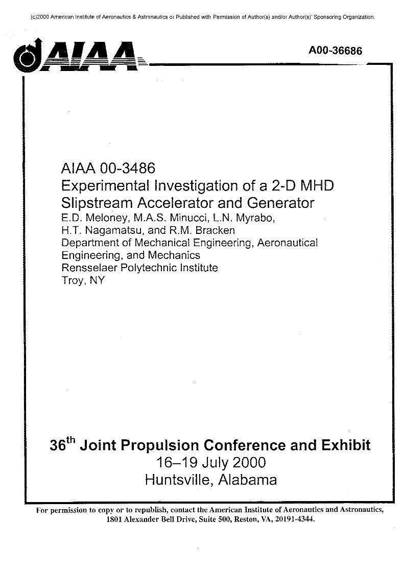
Tektronix VXI and Test Lab data acquisitionsystems record pressure data from PCB piezoelectrictransducers, shock tunnel heat transfer gauge signals,and the electric current and voltage readings from theelectrode power supply discharge. A computer codewritten for LabVIEW™ software serves as theinterface between researchers and the acquired dataand acquisition equipment. Fig. 3 is a schematicdrawing of the end of the Hypersonic Shock Tunneldriven section indicating the apparatus described.
A Beckman & Whitley Inc. model 350framing drum camera, on loan from the NASAMarshall Space Flight Center, has been modified toalso serve as a high-speed open-shutter drum camera.A recently acquired Oxford Lasers 'n-ShotController' is used to accurately time the pulses fromthe laser, which allows the camera to be properlyused in an open-shutter mode. This new piece ofequipment also adds a great deal of flexibility to thetiming and triggering setup of the shock tunnel. Inthis mode, the camera can be operated in conjunctionwith the timed pulses of the copper vapor laser to
provide a series of 35mm schlieren photographsduring the test time. By scanning and assembling thephotos, schlieren movies can then be produced whichgreatly enhance the value of the visual data. Inaddition, simple digital enhancements can be made tohelp further clarify the shock waves.
EXPERIMENTAL APPARATUS
The electrode power supply is connected tothe shock tunnel test section via a copper coaxialpower line (Fig. 2). An in-house designed and builtceramic feed-through plate enables the power line topass, isolated, through the test section steel wallbefore connecting to the model (Fig. 4). During theaxisymmetric MHD model tests, the coaxial line wasconnected to the two Bitter coils, while for the 2-Dflow accelerator wedge model tests, it is connected tothe two copper electrodes.
InstrumentationFeed Throug
CoaxialFeedThrough
Fig. 3 Layout of the Shock Tunnel and Instrumentation
Fig. 4 Test Section Power Feed Through Fig. 5 Permanent Magnet Assembly
American Institute of Aeronautics and Astronautics

(c)2000 American Institute of Aeronautics & Astronautics or Published with Permission of Author(s) and/or Author(s)1 Sponsoring Organization.
The wedge model was conceived with theidea of using the Maxwell Capacitor Bank to providethe electrode energy. It is for this reason thatpermanent magnets were chosen to simplify themodel and free the capacitor bank. Each one of theneodymium-iron-boron magnets measures 2.0-in. X1.5-in. X 0.5-in.; they are commercially availablefrom Edmund Scientific. Two such magnets wereglued together to create the bottom of the MHDchannel, which measures 2-in. wide by 3-in. long.They were then mounted on a cold rolled steel backplate 0.25 in. thick and epoxied into a pocketmachined in the wedge top surface, between the twoelectrodes. Figure 5 shows the two-magnet assemblyprior to its installation into the wedge model.
Fig. 6a Magnetic Field Strength over MHDChannel Area at z=0mm
MHD Magnetic FUU Map (z»«.33imnj
Fig. 6b Magnetic Field Strength over MHDChannel Area at z=6.35mm
A survey of the magnetic field has beencompleted and the field characteristics are asexpected. The field is strongest at the surface andweakens with distance. At its greatest intensity nearthe surface of the wedge model, the magnetic field is0.3 Tesla, and at all levels, the field strength remainsroughly constant over most of the surface of theMHD channel but drops off sharply near theelectrodes. Figures 6a and 6b are contours of themagnetic field strength over the MHD channel area attwo heights above the wedge model surface.
Since no power is required to drive thesemagnets during flow deceleration and accelerationinvestigations, the existing capacitor bank wasavailable to power the two solid copper electrodes.However, the discharge characteristics of thecapacitor bank were determined to be too intense forthe experiment at hand. Instead, a 1080 V, lowcurrent, low noise power supply was assembled usingeight 540 V Eveready type 497 batteries connected tothe coaxial power line. Because the 2-D modelconsists of a 10-in. wide wedge with a 40-degreeflow deflection angle, the Mach 7.6 oblique shockwave produces a higher degree of ionization thandoes the oblique shock for the axisymmetric modelcase. In addition, because the model is symmetricwith respect to the nozzle exit horizontal plane andthe permanent magnet and two electrodes areinstalled only in the upper surface (Fig. 8), it ispossible to observe both the MHD disturbed (top)and undisturbed (bottom) wedge flows in eachexperiment.
The Eveready battery power supply waschosen because of its high voltage ability andexpected high currents during the transient. Thecurrent, however, has not been high enough inprevious experiments. A lower voltage, high currentbattery supply has thus been envisioned with anexploding wire to start the MHD current flow. An in-house designed and built timing circuit controls theclosing and opening of the switch in Figure 7, thepresent power supply.
iHHHW
Tank
CoixUl Rjwer Lme
Hidt Cmrent Power
Fig. 7 Schematic of Electrode Power Supply and Delivery System
American Institute of Aeronautics and Astronautics
(c)2000 American Institute of Aeronautics & Astronautics or Published with Permission of Author(s) and/or Author(s)' Sponsoring Organization.
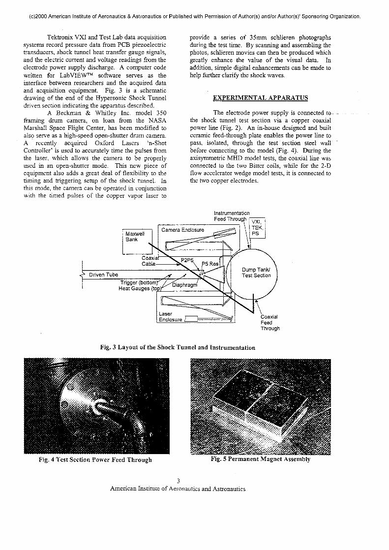
The MHD slipstream decelerator andaccelerator wedge model is shown in Fig. 8. Thecenterline of the exit region of the MHD wedgemodel is instrumented with two surface pressure tapsand two impact pressure probes, as diagrammed. Thetwo impact pressure probes can be adjusted verticallyto help determine the dynamic pressure distributiondownstream of the MHD channel centerline. Theimpact pressure probes are mounted symmetricallywith respect to the nozzle exit horizontal plane so thatboth dynamic pressures, downstream of the MHDchannel (top wedge surface) and downstream of theunaffected oblique shock wave (bottom surface), canbe measured simultaneously. In addition, an impactpressure rake has been recently machined to providefour pressure traces at varying heights above thewedge surface in place of either the top impact orbottom impact probe. Initial tests with this setuphave provided some interesting results. A thirdimpact pressure probe, located outside the model,measures the free stream pitot pressure necessary todetermine the nozzle exit flow conditions. Thewedge material is Delrin™, and due to its relativesoftness, the model was fitted with a removableDelrin™ leading edge, to allow the edge to bereplaced after excessive erosion. After more thanseventy runs, however, erosion of the original leadingedge is still not apparent.
Fig. 8 MHD Slipstream Accelerator Wedge Model
As in the axisymmetric inlet model, PCBmodel 112A22 piezoelectric pressure transducerswere used in all model probes and surface pressuretaps. Because of induced noise considerations and thedesire to minimize the grounding paths for thedischarge, fiber optic transducers are envisioned forthe project's next stage. A hollow stainless steelshaft connects the model to the test section main stingsupport system and carries the pressure transducer
cables to a vacuum feed-through plate. A pair ofionization gauges has also been constructed to helpdetermine flow conductivity. The first of these is asurface mount gauge, which provides a feedbacksignal whenever current from an external sourceflows across a 1mm gap between copper conductors.The second operates on the same principle but ispresently mounted off the bottom surface of themodel. When exploding wire tests commence theoff-surface gauge will be moved to the area behindthe MHD channel. . . . . . . .
The rectangular MHD electrodes are 0.75-in. X 3-in., 2-in. apart, and are removable to allowdifferent electrode shapes and concepts to be tested.To minimize flow disturbances, the electrodes havesharp leading edges and the ramp surfaces face thechannel's outside. Two small, 1mm diameter holesnear the electrode leading edges allow the use of acopper fuse wire to start the discharge during theflow acceleration attempts. Solid threaded copperrods, under the wedge top surface, connect theelectrodes to the cables that bring power from thehigh current power supply.
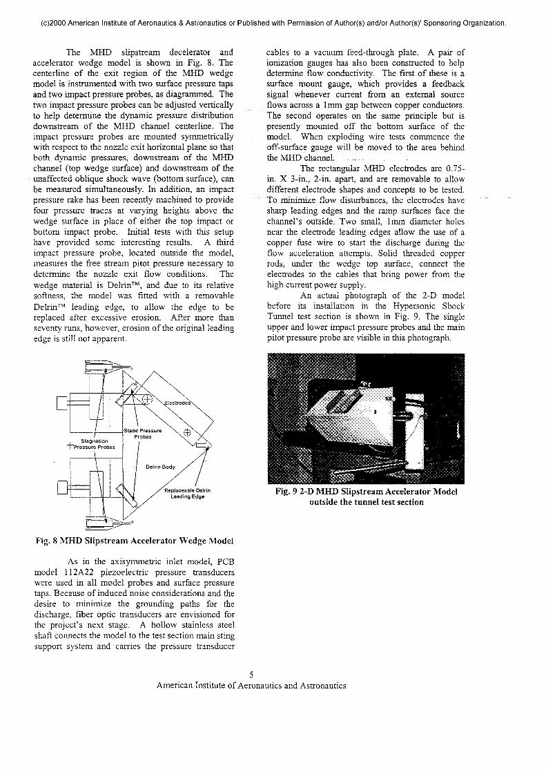
An actual photograph of the 2-D modelbefore its installation in the Hypersonic ShockTunnel test section is shown in Fig. 9. The singleupper and lower impact pressure probes and the mainpitot pressure probe are visible in this photograph.
Fig. 9 2-D MHD Slipstream Accelerator Modeloutside the tunnel test section
American Institute of Aeronautics and Astronautics

(c)2000 American Institute of Aeronautics & Astronautics or Published with Permission of Author(s) and/or Author(s)' Sponsoring Organization.
Fig. 10 2-D MHD Slipstream Accelerator Modelinstalled in the Shock Tunnel Test Section
Figure 10 shows the model installed in theRPI facility test section. The coaxial power line thatis used to deliver the high current pulse to the copperelectrodes can also be seen in this figure.
AIR PLASMA CHARACTERISTICS
An iterative solver has been developed inFORTRAN by previous graduate students(Mmucci,12 1991, Messitt,16 1999) to determine boththe reservoir and freestream conditions from initialdata for each run in the RPI facility. As mentionedpreviously, the RPI HST has been operated toproduce 4100 K stagnation temperature and 780 psiastagnation pressure in the reservoir section for thepresent investigation. These reservoir conditions aresufficient to produce between 6 ms and 8 ms of Mach7.6 flow in the test section. After expanding througha conical diverging nozzle, the flow statictemperature and static pressure are 450 K (810 R)and 0.020 psia, respectively.
Theoretical Flow Conditions
Using NACA 113517 (1953) and variousother resources, real gas conditions in the MHDchannel have been determined as accurately aspossible with current real gas theories and withoutintroducing unnecessary complexity. Boundarylayers are ignored in all calculations. The conditionson the wedge and behind the oblique shock wave are:
stagnation pressure = 7.9 psiastatic pressure = 0.88 psiastatic temperature = 2992 Kdensity = 7.369 x 10~3 kg/m3
Mach number = 2.3velocity = 2082 m/smass flow rate = 0.01580 kg/sflow power = 79.6 kWmass in channel = 0.58 mg
These calculations are based on freestreamconditions as follows:
stagnation pressure = 780 psiastatic pressure = 0.020 psiastagnation temperature = 4100 Kstatic temperature = 450 Kdensity =.0011 kg/m3
Mach number = 7.6
Of course, this implies that the MHD channelstagnation temperature is 4100 K.
Measured Flow Conditions
The flow conditions that have beenmeasured differ, sometimes significantly, fromtheory. In most cases, the impact pressure and staticpressure differ from the top to the bottom side of thewedge. In addition, the impact pressure issignificantly lower than theory would have it in allcases. The experimental data suggests the followingvalues:
channel-side stagnation pressure = 3.3 psiaopposing-side stagnation pressure = 4.5 psiachannel-side static pressure = 0.77 psiaopposing-side' static pressure =1.2 psia
Explanations offered for the difference inpressures measured from one side to the other includea misalignment of the model and magnetic fieldinterference with the transducers.
Gas Composition
The Chemical Equilibrium withApplications (CEA) computer code (Gordon &McBride,18 1994) was used to determine gascomposition at the conditions behind the obliqueshock wave. For the given conditions, the majorconstituents of the hot test gas, in order of decreasingabundance, are N2, O2, O, NO, Ar, CO2, CO, andother, less abundant particles, including freeelectrons.
Plasma Conductivity
The electrical properties of the wedge modelin the flow have also been determined bothexperimentally and theoretically. The most importantof these parameters, conductivity, has beendetermined entirely experimentally, because we havegood reason to believe that the gas is in a state ofchemical nonequilibrium, making it very difficult tocalculate.
American Institute of Aeronautics and Astronautics
(c)2000 American Institute of Aeronautics & Astronautics or Published with Permission of Author(s) and/or Author(s)1 Sponsoring Organization.
The conductivity has been determinedduring a series of runs with the wedge acting as aMHD generator. During these runs an external loadwas changed, which in turn changed the amount ofcurrent generated by the wedge. The plasmaresistance changed nonlinearly with this change.When run with the highest external load, theconductivity was determined to be 5.19 x 1CT5
mho/cm, while at the lowest external load, theconductivity was 3.50 x 10"3 mho/cm.
The open circuit voltage, V0, can bedetermined experimentally as the measuredelectromotive force that is induced with the highestexternal load. The experimentally determined opencircuit voltage for the MHD wedge generator modelin a Mach 7.6, 4100 K stagnation temperature, 780psia stagnation pressure flow is 10.6 volts with anexternal load of 762.2 k£l
Theoretically, this open circuit voltage canbe determined with the following relation (Blake,19
1999):
~ 108 (1)
where tA is the plasma velocity in cm/sec, B is themagnetic field strength in gauss, and L is theelectrode separation distance in cm. The theoreticalvalue of open circuit voltage thusly determined is32.2 volts.
Although the difference between thetheoretical and experimental values of this voltage issignificant, the order of magnitude is the same. Thetheoretical model does not account for boundarylayers over either the wedge or its electrodes,electrode sheaths (Schneider20, 1999), or the variationin the magnetic field strength with perpendiculardistance from the surface. Considering theseadditional physical phenomena, all of which decreasethe induced voltage, the theoretical open circuitvoltage agrees fairly well with the observed opencircuit voltage.
Conductivity was determinedexperimentally using the same method as Blake19
(1999). The plasma resistance, Rp, without anyexternal load, can be found from the followingequation:
(2)
where V is the measured potential between theelectrodes, and the induced current, /, is found usingOhm's Law:
(3)
where R^ is the external load. The conductivity, a, ofthe plasma in a channel with electrode area A andseparation distance L can then be determined by
<J = •AR.
(4)
Using a more conservative model fortheoretical open circuit voltage, the voltage drop atthe electrode sheaths can be estimated. As themagnetic field drops off uniformly with distance, theaverage field strength at a height of 9.53mm abovethe surface of the wedge (approximately half theelectrode height) will be used for the value of B.This value is 0.127 T. The result is a new theoreticalopen circuit voltage of 14.3 volts. The averageextracted voltage for the three runs with highestexternal load was 10.6 volts.
Equation 5 is a form of eq. 2, modified toinclude the contribution of the electrode sheaths.
(5)
Where V is the average measured voltage givenabove, V0 is the theoretical open circuit voltage, andVe is the combined voltage drop at the electrodesheaths. Using this method, the voltage drop at theelectrode sheaths is determined to be approximately3.7 volts.
ADDITIONAL GENERATOR RESULTS
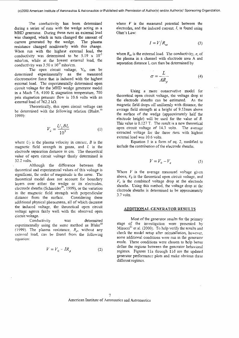
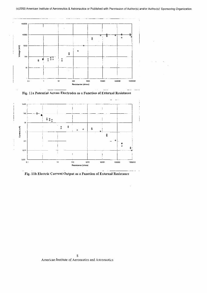
Most of the generator results for the primarystage of the investigation were presented byMinucci21 et al. (2000). To help verify the results andcheck the model setup after reinstallation, however,some additional conditions were run in the generatormode. These conditions were chosen to help betterdefine the regions between the generator behavioralregimes. Figures lla through lid are the updatedgenerator performance plots and make obvious thesedifferent regimes.
American Institute of Aeronautics and Astronautics
(c)2000 American Institute of Aeronautics & Astronautics or Published with Permission of Author(s) and/or Author(s)1 Sponsoring Organization.
10000
y iooog.
"o> 100
10
8 * ^ o oQ
§
o
*
_
V Q
0 <
10 100 1000
Resistance (ohms)10000 100000 1000000
Fig. lla Potential Across Electrodes as a Function of External Resistance
100 1000
Resistance (ohms)10000 100000 1000000
Fig. lib Electric Current Output as a Function of External Resistance
American Institute of Aeronautics and Astronautics

(c)2000 American Institute of Aeronautics & Astronautics or Published with Permission of Author(s) and/or Author(s)' Sponsoring Organization.
10000
EO ^nnn
^ .Ao v
> o^ o^ 0
oo
ooo
o °0«« * 4?« o
sii
!
0.001 0.01 0.1 1 10 100 1000
Current (mA)
Fig. lie Potential across Electrodes as a Function of Electric Current Output
oo
/oO o
o
Current (mA)
Fig. lid Power Output as a Function of Electric Current Output
The six additional conditions tested all seem to fit inwell with the past data, thereby greatly increasingconfidence in the accuracy of the data.
The greatest power extracted from thegenerator at any time was 12.5 mW. Given a flowpower of 79.6 kW, this implies an extractionefficiency of 1.6 x 10~5 %. This low extractionefficiency can again be attributed to low conductivityand high impedance at the electrode sheaths.
EXPLODING WIRE CONCEPT
At 3000 K static temperature the equilibriumconductivity of air is negligible. The experimentally
determined conductivity is nonzero primarily due tonitrogen species frozen in their reservoir state. Manymethods, therefore, have been envisioned toartificially increase the flow conductivity. Thesemethods include seeding, exploding trigger wires,high voltage discharges, and laser- or microwave-induced breakdown. For the next phase of the MHDwedge accelerator investigation, exploding triggerwires are to be used to drastically increaseconductivity and to create a "T-layer" or "paddle," asdescribed by Myrabo9 et a/. (1995), to essentiallypush the air through the MHD channel.
Although the MHD accelerator design callsfor a laser- or microwave-induced line breakdown,the trigger wire is a good simulator of this event. The
American Institute of Aeronautics and Astronautics
(c)2000 American Institute of Aeronautics & Astronautics or Published with Permission of Author(s) and/or Author(s)' Sponsoring Organization.
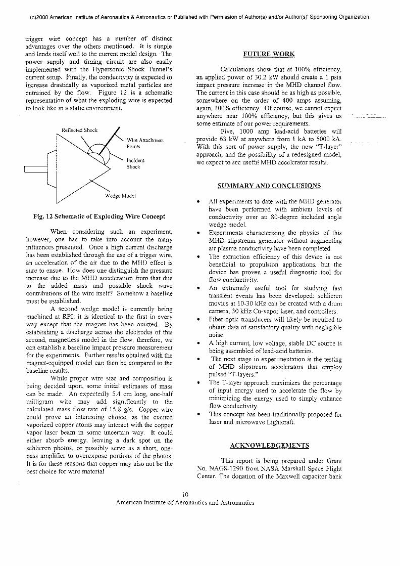
trigger wire concept has a number of distinctadvantages over the others mentioned. It is simpleand lends itself well to the current model design. Thepower supply and timing circuit are also easilyimplemented with the Hypersonic Shock Tunnel'scurrent setup. Finally, the conductivity is expected toincrease drastically as vaporized metal particles areentrained by the flow. Figure 12 is a schematicrepresentation of what the exploding wire is expectedto look like in a static environment.
Reflected Shock
Wire AttachmentPoints
IncidentShock
Wedge Model
Fig. 12 Schematic of Exploding Wire Concept
When considering such an experiment,however, one has to take into account the manyinfluences presented. Once a high current dischargehas been established through the use of a trigger wire,an acceleration of the air due to the MHD effect issure to ensue. How does one distinguish the pressureincrease due to the MHD acceleration from that dueto the added mass and possible shock wavecontributions of the wire itself? Somehow a baselinemust be established.
A second wedge model is currently beingmachined at RPI; it is identical to the first in everyway except that the magnet has been omitted. Byestablishing a discharge across the electrodes of thissecond, magnetless model in the flow, therefore, wecan establish a baseline impact pressure measurementfor the experiments. Further results obtained with themagnet-equipped model can then be compared to thebaseline results.
While proper wire size and composition isbeing decided upon, some initial estimates of masscan be made. An expectedly 5.4 cm long, one-halfmilligram wire may add significantly to thecalculated mass flow rate of 15.8 g/s. Copper wirecould prove an interesting choice, as the excitedvaporized copper atoms may interact with the coppervapor laser beam in some uncertain way. It couldeither absorb energy, leaving a dark spot on theschlieren photos, or possibly serve as a short, one-pass amplifier to overexpose portions of the photos.It is for these reasons that copper may also not be thebest choice for wire material
FUTURE WORK
Calculations show that at 100% efficiency,an applied power of 30.2 kW should create a 1 psiaimpact pressure increase in the MHD channel flow.The current in this case should be as high as possible,somewhere on the order of 400 amps assuming,again, 100% efficiency. Of course, we cannot expectanywhere near 100% efficiency, but this gives ussome estimate of our power requirements.
Five, 1000 amp lead-acid batteries willprovide 63 kW at anywhere from 1 kA to 5000 kA.With this sort of power supply, the new "T-layer"approach, and the possibility of a redesigned model,we expect to see useful MHD accelerator results.
SUMMARY AND CONCLUSIONS
All experiments to date with the MHD generatorhave been performed with ambient levels ofconductivity over an 80-degree included anglewedge model.Experiments characterizing the physics of thisMHD slipstream generator without augmentingair plasma conductivity have been completed.The extraction efficiency of this device is notbeneficial to propulsion applications, but thedevice has proven a useful diagnostic tool forflow conductivity.An extremely useful tool for studying fasttransient events has been developed: schlierenmovies at 10-30 kHz can be created with a drumcamera, 30 kHz Cu-vapor laser, and controllers.Fiber optic transducers will likely be required toobtain data of satisfactory quality with negligiblenoise.A high current, low voltage, stable DC source isbeing assembled of lead-acid batteries.The next stage in experimentation is the testing
of MHD slipstream accelerators that employpulsed "T-layers."The T-layer approach maximizes the percentageof input energy used to accelerate the flow byminimizing the energy used to simply enhanceflow conductivity.This concept has been traditionally proposed forlaser and microwave Lightcraft.
ACKNOWLEDGEMENTS
This report is being prepared under GrantNo. NAGS-1290 from NASA Marshall Space FlightCenter. The donation of the Maxwell capacitor bank
10American Institute of Aeronautics and Astronautics

(c)2000 American Institute of Aeronautics & Astronautics or Published with Permission of Author(s) and/or Author(s)' Sponsoring Organization.
and the accompanying control cabinet by the USArmy Picatiny Arsenal is gratefully acknowledged.Also, the second author would like to acknowledgethe support for his Post-doctoral Program at theRensselaer Polytechnic Institute from the BrazilianAir Force. Finally, the authors would like toacknowledge the important contributions to thisproject from K. Shanahan, R. Nolan, A. Zielinski,J.M. Kerl, A.D. Panetta, D.G. Messitt, and C.Vannier.
REFERENCES
1. Rosa, R.J., "Magnetohydrodynamic Generatorsand Nuclear Propulsion," ARS Journal,August, 1962,pp.l221-1230.
2. Nagamatsu, H.T., and Sheer, R.E.Jr.,"Magnetohydrodynamics Results for HighlyDissociated and Ionized Air Plasma," ThePhysics of Fluids, Vol. 9, September 1961,pp. 1073-1084.
3. Nagamatsu, H.T., Sheer, R.E. Jr., and Well, J.A.,"Non-Linear Electrical Conductivity ofPlasma for Magnetohydrodynamic PowerGeneration," ARS Paper 2632-62,November 1962.
4. Way, S., DeCorso, S.M., Hundstud, R.L., Kenney,G.A., Stewart, W., and Young, W.E.,"Experiments with MHD PowerGeneration," Trans. Am. Soc. Mech. Eng., J.Eng. Power 83, Series A. October 1961,pp.394-408.
5. Steg, L. and Sutton, G.W., "The Prospects ofMHD Power Generation," Astronautics 5,August 1960, pp.22-25.
6. Ericson, W.B., Maciulaitis, A., Spagnolo, F.A.,Loefler, A.L. Jr., Scheuing, R.A., andHopkins, H.B. Jr., "An Investigation ofMHD Flight Control," Grumman AircraftEngineering Corp., National ElectronicsConference, Dayton, Ohio, May, 14-16,1962.
7. Covault, G. " 'Global Presence' Objective DrivesHypersonic Research," Aviation Week &Space Technology, April 5, 1999, pp. 54-58.
8. Gurijanov, E.P., Harsha, P.T. " AJAX: NewDirections in Hypersonic Technology,"A1AA Paper 96-4609, 1996.
9. Myrabo, L.N., Mead, D.R, Raizer, Y.P.,Surzhikov, and Rosa, R.J., "HypersonicMHD Propulsion System Integration for aManned Laser-Boosted TransatmosphericAerospacecraft," AIAA Paper, June 1995.
10. Kerl, J.M., Myrabo, L.N., Nagamatsu, H.T.,Minucci, M.A.S., and Meloney, E.D.,"MHD Slipstream Accelerator Investigationin the RPI Hypersonic Shock Tunnel, "
- ' . "7. AIAA Paper 99-2842, July 1999.
11. Kerl, J.M., Myrabo, L.N., Nagamatsu, H.T.,Minucci, M.A.S., and _ Meloney, E.D.,"MHD Slipstream Accelerator Investigationin the RPI Hypersonic Shock Tunnel,"Rensselaer Polytechnic Report for NASAMarshall Space Flight Center, Grant No.NAG8-1290, July 15, 1999.
12. Minucci, M.A.S., "An Experimental Investigationof a 2-D Scramjet Inlet at Flow MachNumbers of 8 to 25 and StagnationTemperatures of 800 to 4.100 K, " Ph. D.Thesis Dissertation, Department ofMechanical Engineering, AeronauticalEngineering & Mechanics, RensselaerPolytechnic Institute, Troy, New York,USA. May 1991.
13. Minucci, M.A.S., Nagamatsu, H.T., "HypersonicShock-Tunnel Testing at an EquilibriumInterface Condition of 4100 K," Journal ofThermophysics and Heat Transfer, Vol. 7,No. 2, 1994, pp. 251-260.
14. Nascimento, M.A.C., "Gaseous Piston Effect inShock Tube/Tunnel When Operating rn theEquilibrium Interface Condition," Ph.D.Thesis Dissertation, Instituto Tecnologico deAeronautica - ITA, Sao Jose dos c-ampos,Sao Paulo, Brazil, October 1998.
15. Nascimento, M.A.C., Minucci, M.A.S., Ramos,A.G., and Nagamatsu, H.T., "Numerical andExperimental Studies on the HypersonicGaseous Piston Shock Tunnel," Proceedingsof the 21" International Symposium onShock Waves, September 1997.
16. Messitt, D.G., "Computational and ExperimentalInvestigation of 2-D Scramjet Inlets andHypersonic Flow over a Sharp Flat Plate,"Ph. D. Thesis Dissertation, Department ofMechanical Engineering, AeronauticalEngineering & Mechanics, Rensselaer
11American Institute of Aeronautics and Astronautics

(c)2000 American Institute of Aeronautics & Astronautics or Published with Permission of Author(s) and/or Author(s)' Sponsoring Organization.
Polytechnic Institute, Troy, New York. May1999.
17. Ames Research Staff, "Equations, Tables, andCharts for Compressible Flow," NACAReport 1135, 1953.
18. Gordon, S. and McBride, B., "Computer Programfor Calculation of Complex ChemicalEquilibrium Compositions andApplications," NASA RP-1311, 1994.
19. Blake, S., "Magnetohydrodynamic Results forHighly Dissociated and Ionized Air Plasmafor~Mach 30 and 11,600 K," M.S. ThesisDissertation, Rensselaer PolytechnicInstitute, August 1999.
20. Schneider, M.N., Macheret, S.O., and Miles,R.B., "Electrode Sheaths and BoundaryLayers in Hypersonic MHD Channels,"AIAA Paper 99-3532, July, 1999.
21. Minucci, M.A.S., Meloney, E.D., Nagamatsu,H.T., Myrabo, L.N., and Bracken, R.M.,"Experimental Investigation of a 2-D MHDSlipstream Generator and Accelerator withM.O = 7.6 and T0= 4100 K," AIAA Paper GO-0446, January 2000.
12American Institute of Aeronautics and Astronautics