Embed Size (px)
Citation preview
13th World Conference on Earthquake Engineering Vancouver, B.C., Canada
August 1-6, 2004 Paper No. 2919
EXPERIMENTAL INVESTIGATION AND DYNAMIC SIMULATIONS OF
LOW-RISE STEEL BUILDINGS FOR EFFICIENT SEISMIC DESIGN
Patrick PAULTRE1, Jean PROULX2, Carlos E. VENTURA3, Robert TREMBLAY4, Colin A. ROGERS5, Charles-Philippe LAMARCHE6, Martin TUREK7
SUMMARY This paper presents an overview of an ongoing research project that was initiated to better understand the dynamic behaviour of low-rise steel buildings that rely on metal roof deck diaphragm response for lateral seismic resistance. The project includes a large ambient and forced vibration test program on actual building structures located both in eastern and western regions of Canada. Test results include natural frequencies, mode shapes, and damping ratios. For several buildings, tests are conducted at various stages during the construction so that the contribution of the different building components to the dynamic properties of the structures can be assessed. Laboratory testing is also conducted to determine shear stiffness properties of roof diaphragm assemblies, including the contribution of non-structural roofing material. Test results are used to develop numerical modelling techniques capable of reproducing field test data for the buildings studied. This project should permit the use of advanced analytical tools for cost-efficient seismic of low-rise steel buildings.
INTRODUCTION Single-storey steel buildings are used for light industrial, commercial, and recreational purposes and represent a vast proportion of the building stock in Canada. Most of these buildings are located in regions of active and moderate seismicity levels on the Pacific coast and along the St-Lawrence and Ottawa
1 Professor, Dept. of Civil Eng., Sherbrooke University, Canada; [email protected] 2 Professor, Dept. of Civil Eng., Sherbrooke University, Canada; [email protected] 3 Professor, Dept. of Civil Eng., University of British Columbia, Canada ; [email protected] 4 Professor, Dept. of Civil, Geological & Mining Eng., Ecole Polytechnique of Montreal, Canada;
[email protected] 5 Assistant Professor, Dept. of Civil Eng. & Applied Mechanics, McGill University, Canada;
[email protected] 6 M.Sc. Candidate, Dept. of Civil Eng., Sherbrooke University, Canada;
[email protected] 7 Ph.D. Candidate, Dept. of Civil Eng., University of British Columbia, Canada; [email protected]
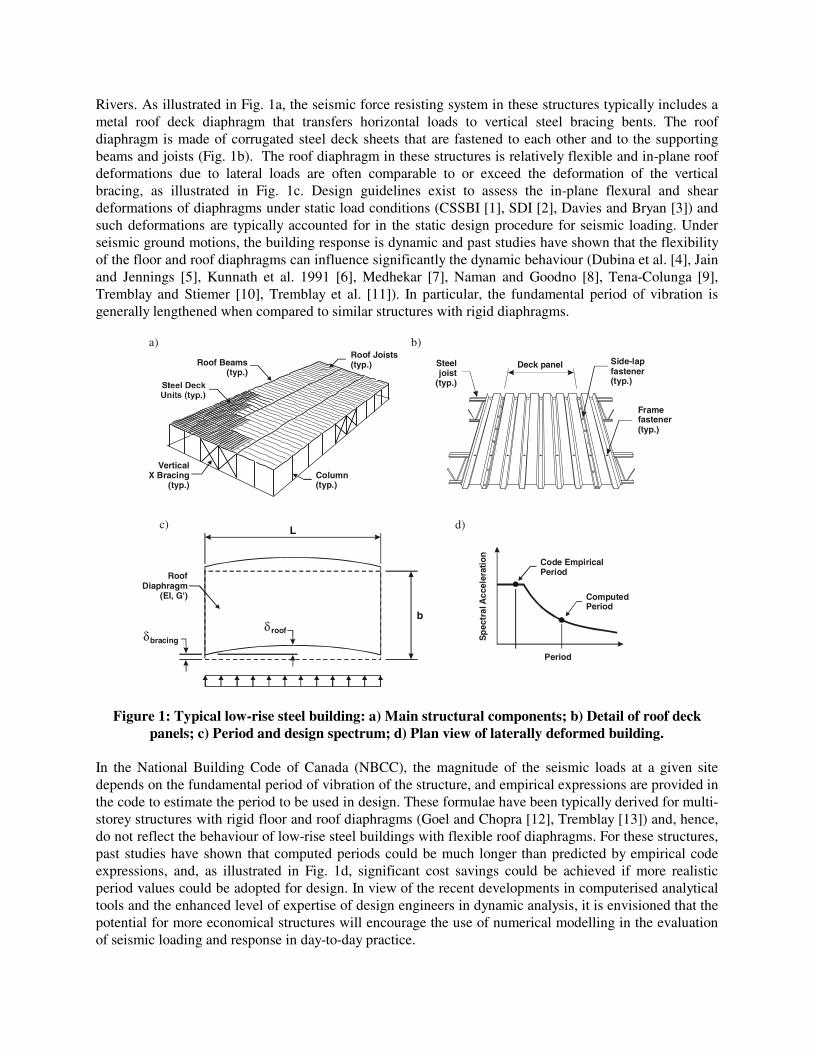
Rivers. As illustrated in Fig. 1a, the seismic force resisting system in these structures typically includes a metal roof deck diaphragm that transfers horizontal loads to vertical steel bracing bents. The roof diaphragm is made of corrugated steel deck sheets that are fastened to each other and to the supporting beams and joists (Fig. 1b). The roof diaphragm in these structures is relatively flexible and in-plane roof deformations due to lateral loads are often comparable to or exceed the deformation of the vertical bracing, as illustrated in Fig. 1c. Design guidelines exist to assess the in-plane flexural and shear deformations of diaphragms under static load conditions (CSSBI [1], SDI [2], Davies and Bryan [3]) and such deformations are typically accounted for in the static design procedure for seismic loading. Under seismic ground motions, the building response is dynamic and past studies have shown that the flexibility of the floor and roof diaphragms can influence significantly the dynamic behaviour (Dubina et al. [4], Jain and Jennings [5], Kunnath et al. 1991 [6], Medhekar [7], Naman and Goodno [8], Tena-Colunga [9], Tremblay and Stiemer [10], Tremblay et al. [11]). In particular, the fundamental period of vibration is generally lengthened when compared to similar structures with rigid diaphragms.
Roof Joists(typ.) Roof Beams
(typ.)
Column(typ.)
VerticalX Bracing
(typ.)
Period
bracingroofδ
δ
ComputedPeriod
Code EmpiricalPeriod
Sp
ectr
al A
ccel
erat
ion
L
b
a) b)
c) d)
Deck panel
Framefastener(typ.)
Steeljoist
(typ.)
Side-lapfastener(typ.)
RoofDiaphragm
(EI, G')
Figure 1: Typical low-rise steel building: a) Main structural components; b) Detail of roof deck panels; c) Period and design spectrum; d) Plan view of laterally deformed building.
In the National Building Code of Canada (NBCC), the magnitude of the seismic loads at a given site depends on the fundamental period of vibration of the structure, and empirical expressions are provided in the code to estimate the period to be used in design. These formulae have been typically derived for multi-storey structures with rigid floor and roof diaphragms (Goel and Chopra [12], Tremblay [13]) and, hence, do not reflect the behaviour of low-rise steel buildings with flexible roof diaphragms. For these structures, past studies have shown that computed periods could be much longer than predicted by empirical code expressions, and, as illustrated in Fig. 1d, significant cost savings could be achieved if more realistic period values could be adopted for design. In view of the recent developments in computerised analytical tools and the enhanced level of expertise of design engineers in dynamic analysis, it is envisioned that the potential for more economical structures will encourage the use of numerical modelling in the evaluation of seismic loading and response in day-to-day practice.

Very limited physical evidence has been made available to validate the findings of analytical studies. Shake table testing of a 1:7.5 scaled model of a simple rectangular bare steel building frame with a metal roof deck diaphragm (Tremblay and Bérair [14], Tremblay et al. [15]) gave excellent agreement between the measured response and the analytical simulations. The period of an actual building as obtained from field testing measurements by Ventura [16] was found, however, to be much shorter than predicted analytically by Medhekar [7]. Similar differences between in-situ measurements and analytical predictions were found by Bakhtavar [17] for a 6-storey steel building structure and by Goel and Chopra [12] for a number of instrumented steel frame buildings in California. This discrepancy is generally attributed to the contribution of non-structural components such as the exterior cladding or the interior wall partitions to the lateral stiffness of the structure. In view of their inherent flexibility and lightness and because they are built with relatively smaller structural elements, single-storey steel structures are probably more sensitive to the stiffening effects of architectural components. In addition, the flexibility of the structure originates for a large portion from roof diaphragm deformations. Medhekar [7] suggested that such deformability could be limited by the presence of the non-structural roofing material. Bakhtavar [17] also indicated that uncertainties also exist regarding other dynamic properties such as periods of vibration in higher modes or effective modal damping. Recognising the importance of low-rise metal building structures for the Canadian construction industry and the fact that the design of these structures in several large urban regions of Canada is governed by earthquake resistance provisions, a research program was recently initiated to expand the existing database and to develop numerical modelling techniques that would eventually allow the use of advanced dynamic analysis tools for the seismic design of low-rise steel buildings. This project involves researchers from four Canadian Universities (the University of Sherbrooke, Sherbrooke, QC, the University of British Columbia, Vancouver, BC, and École Polytechnique of Montreal and McGill University, Montreal, QC) and is carried out in collaboration with representatives of the steel industry. A major portion of the work is dedicated to in-situ ambient vibration testing to measure the periods of vibration and damping ratios of actual building structures located in both eastern and western Canada. Large scale laboratory testing is also carried out to better assess steel diaphragm flexibility properties, including the effects of non-structural components. This experimental work is complemented by analytical studies in which the results of in-situ and laboratory testing are combined and used to develop modelling techniques that permit the accurate reproduction of the dynamic behaviour of the buildings as obtained in the field testing. This paper provides an overview of the experimental activities that have been conducted in the project. Preliminary test results are also presented. The field testing techniques are described and preliminary results are presented and discussed. Laboratory experiments on roof diaphragms are also described and comments on the effects of non-structural components are provided. This part of the work is covered in more detail in a separate paper Tremblay et al. [18]. The report of activities is preceded by a presentation of a parametric study that was performed to assess the impact of roof flexibility on building periods in the context of application of recent code documents.
EXPECTED DYNAMIC BEHAVIOUR OF SINGLE STOREY STEEL BUILDINGS A parametric study was conducted to assess the influence of various parameters on the fundamental period of vibration of typical low-rise steel building structures designed according to recent building codes. The study also provided a comparison between the period used in design and the actual building period, as can be obtained from simple analytical methods. The scope was limited to uniform rectangular buildings with constant height. The seismic loads were determined in accordance with the provisions of the upcoming NBCC 2005 (Heidebrecht [19], NRCC [20]) and the CSA-S16-01 Standard [21] was used for the design of the steel structures. Different building areas (500, 1000, 2000, 3000, and 4000 m2), aspect ratios (0.50, 0.67, 1.0, 1.50, 2.00, and 2.50) and heights (4.5, 6.0, 7.5, 9.0, and 10.5 m) were considered. For all
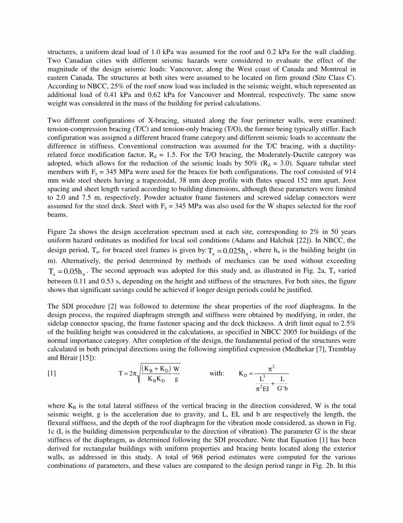
structures, a uniform dead load of 1.0 kPa was assumed for the roof and 0.2 kPa for the wall cladding. Two Canadian cities with different seismic hazards were considered to evaluate the effect of the magnitude of the design seismic loads: Vancouver, along the West coast of Canada and Montreal in eastern Canada. The structures at both sites were assumed to be located on firm ground (Site Class C). According to NBCC, 25% of the roof snow load was included in the seismic weight, which represented an additional load of 0.41 kPa and 0.62 kPa for Vancouver and Montreal, respectively. The same snow weight was considered in the mass of the building for period calculations. Two different configurations of X-bracing, situated along the four perimeter walls, were examined: tension-compression bracing (T/C) and tension-only bracing (T/O), the former being typically stiffer. Each configuration was assigned a different braced frame category and different seismic loads to accentuate the difference in stiffness. Conventional construction was assumed for the T/C bracing, with a ductility-related force modification factor, Rd = 1.5. For the T/O bracing, the Moderately-Ductile category was adopted, which allows for the reduction of the seismic loads by 50% (Rd = 3.0). Square tubular steel members with Fy = 345 MPa were used for the braces for both configurations. The roof consisted of 914 mm wide steel sheets having a trapezoidal, 38 mm deep profile with flutes spaced 152 mm apart. Joist spacing and sheet length varied according to building dimensions, although these parameters were limited to 2.0 and 7.5 m, respectively. Powder actuator frame fasteners and screwed sidelap connectors were assumed for the steel deck. Steel with Fy = 345 MPa was also used for the W shapes selected for the roof beams. Figure 2a shows the design acceleration spectrum used at each site, corresponding to 2% in 50 years uniform hazard ordinates as modified for local soil conditions (Adams and Halchuk [22]). In NBCC, the design period, Ta, for braced steel frames is given by:
na 0.025h T = , where hn is the building height (in
m). Alternatively, the period determined by methods of mechanics can be used without exceeding
na 0.05h T = . The second approach was adopted for this study and, as illustrated in Fig. 2a, Ta varied
between 0.11 and 0.53 s, depending on the height and stiffness of the structures. For both sites, the figure shows that significant savings could be achieved if longer design periods could be justified.
The SDI procedure [2] was followed to determine the shear properties of the roof diaphragms. In the design process, the required diaphragm strength and stiffness were obtained by modifying, in order, the sidelap connector spacing, the frame fastener spacing and the deck thickness. A drift limit equal to 2.5% of the building height was considered in the calculations, as specified in NBCC 2005 for buildings of the normal importance category. After completion of the design, the fundamental period of the structures were calculated in both principal directions using the following simplified expression (Medhekar [7], Tremblay and Bérair [15]):
[1] ( )
TK K
K K
W
gB D
B D
=+
2π with: KL
EI
L
G b
D =+
π
π
2
3
2 '
where KB is the total lateral stiffness of the vertical bracing in the direction considered, W is the total seismic weight, g is the acceleration due to gravity, and L, EI, and b are respectively the length, the flexural stiffness, and the depth of the roof diaphragm for the vibration mode considered, as shown in Fig. 1c (L is the building dimension perpendicular to the direction of vibration). The parameter G' is the shear stiffness of the diaphragm, as determined following the SDI procedure. Note that Equation [1] has been derived for rectangular buildings with uniform properties and bracing bents located along the exterior walls, as addressed in this study. A total of 968 period estimates were computed for the various combinations of parameters, and these values are compared to the design period range in Fig. 2b. In this
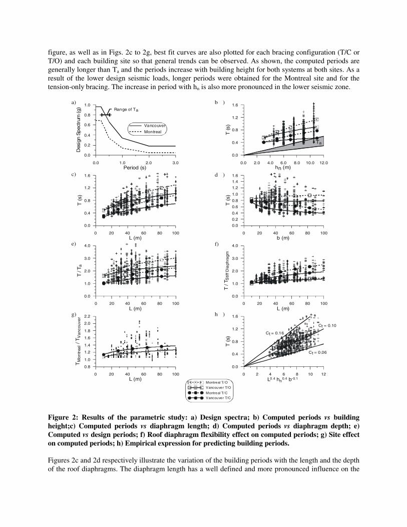
figure, as well as in Figs. 2c to 2g, best fit curves are also plotted for each bracing configuration (T/C or T/O) and each building site so that general trends can be observed. As shown, the computed periods are generally longer than Ta and the periods increase with building height for both systems at both sites. As a result of the lower design seismic loads, longer periods were obtained for the Montreal site and for the tension-only bracing. The increase in period with hn is also more pronounced in the lower seismic zone.
0.0 1.0 2.0 3.0Period (s)
0.0
0.2
0.4
0.6
0.8
1.0
Des
ign
Spe
ctru
m(g
)
Vancouver
Montreal
Range of Ta
a)
0.0 2.0 4.0 6.0 8.0 10.0 12.0hn (m)
0.0
0.4
0.8
1.2
1.6
T(s
)
Montreal T/O
Vancouve r T/O
Montreal T/C
Vancouve r T/C
b )
Ta
0 20 40 60 80 100L (m)
0.0
0.4
0.8
1.2
1.6
T(s
)
c)
0 20 40 60 80 100b (m)
0.0
0.2
0.4
0.6
0.8
1.0
1.2
1.4
1.6
T(s
)
d )
0 20 40 60 80 100L (m)
0.0
1.0
2.0
3.0
4.0
T/T
a
e)
0 20 40 60 80 100L (m)
0.0
1.0
2.0
3.0
4.0
T/T
Stif
fDia
phra
gm
f)
0 20 40 60 80 100L (m)
0.8
1.0
1.2
1.4
1.6
1.8
2.0
2.2
TM
on
trea
l/T
Va
nco
uve
r
0 2 4 6 8 10 12L0.4 hn
0.4 b-0.1
0.0
0.4
0.8
1.2
1.6
T(s
)
g) h )
Ct = 0.16
Ct = 0.10
Ct = 0.06
Figure 2: Results of the parametric study: a) Design spectra; b) Computed periods vs building height;c) Computed periods vs diaphragm length; d) Computed periods vs diaphragm depth; e) Computed vs design periods; f) Roof diaphragm flexibility effect on computed periods; g) Site effect on computed periods; h) Empirical expression for predicting building periods. Figures 2c and 2d respectively illustrate the variation of the building periods with the length and the depth of the roof diaphragms. The diaphragm length has a well defined and more pronounced influence on the
period, compared to its depth: for all systems and sites, the period elongates as the length of the diaphragm is increased. Such a response was expected because both the flexural and shear spans of the roof increase with the dimension L. On the contrary, the period of tension-compression braced frames reduces when the dimension of the diaphragm is increased in the direction parallel to the motion. In these structures, the bracing bents are typically much stiffer relative to the roof diaphragm and most of the lateral deformations take place in the roof. For a given building area, increasing the depth of the diaphragm reduces the bending and shear spans, as well as the shear stresses in the diaphragm. For tension-only bracing, the variation of the diaphragm depth has virtually no impact on the behaviour. Figures 2e and 2f confirm the significance of the roof diaphragm length and flexibility on the fundamental building period. In Figure 2e, the difference between the computed and design periods for each case is found to generally increase with the dimension L. In Figure 2f, the period of each structure was determined neglecting the flexural and shear flexibilities of the diaphragm and then compared to the period obtained with the actual diaphragm properties. As in the previous case, the difference increases with the length of the diaphragm. Figure 2g compares the computed fundamental periods of the same buildings located at the two sites. In this figure, the trend lines are presented only for the two bracing configurations. As indicated earlier, the use of lower seismic loads for Montreal led to more flexible structures and, thereby, longer fundamental periods. On average, the ratios between Montreal and Vancouver values are 1.3 and 1.2 for the T/C and T/O systems, respectively. Note that the seismic loads in Vancouver are, on average over the design period range, 1.6 times larger than in Montreal. As illustrated in Figure 2, the period difference between the two sites generally increases with the length of the diaphragm, indicating that roof flexibility effects can be more pronounced in lower seismic regions. The highest ratios between the two sites are observed, however, for intermediate building lengths, but examination of the data does not reveal any clear trend in terms of building aspect ratio for these values. This study showed that the main building geometrical parameters influencing the fundamental period of low-rise steel buildings are the length of the diaphragm perpendicular to the motion and the building height. The dimension of the diaphragm parallel to the motion has less pronounced effects. From
regression analysis of the results, an empirical expression of the form bh LC T zyn
xt = can be developed to estimate the period of single-storey steel buildings, the parameters Ct, x, y, and z being adjusted for the site (hazard magnitude) and the type of vertical bracing. For the whole data set considered herein, good correlation is obtained using Ct = 0.10, x = y = 0.4 and z = -0.10. As illustrated in Fig. 2h, significant scatter still exists, however, due to the variation caused by the level of seismic loads and the type of bracing configuration.
IN-SITU TEST PROGRAM Modelling the true behaviour of civil engineering structures remains the most difficult step in dynamic or seismic analysis. Simple analytical models (as discussed in the previous section) that are commonly used in practice, typically underestimate the stiffness of steel buildings because they only include the main framing elements. The contribution of secondary structural elements and non-structural components is generally omitted in analysis, as well as secondary effects such as partial connection fixity, finite member sizes, etc. This may result in unconservative period estimates (values that are too high), for seismic design. Other important parameters that need to be defined for seismic analysis are the mass distribution and the damping characteristics. A considerable amount of research has been carried out in the past decade on seismic analysis and modelling of various structures and it has been clearly demonstrated that satisfactory performance could only be achieved for these numerical techniques if they were calibrated using dependable full-scale test results. For structural dynamic properties, full-scale ambient and forced vibration tests provide reliable data for the evaluation of the influence of key parameters.
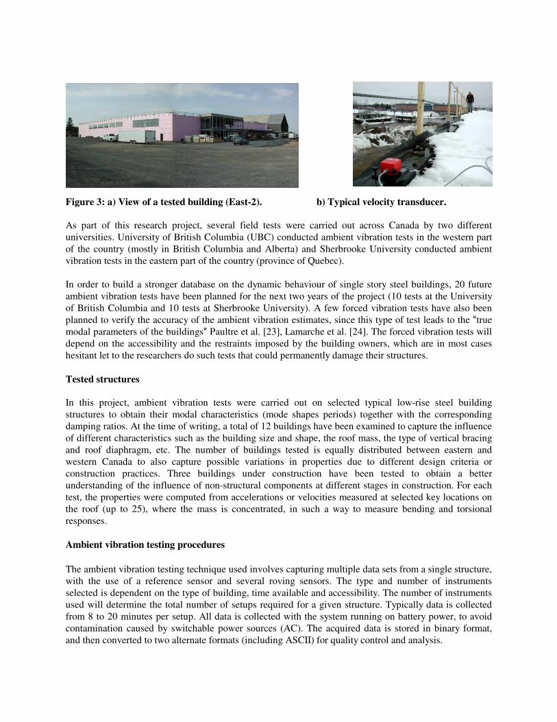
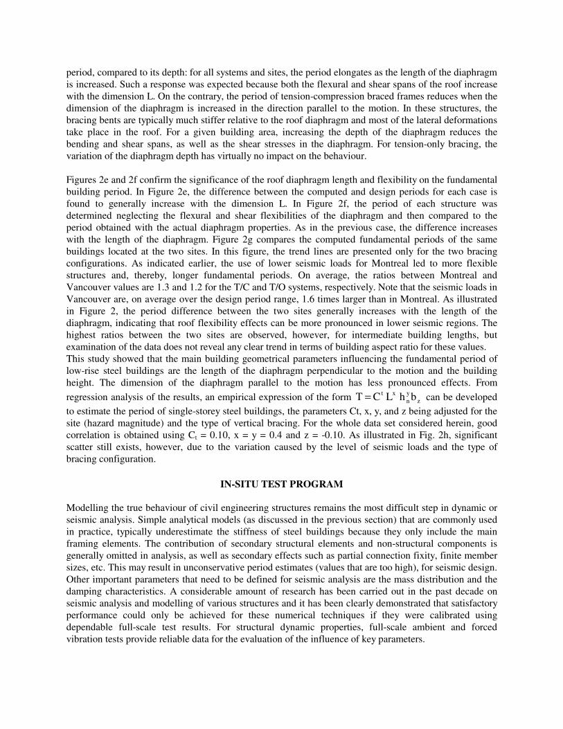
Figure 3: a) View of a tested building (East-2). b) Typical velocity transducer. As part of this research project, several field tests were carried out across Canada by two different universities. University of British Columbia (UBC) conducted ambient vibration tests in the western part of the country (mostly in British Columbia and Alberta) and Sherbrooke University conducted ambient vibration tests in the eastern part of the country (province of Quebec). In order to build a stronger database on the dynamic behaviour of single story steel buildings, 20 future ambient vibration tests have been planned for the next two years of the project (10 tests at the University of British Columbia and 10 tests at Sherbrooke University). A few forced vibration tests have also been planned to verify the accuracy of the ambient vibration estimates, since this type of test leads to the "true modal parameters of the buildings" Paultre et al. [23], Lamarche et al. [24]. The forced vibration tests will depend on the accessibility and the restraints imposed by the building owners, which are in most cases hesitant let to the researchers do such tests that could permanently damage their structures. Tested structures In this project, ambient vibration tests were carried out on selected typical low-rise steel building structures to obtain their modal characteristics (mode shapes periods) together with the corresponding damping ratios. At the time of writing, a total of 12 buildings have been examined to capture the influence of different characteristics such as the building size and shape, the roof mass, the type of vertical bracing and roof diaphragm, etc. The number of buildings tested is equally distributed between eastern and western Canada to also capture possible variations in properties due to different design criteria or construction practices. Three buildings under construction have been tested to obtain a better understanding of the influence of non-structural components at different stages in construction. For each test, the properties were computed from accelerations or velocities measured at selected key locations on the roof (up to 25), where the mass is concentrated, in such a way to measure bending and torsional responses. Ambient vibration testing procedures The ambient vibration testing technique used involves capturing multiple data sets from a single structure, with the use of a reference sensor and several roving sensors. The type and number of instruments selected is dependent on the type of building, time available and accessibility. The number of instruments used will determine the total number of setups required for a given structure. Typically data is collected from 8 to 20 minutes per setup. All data is collected with the system running on battery power, to avoid contamination caused by switchable power sources (AC). The acquired data is stored in binary format, and then converted to two alternate formats (including ASCII) for quality control and analysis.
A typical test setup for a single story steel structure is presented in Fig. 4a. This horizontal measurement pattern was the most commonly used for the symmetrical buildings (most buildings tested were symmetrical along both principal directions). On the perimeter of the buildings, accelerations (or velocities) were not measured in both orthogonal directions for all measurement locations to avoid collecting redundant information. Since the transducers are carefully placed on the principal and secondary beams (or girder) axis, it can be assumed that no axial deformations occur along these lines. This assumption was verified for each test by comparing the relative accelerations (or velocities) recorded in the corners of the building.
Figure 4: a) Plan view of a typical transducer configuration on a building b) & c) Plan view of a typical first and second in plane bending mode in the N-S direction.
The position the reference transducers is shown in Fig. 4 a. The transducers used as references had to be carefully placed in order to minimise the error introduced by the systematic scaling of the data sets collected during each setups. Since the scaling is performed in the frequency domain, the optimal position of the references can be estimated by analysing the predicted mode shapes associated to the structures. The data set are scaled comparing the relative amplitude of the reference transducers from one data set to another at every discrete frequency obtained from the Fourier Transform of the recorded signals. In order to avoid scaling high-amplitude components by a near zero value close to a resonant frequency, care must be taken to ensure that reference accelerometers are not placed in the vicinity of a nodal region (zero amplitude region). Figures 4b and 4c show typical first and second mode shapes in the N-S direction. It is clear from this figure that if the reference transducers are placed on the centerline of the building, the frequency components near the first mode will be properly scaled and frequency components near the second mode will suffer from significant numerical errors. To avoid this situation, the reference transducers are positioned between the maximum amplitude axis of the first and second mode in both direction.
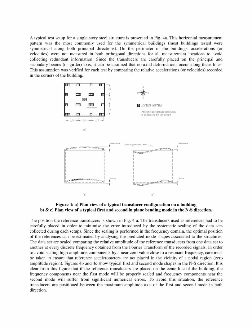
For each instrument configuration, several measurements of ambient vibration responses are recorded. The Frequency Domain Decomposition (FDD) algorithm is used to compute the modal parameters from the ambient data collected on the field. This technique has been evaluated successfully and it has been demonstrated in a controlled laboratory environment that valuable natural frequencies, mode shapes and modal damping estimate could be obtained using the FDD technique (Lamarche et al. [24]). Examples of the first two modes of vibration from two of the tested buildings are shown in Fig. 5. Each figure illustrates the shape of the mode with respect to the undeformed shape.
a) Mode 1
f = 3,0 Hz
Mode 2
f = 3.4 Hz
b)
Figure 5: Mode shapes and frequencies for the first bending modes in each direction: a) Building East-2; b) Building East-5.
Ambient vibration test results Table 1 presents the fundamental periods of vibrations in each of the two principal directions as obtained from the 12 field experiments. For Buildings East-2 and West-1, measurements were taken during the construction and after completion of the building. For Building West-1, two phases of construction were measured. In both phases all of the exterior walls were in place. In test one, only the roof joists were in place, and in test two the steel roof decking had been installed. All buildings are generally rectangular in plan except Buildings West-2 and West-5. Structure West-2 includes three sections that are staggered in plan while Building West-5 has exterior walls arranged at an angle in three of the building corners. Buildings East-3 and East-4 have identical dimensions and are located in the same city. For all structures except Buildings East-5 and West-2, Mode 1 corresponds to vibrations perpendicular to the long dimension of the buildings, i.e. involves in-plane flexure of the diaphragm over the longest span. For Building East-5, the shape of Mode 2 suggests that the response in that mode was partially restrained, as shown in Fig. 5b, and may not be representative of the behaviour of a building with bracing bents located at the ends of the diaphragm. For Building West-2, Mode 1 involves deformations along the long building dimension because of the arrangement of bracing and walls in the mid-part of the building, which acts to
Mode
f = 2,3
Mode
f = 2,8
increase the stiffness in the short direction. Table 1 also give the measured damping ratio associated to the first two modes of vibration. These ratios vary from 0.4 to 3.4% with a mean value of 2.0%.
Table 1: Dynamic properties of the buildings tested. Periods (s) Lengt
h Width Heigh
t in first bending mode Modal damping ratio
(%)
Building Condition
* (m) (m) (m) Mode 1 Mode 2 Mode 1 Mode 2 East-1 UC 100 60 7.5 0.5 0.38 2.3 2.9 East-2 UC 86 73 7.5 0.53 0.34 1.8 1.6 East-2 FS 86 73 7.5 0.33 0.29 - 2.1 East-3 FS 136 66 7.2 0.43 0.24 - 1.6 East-4 FS 136 66 7.2 0.42 - 2.4 - East 5 FS 260 130 10.5 0.43 0.36 2.4 1.5 West-1 UC 60 50 6.3 0.19 - 2 - West-1 UC 60 50 6.3 0.17 - 1.7 - West-2 FS 100 75 10 0.88 0.45 3.4 1.6 West-3 FS 45 36 8 0.18 0.13 - - West-4 FS 45 37 8 0.2 0.14 - - West-5 FS 74.5 62 7.8 0.3 0.27 2.8 0.4
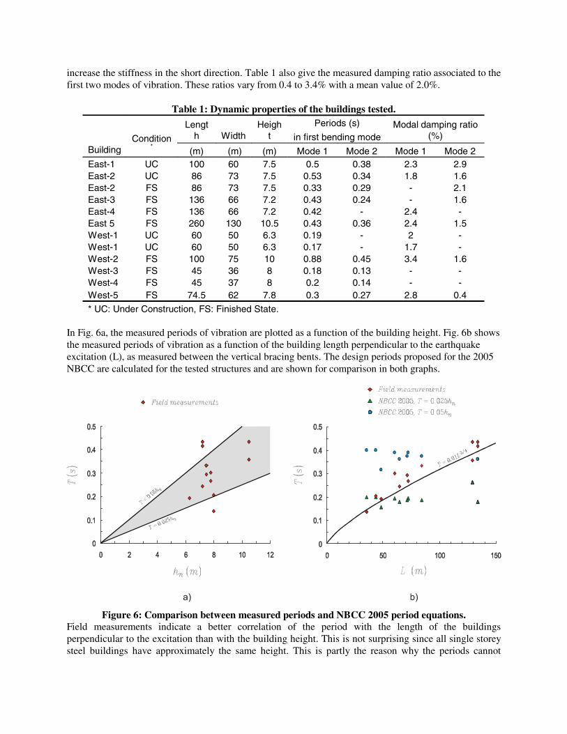
* UC: Under Construction, FS: Finished State. In Fig. 6a, the measured periods of vibration are plotted as a function of the building height. Fig. 6b shows the measured periods of vibration as a function of the building length perpendicular to the earthquake excitation (L), as measured between the vertical bracing bents. The design periods proposed for the 2005 NBCC are calculated for the tested structures and are shown for comparison in both graphs.
Figure 6: Comparison between measured periods and NBCC 2005 period equations. Field measurements indicate a better correlation of the period with the length of the buildings perpendicular to the excitation than with the building height. This is not surprising since all single storey steel buildings have approximately the same height. This is partly the reason why the periods cannot
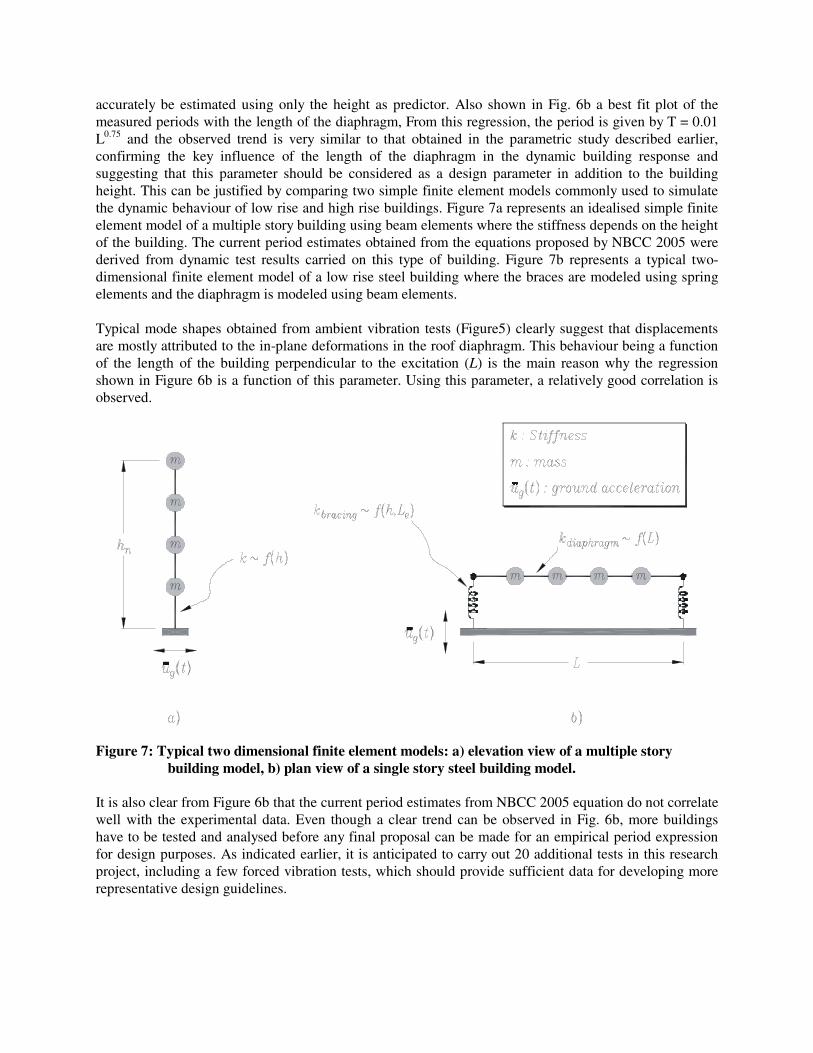
accurately be estimated using only the height as predictor. Also shown in Fig. 6b a best fit plot of the measured periods with the length of the diaphragm, From this regression, the period is given by T = 0.01 L0.75 and the observed trend is very similar to that obtained in the parametric study described earlier, confirming the key influence of the length of the diaphragm in the dynamic building response and suggesting that this parameter should be considered as a design parameter in addition to the building height. This can be justified by comparing two simple finite element models commonly used to simulate the dynamic behaviour of low rise and high rise buildings. Figure 7a represents an idealised simple finite element model of a multiple story building using beam elements where the stiffness depends on the height of the building. The current period estimates obtained from the equations proposed by NBCC 2005 were derived from dynamic test results carried on this type of building. Figure 7b represents a typical two-dimensional finite element model of a low rise steel building where the braces are modeled using spring elements and the diaphragm is modeled using beam elements. Typical mode shapes obtained from ambient vibration tests (Figure5) clearly suggest that displacements are mostly attributed to the in-plane deformations in the roof diaphragm. This behaviour being a function of the length of the building perpendicular to the excitation (L) is the main reason why the regression shown in Figure 6b is a function of this parameter. Using this parameter, a relatively good correlation is observed.
Figure 7: Typical two dimensional finite element models: a) elevation view of a multiple story
building model, b) plan view of a single story steel building model. It is also clear from Figure 6b that the current period estimates from NBCC 2005 equation do not correlate well with the experimental data. Even though a clear trend can be observed in Fig. 6b, more buildings have to be tested and analysed before any final proposal can be made for an empirical period expression for design purposes. As indicated earlier, it is anticipated to carry out 20 additional tests in this research project, including a few forced vibration tests, which should provide sufficient data for developing more representative design guidelines.
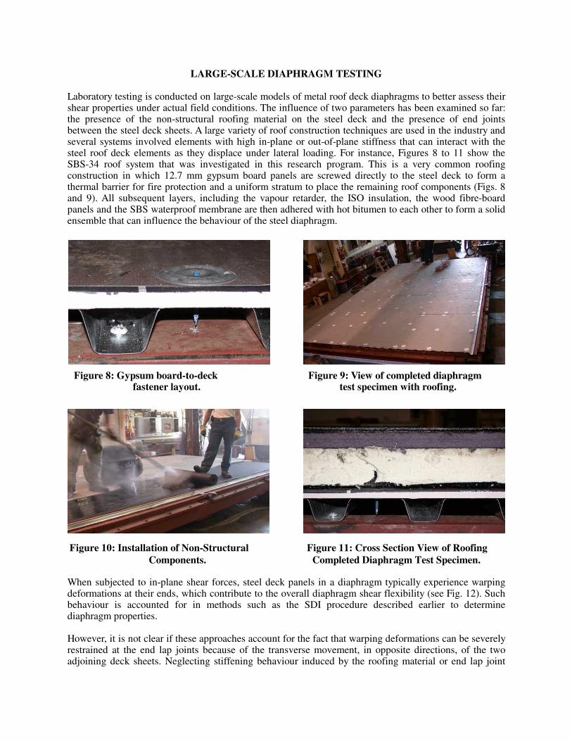
LARGE-SCALE DIAPHRAGM TESTING Laboratory testing is conducted on large-scale models of metal roof deck diaphragms to better assess their shear properties under actual field conditions. The influence of two parameters has been examined so far: the presence of the non-structural roofing material on the steel deck and the presence of end joints between the steel deck sheets. A large variety of roof construction techniques are used in the industry and several systems involved elements with high in-plane or out-of-plane stiffness that can interact with the steel roof deck elements as they displace under lateral loading. For instance, Figures 8 to 11 show the SBS-34 roof system that was investigated in this research program. This is a very common roofing construction in which 12.7 mm gypsum board panels are screwed directly to the steel deck to form a thermal barrier for fire protection and a uniform stratum to place the remaining roof components (Figs. 8 and 9). All subsequent layers, including the vapour retarder, the ISO insulation, the wood fibre-board panels and the SBS waterproof membrane are then adhered with hot bitumen to each other to form a solid ensemble that can influence the behaviour of the steel diaphragm.
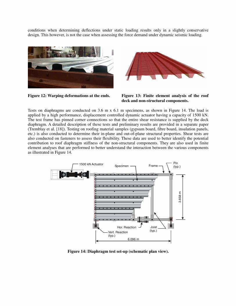
When subjected to in-plane shear forces, steel deck panels in a diaphragm typically experience warping deformations at their ends, which contribute to the overall diaphragm shear flexibility (see Fig. 12). Such behaviour is accounted for in methods such as the SDI procedure described earlier to determine diaphragm properties. However, it is not clear if these approaches account for the fact that warping deformations can be severely restrained at the end lap joints because of the transverse movement, in opposite directions, of the two adjoining deck sheets. Neglecting stiffening behaviour induced by the roofing material or end lap joint
Figure 8: Gypsum board-to-deck Figure 9: View of completed diaphragm fastener layout. test specimen with roofing.
Figure 10: Installation of Non-Structural Figure 11: Cross Section View of Roofing Components. Completed Diaphragm Test Specimen.
conditions when determining deflections under static loading results only in a slightly conservative design. This however, is not the case when assessing the force demand under dynamic seismic loading.
Figure 12: Warping deformations at the ends. Figure 13: Finite element analysis of the roof
deck and non-structural components. Tests on diaphragms are conducted on 3.6 m x 6.1 m specimens, as shown in Figure 14. The load is applied by a high performance, displacement controlled dynamic actuator having a capacity of 1500 kN. The test frame has pinned corner connections so that the entire shear resistance is supplied by the deck diaphragm. A detailed description of these tests and preliminary results are provided in a separate paper (Tremblay et al. [18]). Testing on roofing material samples (gypsum board, fibre board, insulation panels, etc.) is also conducted to determine their in-plane and out-of-plane structural properties. Shear tests are also conducted on fasteners to assess their flexibility. These data are used to better identify the potential contribution to roof diaphragm stiffness of the non-structural components. They are also used in finite element analyses that are performed to better understand the interaction between the various components as illustrated in Figure 14.
6.096 m
1500 kN Actuator
Joist(typ.)
Hor. Reaction
Specimen FramePin(typ.)
Vert. Reaction(typ.)
3.6
58 m
Figure 14: Diaphragm test set-up (schematic plan view).
CONCLUSIONS This paper outlines an on-going joint research program that is being carried out to better understand the dynamic response of low-rise steel structures such that advanced analytical dynamic analysis procedures can be used safely and efficiently in seismic design. A parametric study showed that typical structures designed according to modern building code provisions can have a fundamental period of vibration that is much longer than that assumed in the calculations, suggesting that reduced design loads could be specified for those structures. The study indicated that the building height and the length of the roof diaphragm in the direction perpendicular to the motion equally contribute to increasing the period of a structure. The type of vertical bracing system and the magnitude of the design seismic loads also affect the period values. The research project involves a large field test program to determine the natural frequencies, mode shapes and damping ratios of actual buildings located in both eastern and western regions of Canada. The test procedure was summarized and comments were provided on preliminary tests results in light of the parametric study. Typically, the measured periods appear to be in accordance with current code provisions and significantly shorter than that obtained from simplified analytical model predictions. Experimental work is also conducted in a laboratory setting to determine the structural properties of metal roof deck diaphragms in the as-built condition, i.e. including the presence of the roofing material and end lap joints between adjacent deck sheets. Preliminary results show that both parameters can contribute to an increase of the stiffness of typical roof diaphragms. Additional in-situ and laboratory testing will be conducted in the subsequent phases of the project. In addition, analytical work will be conducted to develop numerical modelling techniques capable of reproducing data from field testing.
ACKNOWLEDGEMENTS
This research was supported by the Natural Sciences and Engineering Research Council of Canada. The collaboration of the Canam Manac Group, the Canadian Institute of Steel Construction, and the technical staff at the Structural Engineering Laboratory at Ecole Polytechnique, Sherbrooke University and University of British Columbia is acknowledged.
REFERENCES
1. CSSBI. “Design of steel deck diaphragms.” Canadian Sheet Steel Building Institute, Willowdale, ON, 1991.
2. SDI. “Diaphragm design manual, 2nd Edition.” Steel Deck Institute, Canton, FL, 1991. 3. Davies, J.M., Bryan, E.R. “Manual of stressed skin diaphragm design.” John Wiley and Sons Inc.,
New York, NY, 1982. 4. Dubina, D., Zaharia, R. and Georgescu, M. “Stress skin design of single-storey steel buildings in
seismic areas.” Proceedings of the STESSA 97 Conference on the Behaviour of Steel Structures in Seismic Areas. Kyoto, Japan, 1997: 426-433.
5. Jain, S.K. and Jennings, P.C. “Analytical models for low-rise buildings with flexible roof diaphragms. Earthquake Engineering and Structural Dynamics 1985; 13: 225-241.
6. Kunnath, S.K., Pahahshahi, N. and Reinhorn, A.M. Seismic response of RC buildings with inelastic floor diaphragms. ASCE Journal of Structural Engineering 1991; 117: 1218-1237.
7. Medhekar, M.S. “Seismic evaluation of steel buildings with concentrically braced frames.” Ph.D. Thesis, Dept. of Civil and Environmental Engineering, University of Alberta, Edmonton, AL, 1997.
8. Naman, S.K. and Goodno, B.J. “Seismic evaluation of low rise steel building.” Engineering Structures 1986; 8, 9-16.
9. Tena-Colunga, Abrams, D.P. “Seismic behavior of structures with flexible diaphragms.” ASCE Journal of Structural Engineering 1996; 122, 439-445.
10. Tremblay, R. and Stiemer, S.F. “Seismic behavior of single-storey steel structures with flexible diaphragm”. Canadian Journal of Civil Engineering 1996; 23: 49-62.
11. Tremblay, R., Rogers, C.A., and Nedisan, C. “Seismic torsional response of single-storey steel structures with flexible roof diaphragms”. Proceedings of Advances in Structures - Steel, Concrete, Composite and Aluminium 2003 Conference, Sydney, Australia. Paper No. 278. 2003.
12. Goel, R.K. and Chopra, A.K. “Period formulas for moment-resisting frame buildings.” ASCE Journal of Structural Engineering 1997; 123, 11: 1454-1461.
13. Tremblay, R. “Fundamental period of vibration of braced steel frames for seismic design.” Earthquake Spectra 2004 (submitted).
14. Tremblay, R and Bérair, T. “Shake table testing of low-rise steel buildings with flexible roof diaphragms”. Proceedings of the 8th Canadian Conference on Earthquake Engineering, Vancouver, Canada. 585-590. 1999.
15. Tremblay, R., Bérair, T., and Filiatrault, A. “Experimental Behaviour of Low-Rise Steel Buildings with Flexible Roof Diaphragms. Proc. 12th World Conference on Earthquake Engineering, Auckland, NZ. Paper No. 2567. 2000.
16. Ventura, C.E. “Ambient vibration test of the Safeway store.” Report by the UBC Ambient Vibration Team, Dept. of Civil Engineering, University of British Columbia, Vancouver, BC, 1995.
17. Bakhtavar, M.S. 2000. Seismic behaviour & computer modelling of low-rise steel frame structures. Technical Report No. 00-01, Earthquake Engineering Research Facility, Dept. of Civil Engineering, University of British Columbia, Vancouver, BC, 2000.
18. Tremblay, R., Rogers, C.A., Yang, W., and Martin, E. “Ductile design of steel roof deck diaphragms for earthquake resistance” Proceedings of the 13th World Conference on Earthquake Engineering, Vancouver, Canada. Paper No. 1997.
19. Heidebrecht, A.C. “Overview of NBCC 2005 seismic provisions. Canadian Journal of Civil Engineering 2003; 30, 241-254.
20. NRCC. “NBCC 2005 - Part 4 Structural Design - Draft January 2004.” National Research Council of Canada, Ottawa, ON, 2004.
21. CSA. “CSA-S16-01, Limit States Design of Steel Structures”. Mississauga, ON, 2001. 22. Adams, J. and Halchuk, S. “Fourth generation seismic maps of Canada: Values for over 650
Canadian localities intended for the 2005 National Building Code of Canada, Geological Survey of Canada Open File 4459, National Earthquake Hazards Program, Geological Survey of Canada, Natural Resources Canada, Ottawa, ON, 2003.
23. Paultre, P. and Proulx, J. 1997. Dynamic Testing of Large Scale Structures, Journal of the International Association for Bridge and Structural Engineering (IABSE), 7(1), 29-34.
24. Lamarche, C-P., Mousseau S., Paultre, P., Proulx, J. “A Comparison of Ambient and Forced-Vibration Testing of a Full Scale Concrete Structure.” Proceedings of the 22nd International Conference on Modal Analysis (IMAC XXII), Dearborn, USA, 2004: paper #327.