Embed Size (px)
Citation preview

Journal of Engineering Science and Technology Vol. 8, No. 4 (2013) 457 - 471 © School of Engineering, Taylor’s University
457
EXPERIMENTAL EVALUATION OF NUMERICAL MODELS TO REPRESENT THE STIFFNESS OF LAMINATED ROTOR CORES
IN ELECTRICAL MACHINES
HIDERALDO L. V. SANTOS1, MARCO A. LUERSEN
2,*,
CARLOS A. BAVASTRI3
1WEG Electrical Equipments S.A., Jaraguá do Sul, SC, Brazil 2Structural Mechanics Laboratory (LaMEs), Federal University of Technology -
Paraná (UTFPR), Curitiba, PR, Brazil 3Mechanical Engineering Department, Federal University of Paraná (UFPR),
Curitiba, PR, Brazil
*Corresponding Author: [email protected]
Abstract
Usually, electrical machines have a metallic cylinder made up of a compacted
stack of thin metal plates (referred as laminated core) assembled with an
interference fit on the shaft. The laminated structure is required to improve the
electrical performance of the machine and, besides adding inertia, also enhances
the stiffness of the system. Inadequate characterization of this element may lead to
errors when assessing the dynamic behavior of the rotor. The aim of this work
was therefore to evaluate three beam models used to represent the laminated core
of rotating electrical machines. The following finite element beam models are
analysed: (i) an “equivalent diameter model”, (ii) an “unbranched model” and (iii) a “branched model”. To validate the numerical models, experiments are
performed with nine different electrical rotors so that the first non-rotating natural
frequencies and corresponding vibration modes in a free-free support condition
are obtained experimentally. The models are evaluated by comparing the natural
frequencies and corresponding vibration mode shapes obtained experimentally with those obtained numerically. Finally, a critical discussion of the behavior of
the beam models studied is presented. The results show that for the majority of the
rotors tested, the “branched model” is the most suitable
Keywords: Rotordynamics, Laminated core, Electrical machines, Natural frequencies.

458 H. L. V. Santos et al.
Journal of Engineering Science and Technology August 2013, Vol. 8(4)
Nomenclatures
CG Center of gravity
Ecore Equivalent Young’s modulus of the laminated core (used in
model 2), GPa
HCO Height of the yoke of the rotor plate, m
Kc Total stiffness of the sprigs used in model 3, N/m
LAC Length of the shorting rings, m
LCH Total length of the laminated core, m
LSHAFT Length of the shaft, m
MCH Mass of the laminated core, kg
MSHAFT Mass of the shaft, kg
MT Total mass of the core, kg
pt Increase applied to the shaft’s diameter (varies from 0 to 1)
RE Radius of the shaft in the core region, m
Greek Symbols
∆φE Increase in the diameter of the shaft to simulate the stiffening
effect, m
φAC Outer diameter of the shorting rings, m
φCH Diameter of the laminated core, m
φCO Diameter of the yoke of the plates in the core, m
φE Diameter of the shaft at the core position, m
φEQV Equivalent shaft diameter at the core position, m
λi Eigenvalue ( 2
i iλ ω= )
ρE Mass density of the shaft’s material, kg/m3
ωi i-th natural frequency, rad/s
1. Introduction
In the mechanical design of an electrical machine, all the machine’s functional
requirements must be well defined to ensure its durability, operating reliability,
performance and environmental acceptability. The majority of these requirements
are inextricably linked to the vibration behavior of the machine and are usually
addressed by international standards [1]. The existing body of knowledge about
rotordynamics has made possible significant advances in the design of rotating
systems to satisfy these standards [1-3]. Nevertheless, there is still scope for
improvement of certain critical aspects. Specifically, there are few studies in the
literature that address the way in which the laminated cores of electrical machines
are modeled, despite the importance of this issue for the dynamics of the system.
In general, it is difficult to determine how much stiffness a lamination stack
imparts to the rotor when it is mounted on the shaft with an interference fit. The
API 684 standard [4] states that it is a challenge to determine the amount of
stiffness a lamination stack adds to the shaft and recommends, as an
approximation, that the outer diameter of the shaft in the region of the stack be
considered to have increased so that the additional mass is equal to the mass of
the laminated core. This new “equivalent” diameter is used to take into account
the increased stiffness of the shaft imparted by the lamination stack.

Experimental Evaluation of Numerical Models of Laminated Rotor Cores 459
Journal of Engineering Science and Technology August 2013, Vol. 8(4)
Kim and Kim [5] presented the results of a numerical and experimental study of
the relationship between the lamination pressure used to assemble the lamination
stack and the percentage increase that must be applied to the actual diameter of the
shaft to take into account the stiffening effect. The authors used a 642 kg rotor
consisting of just the shaft and laminate without slots for the squirrel cage bars as a
test rig. The interference between the outer diameter of the shaft and the inner
diameter of the lamination stack was 0.01mm. Ignoring the effect of rotation and
temperature, they recommended that the shaft diameter at the core region be
increased from 17% to 23% of the value of the difference between the outer and
inner core diameters. Their conclusions were based on an experiment that
determined the first three natural frequencies and corresponding mode shapes of the
rotor in a free-free condition. The modal analysis was repeated for different
lamination pressures, and the natural frequencies were obtained for each condition.
The authors noticed that the natural frequencies increased with increasing
lamination pressure. This increase was not directly proportional to the pressure, and
for high lamination pressures the natural frequencies did not change significantly.
Chen et al. [6] described a more comprehensive method for modeling the whole
electrical machine. They used a parallel-beam (shaft and lamination stack) finite
element model to represent a rotor with a laminated core. In this model the elements
are connected node to node by springs. The properties of the lamination stack material
were adjusted using experimental measurements of the natural frequencies of the
rotor in a free-free condition. Garvey et al. [7] suggested modeling the laminated
core as an orthotropic material by establishing a new definition of the stress-strain
state that considers the flexibility between the sheets of the core. Two
configurations were investigated. In the first, the elements that represent the shaft
and the stack are superimposed so that their ends are connected by the same nodes,
in an approach known as the “unbranched model”. The second configuration - the
“branched model” - uses elements in parallel connected by springs and dampers in
an approach similar to that described by Chen et al. [6].
The initial objective of this work was to verify whether different geometries
and/or vibration modes of squirrel-cage rotors can be represented with the same
beam model using only one unknown a priori parameter value, which is
determined experimentally. We evaluated the following three versions of
equivalent beam models: (i) a model using an equivalent shaft diameter in the
core region, referred to here as the “equivalent diameter model”, (ii) a model
using different finite elements to represent the laminated core and the shaft, with
their ends connected by the same nodes, referred to as the “unbranched model”
and (iii) a model similar to that described in (ii) but with all the ends of the shaft
and laminated elements connected by springs, known, for this reason, as the
“branched model”. Each model is detailed in Section 2. The general objective of
this work was therefore to implement the three equivalent beam models using the
finite element method and carry out experiments to evaluate the behavior of the
models for squirrel cage rotors with different geometries. Because of the
difficulties of carrying out experiments in rotating systems, the experimental
analysis was performed in non-rotating conditions. The models were evaluated by
comparing the natural frequencies and corresponding vibration mode shapes
obtained experimentally in a free-free support condition with those obtained by
finite element analysis. It is known that the rotor rotation and the supports will
change the dynamic characteristics of the systems, but this work intends to be a
first step done by the authors in this research area.

460 H. L. V. Santos et al.
Journal of Engineering Science and Technology August 2013, Vol. 8(4)
2. Description of the Numerical Models
2.1. Model 01: equivalent diameter
The best-known and most widely used approach for modeling any part assembled
on a shaft, including a laminated core, is to increase the diameter of the shaft in
that region. The new diameter is referred to as the “equivalent diameter”. The
laminated core is thus considered part of the shaft, adding mass and inertia and
contributing to the total stiffness of the rotor [5].
The laminated core consists of a cylinder made up of stacked sheets with a total
length LCH, diameter φCH and mass MCH, the latter including the mass of the copper or
aluminium bars, Fig. 1(a). The two shorting rings at both ends of the laminated core
are identical and are of length LAC, outer diameter φAC and mass MAC; their center of
gravity (CG) is at a distance d from the corresponding end plate of the stack.
In model 01, the shaft diameter φE at the core position is increased by ∆φE , Fig. 1(b). This increase in the diameter of the shaft simulates the stiffening effect
of the laminated stack, in an approach similar to that described by Lalanne and
Ferraris [2] to take into account the effect of discs assembled on the shaft. The
new diameter in the core region is referred to as φEQV and is given by
( )EQV E 1 ptφ φ= + (1)
where pt is the increase applied to the diameter of the shaft and varies from 0
to 1 (corresponding to 0% and 100% of the actual diameter of the shaft,
respectively). The rest of the laminated stack - the outer core diameter minus the
equivalent diameter (φCH - φEQV) - is then divided into N discs whose mass and inertia are concentrated at the shaft nodes created in the stack region, while the
mass and inertia values of the shorting rings are translated to the end plates of the
stack, Fig. 1(b). This assembly is converted into an equivalent beam system with
concentrated mass and inertia elements calculated to maintain the original mass
and inertia of the whole system, Fig. 1(c).
Fig. 1. Sequence of Steps Required to Represent the Laminated Core by an
Equivalent Shaft Diameter: (a) Solid Model, (b) Equivalent Solid Model and
Equivalent Beam Model (c).
x
y
(a)
(b)
(c)
MAC, I AC
MAC, I AC
φCH
LCH
MCH
LAC
φAC
d
MAC
φEφEQV = φE + ∆φE
φCH
MD , ID

Experimental Evaluation of Numerical Models of Laminated Rotor Cores 461
Journal of Engineering Science and Technology August 2013, Vol. 8(4)
In the model described above, the only unknown parameter or variable is pt,
which defines the equivalent diameter in the core region. The other parameters in
the model can be obtained directly from the rotor characteristics. Kim and Kim
[5] found experimentally that pt varied from 0.28 to 0.36. They also established a
second method of determining the equivalent diameter, using more information
about the rotor characteristics and the following equation:
( )EQV E CH E ptφ φ φ φ= + − (2)
Using this definition, the authors found experimentally that pt varied from
0.17 to 0.23 depending on the mode of vibration of the rotor. In both approaches,
the value of pt changes according to the rotor being used and the natural vibration
mode shape of the rotor.
According to the recommendation contained in [4] (API Standard, mentioned
in Section 1), the increase in diameter must be such that the total mass of the
laminated core MCH is preserved, so that
( )
2 2
EQV E
E CH CHL M4
π φ φρ
−= (3)
where
2CH
EQV E
E CH
4M
Lφ φ
πρ= + (4)
In this case, EQVφ is not expressed as a function of pt.
2.2. Model 02: unbranched model
In this approach, the laminated stack is modeled as a continuous hollow cylinder
with equivalent elastic properties to simulate the effect of the stack [7]. If the
cylinder is assumed to be assembled on the shaft with an interference fit, the
resulting cross section will be a compound one with two materials, Fig. 2(b). To
convert this system to a finite element model, in the core region we used two
superimposed beam elements joined at their ends by the same node, Fig. 2(c). For
both elements the Timoshenko beam model with isotropic material was used,
although Garvey et al. [7] suggested a new formulation for the elements of the
laminates, using an equivalent orthotropic material. In model 02 the effect of the
laminated stack can be achieved by changing the Young’s modulus of the
laminated cylinder elements Ecore. Using the approach described above, the only
unknown parameter or model variable is Ecore, the other model parameters being
obtained directly from the rotor characteristics.
2.3. Model 03: branched model
In the branched model, the stack and shaft assembly is represented by a dual rotor
system connected node-to-node by springs with a total stiffness Kc, Fig. 3. The
laminated stack is again modeled with the same kind of beam elements used for
the shaft and is represented as a hollow cylinder with the same isotropic material
properties as the shaft. The lamination effect can be adjusted by varying Kc, the
only parameter in this model.

462 H. L. V. Santos et al.
Journal of Engineering Science and Technology August 2013, Vol. 8(4)
Fig. 2. Schematic Diagram of Lamination Stack
Represented as a Parallel Beam (Unbranched Model).
Fig. 3. Dual Rotor Arrangement for the Branched Model.
2.4. Numerical implementation
The three models described above were implemented using the commercial finite
element software ANSYS rev. 11.0. A macro was developed in APDL (Ansys
Parametric Design Language, see [8]) to build a parametric model for easy post-
processing analysis. The basic data used for the rotor were the lengths of the shaft
steps; the outer and inner diameter of each shaft step; the Young’s modulus,
Poisson’s ratio and density for the shaft material; and the total mass of the
lamination core. Three finite element types were used to represent the system:
class C1 Timoshenko’s beam elements ([9]) for the shaft and laminated core in
models 02 and 03; point mass elements (with mass and inertia moments) to
x
y
(a)
(b)
(c)
MAC, I AC
shaft Core – Ecore
MAC, I AC
x
y
(a)
(b)
MAC, I AC
shaft
Laminated core – Ecore
MAC, I AC
Kc
Experimental Evaluation of Numerical Models of Laminated Rotor Cores 463
Journal of Engineering Science and Technology August 2013, Vol. 8(4)
represent the discs in model 01; and one-dimensional spring elements to represent
the interface between the shaft and the laminated core in model 03.
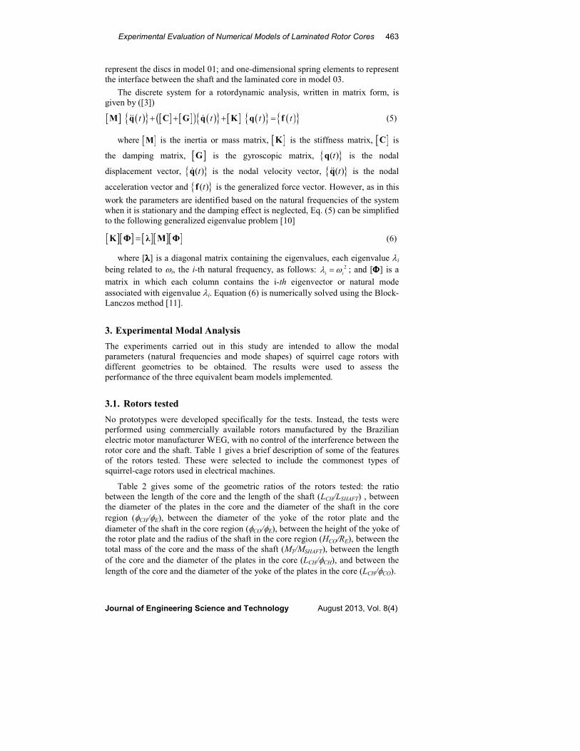
The discrete system for a rotordynamic analysis, written in matrix form, is
given by ([3])
[ ] ( ){ } [ ] [ ]( ) ( ){ } [ ] ( ){ } ( ){ } t t t t+ + + =M q C G q K q f&& & (5)
where [ ]M is the inertia or mass matrix, [ ]K is the stiffness matrix, [ ]C is
the damping matrix, [ ]G is the gyroscopic matrix, { }( )tq is the nodal
displacement vector, { }( )tq& is the nodal velocity vector, { }( )tq&& is the nodal
acceleration vector and { }( )tf is the generalized force vector. However, as in this
work the parameters are identified based on the natural frequencies of the system
when it is stationary and the damping effect is neglected, Eq. (5) can be simplified
to the following generalized eigenvalue problem [10]
[ ][ ] [ ][ ][ ]=K Φ λ M Φ (6)
where [λλλλ] is a diagonal matrix containing the eigenvalues, each eigenvalue λi
being related to ωi, the i-th natural frequency, as follows: 2
i iλ ω= ; and [ΦΦΦΦ] is a
matrix in which each column contains the i-th eigenvector or natural mode
associated with eigenvalue λi. Equation (6) is numerically solved using the Block-Lanczos method [11].
3. Experimental Modal Analysis
The experiments carried out in this study are intended to allow the modal
parameters (natural frequencies and mode shapes) of squirrel cage rotors with
different geometries to be obtained. The results were used to assess the
performance of the three equivalent beam models implemented.
3.1. Rotors tested
No prototypes were developed specifically for the tests. Instead, the tests were
performed using commercially available rotors manufactured by the Brazilian
electric motor manufacturer WEG, with no control of the interference between the
rotor core and the shaft. Table 1 gives a brief description of some of the features
of the rotors tested. These were selected to include the commonest types of
squirrel-cage rotors used in electrical machines.
Table 2 gives some of the geometric ratios of the rotors tested: the ratio
between the length of the core and the length of the shaft (LCH/LSHAFT) , between
the diameter of the plates in the core and the diameter of the shaft in the core
region (φCH/φE), between the diameter of the yoke of the rotor plate and the
diameter of the shaft in the core region (φCO/φE), between the height of the yoke of the rotor plate and the radius of the shaft in the core region (HCO/RE), between the
total mass of the core and the mass of the shaft (MT/MSHAFT), between the length
of the core and the diameter of the plates in the core (LCH/φCH), and between the
length of the core and the diameter of the yoke of the plates in the core (LCH/φCO).

464 H. L. V. Santos et al.
Journal of Engineering Science and Technology August 2013, Vol. 8(4)
Table 1. Some Characteristics of the Rotors Tested.
(*) The first three figures are associated with rotor size. The next two figures, in Roman numerals, are
associated with the number of poles and speed of rotation (for example, IIP corresponds to a rotor
speed of 3600rpm, and IVP to a rotor speed of 1800rpm)
Table 2. Some Geometric Ratios of the Rotors Tested.
3.2. Description of the experiments
All the rotors were tested in a free-free condition. Figure 4 shows the 560IIP
rotor, which weighs approximately 2 tons, suspended by slings and a hoist. Data
acquisition was performed using a Brüel & Kjær Type 3560C PULSETM four-
channel data acquisition unit. Excitation was provided with the aid of ENDEVCO
modal hammers: model 2203-5 for the 225IIP and 250IVP rotors, and model
8208 for the remaining ones1. The vibration peak was measured with a model
752A12 TEDS accelerometer, also from ENDEVCO.
1 The type of the hammer used is directly related to the mass of the rotor being tested.
Above a certain mass, the 8208 hammer had to be used, as this is suitable for heavy
structures.
Rotor
identification
(*)
Mass
(kg)
Rotor
characteristics
225IIP 70.0
Rotors with continuous aluminium
bars, without ventilation channels
(continuous core)
250IVP 141.0
355IIP(A) 355.0
355IIP(B) 367.0
355IIP(C) 378.0
315IIP 389.0 Rotors with aluminium bars and axial
ventilation channels (continuous core)
400IIP 828.0 Rotors with copper bars and axial
ventilation channels (continuous core) 450IVP 1224.0
560IIP 1890.0 Rotors with copper bars and axial and
radial ventilation channels (spaced cores)
Rotor
identification
CH
SHAFT
L
L
CH
E
φ
φ
CO
E
φ
φ
CO
E
H
R
T
SHAFT
M
M
CH
CHL
φ
CO
CHL
φ
225IIP 0.24 2.58 1.56 0.56 1.32 0.86 2.82
250IVP 0.37 3.05 2.20 1.20 3.01 1.27 3.78
355IIP(A) 0.33 3.18 2.03 1.03 2.97 1.29 3.75
355IIP(B) 0.33 2.87 1.83 0.83 2.52 1.29 3.95
355IIP(C) 0.33 2.41 1.54 0.54 1.76 1.29 4.39
315IIP 0.31 2.21 1.68 0.68 1.42 0.00 6.17
400IIP 0.28 1.80 1.40 0.40 0.87 1.65 7.44
450IVP 0.31 2.07 1.67 0.67 1.21 1.87 7.25
560IIP 0.31 2.04 1.57 0.57 1.20 2.12 8.33

Experimental Evaluation of Numerical Models of Laminated Rotor Cores 465
Journal of Engineering Science and Technology August 2013, Vol. 8(4)
Fig. 4. Rotor Suspended for an Experimental
Test in a Free-Free Support Condition.
The rotors were discretized as shown in Fig. 5 for the 560IIP rotor. Excitation
was provided using a modal hammer at a point at the front of the shaft, Fig. 6,
while an accelerometer scanned the other points on the rotor to measure the
response. This ensures that the first vibration modes are obtained sequentially
because there will never be a node at the extremities of the beam (the rotor) for
the boundary conditions tested. Pulse Labshop software, which provides graphs of
FRF (frequency response function) and coherence, was used for the data
acquisition, and ME’scopeVES was used for the modal analysis. In all the
measurements, ten averages were used for the FRF with a resolution of 1Hz. On
average, the frequency range used extended from 10 Hz to 5 kHz. The signals
were obtained using a uniform window for the hammer force and an exponential
window for the response from the accelerometer.
Fig. 5. Positions of the Excitation and Response Points (Distances in mm).
Fig. 6. Excitation and Measurement on the 250IVP Rotor.

466 H. L. V. Santos et al.
Journal of Engineering Science and Technology August 2013, Vol. 8(4)
3.3. Extraction of the modal parameters
The inertance curves were obtained from the modal analysis using techniques
based on the theory described by Ewins [10]. The modal parameters were
extracted in the frequency domain, using all the inertance curves of all the degrees
of freedom (discrete measurement points) simultaneously. The minimum least
squares method was used to estimate the modal parameters [12]. Table 3 shows a
summary of the natural frequencies obtained experimentally for each rotor. The
number of frequencies and corresponding vibration modes obtained for each rotor
were defined by the frequency band in which the excitation of the modal hammer
could be kept relatively constant (deviation less than 3 dB). For this reason, four
modes could be obtained for some rotors, while for others only three were
obtained. Although the modal damping was obtained experimentally, it was
neglected in the numerical models.
Table 3. Natural Frequencies Obtained Experimentally (in Hz).
4. Comparison of Experimental and Numerical Results
4.1. Discrepancies between numerical and experimental results
The proposed beam models were evaluated by varying their parameters within a
pre-established range. The first natural frequencies with their corresponding modes
of vibration were then calculated. These frequencies and modes were compared
with the modes obtained experimentally to determine the percentage error in the
natural frequency calculated for each value of the parameter for a particular model
in relation to the corresponding experimental values. This was done for each of the
rotors and each beam model, and the error was plotted on a graph in each case, as
shown in Figs. 7, 8 and 9 for the 225IIP rotor. The lines marked with lozenges,
squares, crosses and triangles correspond to the variation (absolute value) in the
error of each first natural frequency, while the solid red line represents the average
error as a function of the parameter used in each model.
Figure 10 shows a comparison of the vibration modes obtained experimentally
and numerically using the three models in the minimum error condition for the
355IIP(A) rotor. It can be seen that all the modes obtained numerically match
those obtained experimentally.
Rotor Freq. #1 Freq. #2 Freq. #3 Freq. #4
225IIP 688 1203 2597 3039
250IVP 612 928 2169 2794
355IIP(A) 329 579 1290 -
355IIP(B) 395 683 1362 -
355IIP(C) 468 822 1384 -
315IIP 332 493 853 1140
400IIP 288 454 711 -
450IVP 167 302 527 710
560IIP 137 202 429 566

Experimental Evaluation of Numerical Models of Laminated Rotor Cores 467
Journal of Engineering Science and Technology August 2013, Vol. 8(4)
Fig. 7. Error in the Natural Frequencies for the 225IIP Rotor – Model 01.
Fig. 8. Error in the Natural Frequencies for the 225IIP Rotor – Model 02.
Fig. 9. Error in the Natural Frequencies for the 225IIP Rotor – Model 03.

468 H. L. V. Santos et al.
Journal of Engineering Science and Technology August 2013, Vol. 8(4)
Fig. 10. Comparison of the Mode Shapes for the 355IIP(A) Rotor.
4.2. Evaluation of the accuracy of the models
It can be seen that there are many points in the graphs in Figs. 7, 8 and 9 that
minimize the numerical error and exactly fit the natural frequencies for each rotor
mode shape but correspond to different parameter values. This indicates that the
stiffness effect changes for each mode when equivalent beam models are used to
represent rotors with laminated cores. In an ideal model, one would be able to use
a single parameter value to reproduce all the dynamic characteristics of a rotor.
Therefore, to evaluate how close to ideal the equivalent beam models are, the
following criterion is proposed: the less dispersed the parameter values that
minimize the error in each mode shape, the more accurate will be the equivalent
model for a given rotor.

Experimental Evaluation of Numerical Models of Laminated Rotor Cores 469
Journal of Engineering Science and Technology August 2013, Vol. 8(4)
Based on the graphs above (and the corresponding graphs for the other rotors),
we can use the average error curve to obtain information about the accuracy of the
model. The accuracy of the equivalent model will therefore be determined by the
value of the minimum average error, which is henceforth referred to as minimum
error. Accordingly, the smaller the minimum error, the more accurate is the
model. Table 4 shows the minimum error values obtained for each model for each
rotor tested and the number of modes considered for each rotor. According to
these results, model 03 is the most accurate for almost all the rotors tested (six of
the nine). Additionally, we can infer that models 01 and 02 can be considered
equal in terms of accuracy. This conclusion was reported by Garvey et al. [7],
who state that the branched model is quite appropriate for representing rotors with
laminated cores.
Table 4. Minimum Error in the Natural
Frequencies for Each Equivalent Beam Model.
Rotor Model 01 Model 02 Model 03 No. of modes
225IIP 6.4% 5.8% 2.1% 04
250IVP 12.5% 10.2% 6.0% 04
355IIP(A) 9.2% 8.5% 1.9% 03
355IIP(B) 6.8% 6.1% 1.8% 03
355IIP(C) 2.7% 2.6% 1.2% 03
315IIP 3.1% 2.3% 3.7% 04
400IIP 1.9% 1.7% 0.3% 03
450IVP 3.0% 2.1% 4.4% 04
560IIP 3.6% 3.2% 4.0% 04
Since the final objective is to determine whether the same beam model can be
used to represent various rotor geometries without having to identify the
parameters for each case experimentally, the information on accuracy is
incomplete. The model must also be sufficiently robust for its characteristics not
to change substantially as the input parameters are changed when different types
of rotors are being modeled. The following section therefore describes the second
criterion used in this paper to evaluate the equivalent beam models.
4.3. Evaluation of the robustness of the models
The following robustness criterion was used in this work: using a single
parameter value for the equivalent beam model, is the model still capable of
calculating the first natural frequencies of all rotors accurately?
Table 5 shows the parameter values corresponding to the minimum error
condition shown in Table 4 for each model and rotor. The average of these
parameter values for all the rotors for a particular model is then used as a fixed
value to recalculate the natural frequencies. The new average error values for the
N first natural frequencies are shown in Table 6. It can be seen that for model 03
the average error remains below 5% in almost all the rotors tested (six of the nine)
using only one value for the parameter for this model. The exceptions were the
250IVP and 450IVP rotors.

470 H. L. V. Santos et al.
Journal of Engineering Science and Technology August 2013, Vol. 8(4)
Table 5. Parameter Values at the Minimum Error.
Rotor
Model
01
pt (%)
Model 02
Ecore
(GPa)
Model
03
Kc (N/m)
225IIP 23.9% 5.1 7.6 x10¹⁰
250IVP 55.2% 14.0 9.9 x1009
355IIP(A) 42.4% 6.2 5.6 x10¹⁰
355IIP(B) 45.6% 9.7 1.7 x10¹¹
355IIP(C) 29.6% 10.0 4.9 x10¹⁰
315IIP 30.0% 17.0 3.3 x10¹⁰
400IIP 15.6% 16.0 1.8 x10¹⁰
450IVP 10.0% 6.2 1.1 x10¹⁰
560IIP 28.8% 21.0 4.1 x10¹⁰
Average 31.2% 12.0 5.1 x10¹⁰
Table 6. Average Error in the Natural Frequencies for
the N First Natural Frequencies with a Fixed Parameter.
Rotor Model 01 Model 02 Model 03
225IIP 7.4% 9.3% 2.4%
250IVP 20.1% 11.5% 9.7%
355IIP(A) 15.% 10.6% 2.1%
355IIP(B) 13.5% 6.7% 2.8%
355IIP(C) 3.2% 3.3% 1.3%
315IIP 3.3% 4.5% 4.0%
400IIP 6.7% 2.5% 3.4%
450IVP 16.1% 5.8% 13.3%
560IIP 3.8% 5.7% 4.2%
5. Concluding Remarks
In this work, three beam models for representing the dynamic influence of the
laminated core of electrical machine rotors were implemented and evaluated. The
models were evaluated by comparing the natural frequencies and mode shapes
obtained numerically and experimentally. Nine different squirrel-cage rotors were
used for the experiments. Two methods for evaluating the models were described.
In the first, a curve of mean error for all modes was plotted against the variable
parameter for each model. The minimum value of this curve was used to define
the accuracy of the beam model in question for each of the rotors tested. On
average, model 03 (the “branched model”) proved to be the most accurate in
reproducing the natural frequencies of the nine rotors tested. The second
evaluation method was based on the criterion of model robustness, i.e., whether a
single parameter value could be used in the model to represent all the rotors
tested. In the first method for evaluating the models, the value of the parameter at
minimum error for a particular model varied between rotors. The mean of these

Experimental Evaluation of Numerical Models of Laminated Rotor Cores 471
Journal of Engineering Science and Technology August 2013, Vol. 8(4)
parameter values for all the rotors was then used as a new fixed evaluation
parameter to recalculate the average error in the N first natural frequencies of a
given rotor. Model 03 proved to be the most robust in the majority of cases but
had a large error for two of the rotors analysed. Apart from these two exceptions,
this model had a mean error of less than 5% using a single parameter value.
Acknowledgement
The authors would like to thank the Brazilian funding agency FINEP under the
project PROMOVE 4931/06 and WEG Company for the financial support.
References
1. Ehrich, F.F. (2004). Handbook of rotordynamics (3nd Ed.). Florida: Krieger Publishing Company.
2. Lalanne, M.; and Ferraris, G. (1990). Rotordynamics prediction in engineering (1st ed.). England, John Wiley & Sons Ltd.
3. Wowk, V. (1994). Machinery vibration: Balancing. McGraw Hill, Inc., USA.
4. API 684 - American Petroleum Institute Standards (2005). API Recommended Practice 684: Rotordynamics tutorial - lateral critical speeds,
unbalance response, stability, train torsionals, and rotor balancing.
Washington, D.C.
5. Kim, Y.C.; and Kim, K.W. (2006). Influence of lamination pressure upon the stiffness of laminated rotor. JSME International Journal, 49(2), 426-431.
6. Chen, Y.S.; Cheng, Y. D.; Liao, J. J.; and Chiou, C.C. (2008). Development of a finite element solution module for the analysis of the dynamic behavior
and balancing effects of an induction motor system. Finite Elements in
Analysis and Design, 44(8), 483-492.
7. Garvey, S.D.; Penny, J.E.T.; Friswell, M.I.; and Lees, A.W. (2004). The stiffening effect of laminated rotor cores on flexible-rotor electrical
machines. In: IMECHE - International Conference on Vibrations in Rotating
Machinery, Swansea, UK, 193-202.
8. ANSYS User’s Manual, Version 11.0 (2008). Swanson Analysis Systems Inc. (SASI), Houston, PA.
9. Genta, G. (2005). Dynamics of rotating systems (1st Ed.). New York: Springer.
10. Ewins, D.J. (1984). Modal testing: Theory and practice (1st Ed.). Great Britain: Research Studies Press Ltd.
11. Bathe, K.J. (1996). Finite element procedures (1st Ed.). New Jersey: Prentice Hall.
12. ME’scopeVES Version 4.0.0.6 (2003). Operating Manual: Volume II - Reference. Vibrant Technology, Inc.