Embed Size (px)
Citation preview

Journal of Engineering Science and Technology Vol. 11, No. 3 (2016) 362 - 382 © School of Engineering, Taylor’s University
362
FLOW-INDUCED VIBRATION IN PIPES: CHALLENGESS AND SOLUTIONS - A REVIEW
M. SIBA1,2, W. WANMAHMOOD
1, M. ZAKI NUAWI
1, R. RASANI
1,
M. NASSIR3,*
1Department Mechanical and Material, Faculty of Engineering and Built Environment;
National University of Malaysia, Selangor, 43600 Bangi, Malaysia 2Institute of Technology-Baghdad, Foundation of Technical Education, Baghdad, Iraq
3Programe of Chemical Engineering, School of Engineering, Taylor’s University, Taylor's Lakeside Campus, No. 1 Jalan Taylor's, 47500, Subang Jaya, Selangor DE, Malaysia
*Corresponding Author: [email protected]
Abstract
The Flow-induced vibration has recently been the topic of experimental,
numerical, and theoretical studies. It was intended to implement better
applications for controlling the flow using orifice technique. Having the flow under control, the orifice becomes an instrument for measuring the flow. The
flow of all fluid such as water, oil, gas and vapours through an orifice was
tested and mathematical models were developed adequately. The basic theme
for these enormous studies was the need for the very accurate flow
measurements through orifices. All experimental, theoretical, numerical, and
analytical studies have agreed that there is more than one avenue to develop, modify, and enhance such measurements. However, one factor that affects the
flow measurements is the vibration which was not treated as required until the
mid-20th century due to enormous discoveries that damages could be rooted to
vibration. Researchers have studied vibration and then proposed mathematical
models in conjunction with the pressure and velocity measurements of the
flowing fluids and then the effect of the vibration, induced or not induced, has been under continuous investigation. This paper is an attempt to review the
previous studies regarding understanding the nature of the vibration and the
possible effects of vibration on the flow and on the piping structure in order to
limit the damage caused by the vibration. This study shows that the need for
more experimental studies and more comprehensive analytical approaches are,
in particular, very essential to develop better results.
Keywords: Orifice, Vibration, CFD and Vibration, Numerical analysis,
Navier-Stokes theorem.

Flow-Induced Vibration in Pipes: Challenges and Solutions: A Review 363
Journal of Engineering Science and Technology March 2016, Vol. 11(3)
1. Introduction
Ashley and Haviland, 1950 [1] studied the flow-induced vibration of the trans-
Arabian pipeline. This introductory study was followed by a series of other
studies through which the nature of the vibration was deeply investigated [2] and
then analysed theoretically and analytically [3, 4]. It was until mid-twentieth
century when the nuclear technology has emerged beside other energy sources,
vibration was found to be one of the most important factors that cause damages to
some parts of these power plants. The damage and possible causes were
documented by researchers, governmental institutions, and private agencies [5-8].
Since then, vibration and vibration-induced damages were reportedly and heavily
studied. These studies have been focusing on three different areas: experimental
[9-13], investigation using numerical analysis [14-17], and investigation using
simulation techniques [18-20]. The heavily investigation in power plant accidents
has its own impact on governments to set rules and regulations to avoid such
increasing number of unfortunate accidents. The rules are listed and implemented
in all power plants, aircrafts, military and civil ships, automobile, and many more.
Another confirmation for setting and monitoring these rules and regulations came
from the American Society of Mechanical Engineers (ASME) and the
International Organization for Standardization (ISO). Both non-governmental
agencies have issued a code to ensure safety measures [21, 22].
The vibration induced by flow through orifice has another impact on the flow
measurements which is considered as dangerous as the safety measures.
Traditionally, the orifice plate has been used as a device to control the flow rate in
piping systems. In industry, as well as in research, accurate measurements of the
flow rate are very crucial especially in pharmaceutical plants and refineries when
additives and/or catalysts are subjected to very sensitive measurements. To
successfully achieve precise flow measurements, the impact of the vibration
caused by pressure inside the pipes should be closely considered by studying its
impact experimentally, theoretically, and numerically. The vibration could cause
damages to the pipes or the pipe components [17]. Consequently, studying and
then analysing the vibration phenomena becomes an essential and important to
avoid such possible mishap [15, 17].
The fabrication, installation, and using the orifice plate for flow measurements
are very simple and inexpensive. Beside simple fabrication, orifices do not require
serious and lengthy maintenance which results in very low cost [16]. At this stage,
it is very important to mention that there are some, even limited, malfunctions
caused by orifice plate such as homogeneous fluid, turbulent flow (Re > 4000),
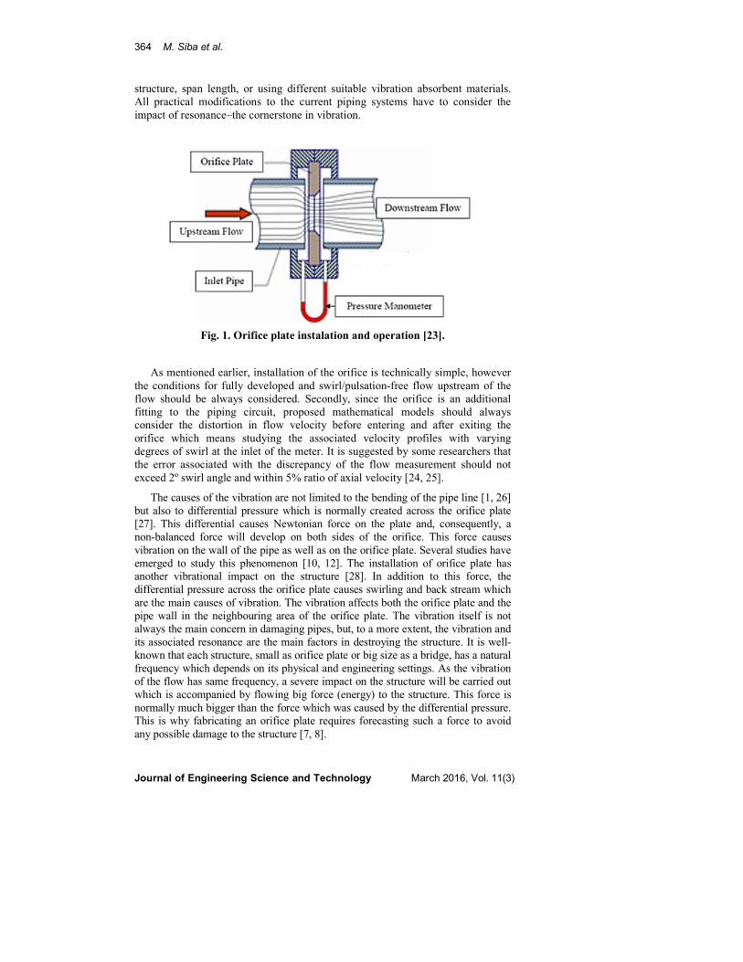
and causing vibrational resonance [3, 6, 7]. Figure 1 shows installation and
operation for a typical orifice plate.
Piping-induced vibration in industry represents the main drawback for the
simplicity of piping circuit establishment. Broken pipes, heavily continual
maintenance, and sudden erupted fire are the current challenges that are facing
pharmaceutical, refineries, and research labs. Within the last 30 years, the damage
due to inaccurate flow measurements, delay in production, and fire exceed
billions of dollars [8]. Avoiding such technical serious issues, the vibration, using
pressure techniques, should be tested and evaluated for precaution and possible
improvement. Having vibration determined, safety measures should be
implemented especially with excessive vibration by using enough support
364 M. Siba et al.
Journal of Engineering Science and Technology March 2016, Vol. 11(3)
structure, span length, or using different suitable vibration absorbent materials.
All practical modifications to the current piping systems have to consider the
impact of resonance–the cornerstone in vibration.
Fig. 1. Orifice plate instalation and operation [23].
As mentioned earlier, installation of the orifice is technically simple, however
the conditions for fully developed and swirl/pulsation-free flow upstream of the
flow should be always considered. Secondly, since the orifice is an additional
fitting to the piping circuit, proposed mathematical models should always
consider the distortion in flow velocity before entering and after exiting the
orifice which means studying the associated velocity profiles with varying
degrees of swirl at the inlet of the meter. It is suggested by some researchers that
the error associated with the discrepancy of the flow measurement should not
exceed 2º swirl angle and within 5% ratio of axial velocity [24, 25].
The causes of the vibration are not limited to the bending of the pipe line [1, 26]
but also to differential pressure which is normally created across the orifice plate
[27]. This differential causes Newtonian force on the plate and, consequently, a
non-balanced force will develop on both sides of the orifice. This force causes
vibration on the wall of the pipe as well as on the orifice plate. Several studies have
emerged to study this phenomenon [10, 12]. The installation of orifice plate has
another vibrational impact on the structure [28]. In addition to this force, the
differential pressure across the orifice plate causes swirling and back stream which
are the main causes of vibration. The vibration affects both the orifice plate and the
pipe wall in the neighbouring area of the orifice plate. The vibration itself is not
always the main concern in damaging pipes, but, to a more extent, the vibration and
its associated resonance are the main factors in destroying the structure. It is well-
known that each structure, small as orifice plate or big size as a bridge, has a natural
frequency which depends on its physical and engineering settings. As the vibration
of the flow has same frequency, a severe impact on the structure will be carried out
which is accompanied by flowing big force (energy) to the structure. This force is
normally much bigger than the force which was caused by the differential pressure.
This is why fabricating an orifice plate requires forecasting such a force to avoid
any possible damage to the structure [7, 8].
Flow-Induced Vibration in Pipes: Challenges and Solutions: A Review 365
Journal of Engineering Science and Technology March 2016, Vol. 11(3)
Theoretically, the calculations of the velocity, pressure, vorticity, and the
mechanical properties should be conducted based on Navier-Stokes (N-S)
equations [15] and subsequent models. Researchers in the last three decades have
developed and/or enhanced variety of software to study some complex structures
such as the flow through the orifice plate. N-S equations were, in part, simplified
to fit certain requirements and boundary conditions. However, more general
solutions require more sophisticated software such as Fluid Structure Interaction
(FSI) and Computational Fluid Dynamics (CFD). The flow-induced vibration is
studied using FSI technique while predicting the whistling of an orifice plate in a
flow duct was studied by CFD.
The flow-induced vibration is the core of this review. The study includes, but
not limited to, turbulence-induced vibration, vorticity shedding-induced vibration,
and the fluid elastic-stability. As many previous studies were considered laminar
flow (Re < 2300), this study focuses on turbulent flow for which Re > 4000.
Within the realm of turbulent flow, the study focuses on vibration, static pressure,
vorticity and then velocity profile of the fluid. Finally, the mechanical properties
(stress and strain) were reviewed exclusively.
2. Literature Review
2.1. Flow past Orifice Plate/Flow in Pipes
Orifice plate flow meters are simple and inexpensive device that contributes to
about 80% of the flow meters used in chemical industries [28]. As the fluid flow
passes through the orifice, a significant differential pressure is created between
the inlet and outlet or, more specifically, across the orifice plate which results in
high pressure loss. Thus, the flow requires high power pump to overcome this
loss and to maintain the velocity of the flow [12, 29]. The boundaries around the
orifice plate become source of a wide spectrum of frequencies [10]. Literatures
are rich in considering valves- and pumps-induced vibration but, to a lesser
extent, considering orifice-induced vibration [10]. This review focuses on orifice-
induced vibration as an attempt to shed the light on the important topic for more
studies and consideration.
Zanker’s orifice plate (Fig. 2) was used in studying five turbulence models
through which he determined the most suitable models to simulate such flow
problems [18]. The Zanker’s orifice plate is characterized by different thickness.
The Zanker’s study has shown the flow separation and recovery within the plate
holes as well as visualizing the swirl removal effect.
The aspect ratio or the ratio of orifice diameter, d, to the pipe diameter, D,
(β=d⁄D) is one of the parameters that has been used in orifice techniques to
control the flow. It was found that β has severe impact on the velocity distribution
in the pipe (velocity profile) and, consequently, the differential pressure in both
directions axial and radial. Smith et al. [16] has developed numerical solution
using CFD for three aspect ratios of 0.5, 0.6, and 0.8. In their study, the flow was
kept unchanged and by changing the aspect ratio they examined the turbulent
scheme by employing the standard k-ε turbulence model and compare the results
with the Reynolds Stress Mode (RSM). Figure 3 shows the velocity distribution
(velocity profile) of the flow through the orifice at different aspect ratios.

366 M. Siba et al.
Journal of Engineering Science and Technology March 2016, Vol. 11(3)
(a)
(b)
Fig. 2. Zanker’s orifice plate: (a) fabrication and (b) properties [18].
(a) Re=5000, β=0.2.
(b) Re=5000, β=0.5

Flow-Induced Vibration in Pipes: Challenges and Solutions: A Review 367
Journal of Engineering Science and Technology March 2016, Vol. 11(3)
Fig. 3. Velocity distribution at aspect ratio (a) 0.2 and (b) 0.5 [30].
Fig. 4. Maximum axial velocity investigated at
Reynolds number of 5000, 10000, and 15000 [30].
In most studies, the shape of the orifice plate is circular but a rectangular
orifice plate was employed in some research [31]. The circular orifice plate itself
has few designs depending on the position of the orifice hole. Researchers were
not stopped at varying the aspect ratio but also changing the number of the holes
and their positions. In addition to these varieties of the orifice plate, a study by El-
Azm et al. [9] was performed using irregular orifice shape (normally known as
fractal-shaped orifices). El-Azm’s study has shown that the fractal shape orifice
has severe impact on the differential pressure across the plate. It was found that
the pressure drop in the fractal shape-orifice shape is lower than that of the
regular circular shape for the same employed area. The result suggests that the
fractal shape causes less pressure loss which has its own impact on the flow-
induced but no interpretation was suggested by the researchers. An extended
study conducted by Manshoor et al. [32] in which they designed irregular shape
orifice independent on flowing fluid unlike El-Azm’s approach where the flow
was fixed. The simulation results have shown that the device can be used as a part
of a flow metering package that will considerably reduce installation lengths. The
results of using a combination of the fractal flow conditioner and orifice plate for
non-standard flow conditions including swirling flow and asymmetric flow
showed that this package can preserve the accuracy of metering up to the level
required in the standards.
Arun [19] studied the discharge coefficient �� (the ratio of the actual
discharge to the theoretical discharge) that Arun [19] has used non-Newtonian
fluid at fixed aspect ratio of β = 0.4 for laminar and turbulent flow where
Reynolds number ranges between 1000 and 10000. Generally, investigating the
discharge coefficient is aimed to find the ideal nozzle (the orifice structure in this
study). It is shown that discharge coefficient decreases as the pipe diameter
368 M. Siba et al.
Journal of Engineering Science and Technology March 2016, Vol. 11(3)
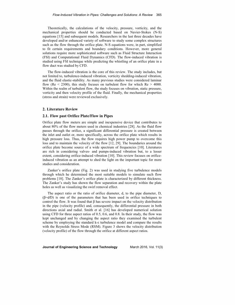
increases at constant β while �� increases with the increase in β ratio for the same
pipe diameter for all the fluids as shown in Fig. 5. The discharge coefficient
reaches its maximum values at Reynolds number between 800 and 1200, and then
slightly decreases before it becomes independent on Reynolds number of Re =
100,000 and higher. All results based on the CFD predictions were successfully
validated as they were compared with that of the literature available.
Fig. 5. Standard orifice plate discharge coefficient [33].
The structure of the flow in pipes containing orifice plate was studied and
numerically analysed by Sobey [24] who used the time dependent two-
dimensional Navier-Stokes equations. The study has shown that the flow could be
separated at sufficiently large Reynolds number. For instance, the study has
shown that there was a critical Reynolds number at which the separation could be
attained. In unsteady flow, for small Strouhal number the flow development
during acceleration occurs in a quasi-steady manner. In order to have a vortex
mixing, the peak Reynolds number must be sufficient to cause an equivalent
steady flow to separate. In a related study, Dennis and Dunwoody [34] presented
a solution to the flow up to five term truncation to approximate the solution for
laminar steady. Parameters such as drag coefficient, pressure coefficient, standing
eddy, length and stream lines patterns were compared with other experimental
and numerical solutions.
One of the features of the flow in pipes with orifice is the velocity profile of
the flow passed an orifice. The mechanism of decaying velocity (or the velocity
profile) in the laminar and turbulent flow was studied extensively by Uberoi
[14]. The study shows that the mechanism depends on estimating the swirl and
their corresponding trailing. The most important results of this study were
focused on the creation of the radial convection as a result of increasing
differences between the core trailing vortex and the velocity in the surrounding
region. The analytical analysis has shown clearly the disturbance in the flow
pattern passed the orifice plate.
It is well-known that all fittings distort the flow velocity. The size (impact) of
distortion depends on many factors such as the geometrical shape of the orifice,
viscosity, the material the fittings are made of, and whether the expansion
Flow-Induced Vibration in Pipes: Challenges and Solutions: A Review 369
Journal of Engineering Science and Technology March 2016, Vol. 11(3)
(contraction) is sudden or slow. Cherdron et al. [35] studied the effect of the
sudden expansion on the flow pattern by direct visualization using laser Doppler
anemometry. In a 2-D flow, the study examined a very accurate and detailed
description to the velocity profile. The shear layer, the study has shown, is the
main causes of the disturbances in unequal regions of flow recirculation. In
parallel study, Durst [13] studied the flow structure near the sudden contraction in
order to examine pressure losses in that region.
The 3-D studies were also conducted in order to get better insight of the
dynamics behaviour of the flow. As a typical example of these studies, Shintaro
and Masaki [36] who have shown the dynamics of a hanging tube with different
lengths carrying fluid. The experimental structure enabled them to study the static
buckling of the system.
Finally, the 3-D flow of unsteady viscous flow was examined by Mateeseu et
al. [37]. It was shown that central portion of the outer cylinder executes transverse
transitional oscillations in the longitudinal plane. The azimuthal Fourier
expansion was presented for numerical solution to solve the time dependent
incompressible Navier-stokes equations.
2.2. Vibration in Pipes
This part of the review focuses on orifice-induced vibration. As the flow passes
through the orifice, a differential pressure across the orifice and swirling take
place. The vibration caused by differential pressure and swirling could reach one
of the modes of the natural frequency of the structure which, in turn, results in
severe damage to the fittings and the wall of the pipe. In this study, the fluid is
flowing inside a pipe and the orifice plate could be treated as a contraction device
or an additive fitting. The existence of this device causes severe disturbance to the
flow regardless whether the flow is laminar or turbulent; steady or un-steady;
forced or natural, and, for all these cases, there will be always flow-induced
vibration. For small vibrations effect, there is possibility or chance of damage to
the pipe-orifice structure. The vibration could be very high and as normal mode of
flow-induced vibration reaches the normal mode of the pipe-orifice structure, the
damage becomes eminent. Studying this induced vibration is the subject of
enormous studies during the last seven decades. This section of the review
discusses the nature of each vibration and the analysis pertaining to it. The focus
in this review will be on steady-state vibration and dynamic transient vibration.
The second part is discussing the stability of the flow-induced vibrating systems.
2.3. Steady-State Vibration
The steady-state pipe vibration occurs for a long period of time. The main cause
for this vibration is the differential pressure (pressure loss) which occurs across
the orifice plate and causes, in turn, a force on the orifice plate [12, 38, 41]. Other
possible reason for this vibration is cavitation or flashing which is very normal
occurrence in the pressure-reducing valves [6]. The material fatigue is one
possible outcome of the steady-state vibration. The fatigue which is linked to the
stress could cause failure to the entire or specific parts of the structure [39].

370 M. Siba et al.
Journal of Engineering Science and Technology March 2016, Vol. 11(3)
2.4. Dynamic transient vibration
Unlike the steady state vibration, the dynamic transient vibration can occur for
relatively short time by a pulsating system causing huge force across the orifice
plate which makes this vibration more dangerous and more dramatic [37]. The
occurrence of the dynamic transient vibration is not limited to the pulsating system
only, but also to a sudden opening or closing the gate valves or the safety valves.
The existing of a turbine in the piping circuit could be another reason for dynamic
transient vibration especially at certain time during starting or ending the turbine
[39]. The dynamic transient vibration is related to changes in the flow velocity
which is subjected to both the fluid viscosity and the geometrical setting of the
piping circuit which includes the number of fittings, bending in the pipes, fast
closing valves, fast safety/relief valves, and the sudden expansion or sudden
contraction [17, 47].
2.5. Stability versus vibration in pipes
Studying the stability and vibration of pipes conveying fluid is relatively new in
the field of structural dynamics. Serious effort was intensively concerning this
topic started in 1950 when Ashley and Haviland [1] studied the vibration of
Trans.-Arabian followed by a similar study by Housner [26]. The recent study by
Olson [17] shed the light on analysing the pipe vibration. The previous studies
were performed experimentally and theoretically aiming to generate a semi-
empirical solution to the effects of the vibration on the construction. The findings
suggest that the natural frequency (resonance) decreases as the fluid velocity
increases. The physical conditions of the pipe such as the size of the pipe, the
force at the supports, the distance between the supports, the materials the pipe
made of are related to the natural frequency.
Mao et al. [10] presented a theoretical approach to the hydraulic test for the
orifice induced pressure fluctuation (PSD) and vibration in pipeline. In this study
[10], the vibration was studied with the aid of fluctuating pressure and the
acceleration due to the structure of piping circuit. The natural frequency of the
whole structure was statistically evaluated based on the fluctuating pressure and
the acceleration. The study has shown how the orifice, as an additional fitting,
disturbs the pipe flow which results in increasing the fluctuating pressure. At this
level of fluctuating pressure-induced vibration, all other factors causing the
vibration have become secondary in their effect leaving the fluctuating pressure as
the main source of vibration. Numerically, Mao et al. [10] have shown that the
location of the highest fluctuating pressure is beyond the orifice at 1.7 orifice
diameter in the axial direction. The velocity and pressure distribution (profile) are
shown in Figs. 6(a) and (b) respectively.
The pressure and pressure drop across the orifice plate were extensively
investigated by researchers. Smith et al. [16] has investigated the effect of
temperature on pressure (Fig. 7) while Wang, et al. [49] have numerical analysis
show the variation of the flow discharge and the pressure, Figs. 8(a) and (b).

Flow-Induced Vibration in Pipes: Challenges and Solutions: A Review 371
Journal of Engineering Science and Technology March 2016, Vol. 11(3)
Fig. 6. The flow velocity (a) and pressure (b) along the axis of the tube [48].
Fig. 7. Comparison between measurements and predicted profiles
with different numerical schemes by k-� turbulence model [16].

372 M. Siba et al.
Journal of Engineering Science and Technology March 2016, Vol. 11(3)
Fig. 8. The variation of flow rate with pressure at several aspect ratios
(a) and variation of flow rate with pressure drop coefficient [49].
Later Mao and Zhang [38] published their findings comparing the experimental
data to a numerical mathematical model through which the natural frequencies and
the strain response of the structure were considered. The numerical model is based
on dividing the vibration into three categories: turbulence induced vibration,
vorticity shedding induced vibration, and the fluid elastic instability.
The numerical modelling has been expanding by Matthew [39] who utilized
the Fluid-Structure Interaction (FSI) model to clarify the effect of the physical
characteristics of turbulent flow and the pipe wall vibration. The FSI software
used by Mathew [39] in this analysis was the commercial FSI software packages
which is based on Reynolds Averaged Navier-Stokes (RANS) and another model
known as the Large Eddy Simulation (LES).
Flow-Induced Vibration in Pipes: Challenges and Solutions: A Review 373
Journal of Engineering Science and Technology March 2016, Vol. 11(3)
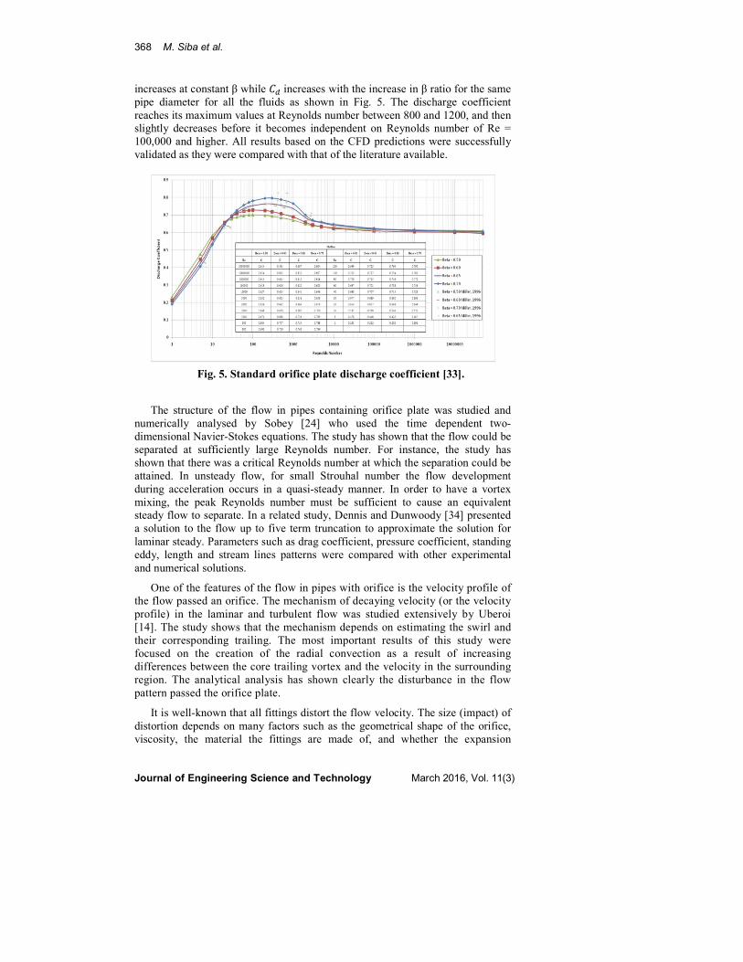
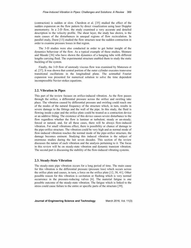
The accuracy of numerical modelling was tested by Shah et al. [50]. The peak
of the centreline velocity, Fig. 9(a) has shifted to the right as the number of cells
used in analysis increased. The effect of the increasing number of cells has shown
that the pressure decreased by about 10%, Fig. 9(b).
(a)
Fig. 9. Effect of grid size on (a) centreline axial velocity and
(b) centreline pressure profile with (1) 321,360 cells, (2) 1047,360 cells [50].
The two important factors (velocity and pressure) in the analysis of the flow
through an orifice plate were investigated by Smith et al. [16]. In this analysis
was examined for accuracy by comparing to experimental work. The analysis
has shown that there is a slight disagreement between the experimental work
and the CFD simulation analysis. The result of Smith et al. [16] and more recent
study by Shah et al. [50] suggest the need for more work in both directions:
experimental and numerical.
(b)

374 M. Siba et al.
Journal of Engineering Science and Technology March 2016, Vol. 11(3)
Fig. 10. Dimensionless (a) centreline axial velocity and (b) wall pressure
profile for air at Reynolds number of 18,400, CFD simulation (―),
experimental data of Nail (○) [16].
The controlling of the resonance frequency of a system was studied by Yakut
and Canbazoslu [40] who employed attenuators such as volume addition, compliant
boundaries, and vortex generators. It is shown that the volume addition changes the
resonance frequency and reduces the amplitudes of the pressure fluctuations. The
resonance frequency has also shown changes when the compliant boundaries are
made from plastics material. Regarding the vortex generators, it has shown that the
manganese based alloy causes reduction in the resonance frequency.
A study carried out by Bagchi, et al. [41] has shown multiple effects of the
vibrating systems. The study, experimental in nature, has tested the effect of the
pipe oscillation on wall pressure. It is shown that there is a correlation between
frequencies of pressure oscillations in a non-oscillating pipe and the natural
frequencies of the structure. This result suggests that there is an influence of
structural properties on the flow scheme in fluid dynamics. The wall pressure is
subjected to both temporal and spatial oscillation if the pipe is forced to oscillate
periodically. The calculation of the mean pressure is affected by the type of
periodic oscillation. The study has shown analytically that about 7% variation for
forced oscillating pipes.
In a recent study, Song et al. [42] carried out a laboratory implantation tests on
vortex-induced vibration (VIV) in which the riser model has an external diameter
of 16 mm and a total length of 28.0 m. The experiment was carried out for
turbulent flow (4000 < Re < 10000). To measure the dynamic response in cross-
flow and in-line directions, fibre optic grating strain gages were used and the
results have shown that the number of modes in in-line direction is doubled from
6 to 12.
Long [43] was the first who studied the problem of vibration and stability of
cantilever pipe as well as simply supported pipe. The solution indicated a slight
decrease in frequency and no decaying vibration with an increase in flow rate that
can be attributed to the flowing fluid for simply supported, fixed, and fixed-
simple ends. The theory neglects internal damping of the tube and support
damping the effect of the fluid pressure was not included before Heinrich [27]
who was the first to show its effect on the vibration. Stein and Tobriner [43]
derived the equation of flow motion in a pipe with the effect of fluid pressure
being included. They studied the dynamical behaviour of a simply-simply,
clamped-clamped, and infinitely long pipe [44].

Flow-Induced Vibration in Pipes: Challenges and Solutions: A Review 375
Journal of Engineering Science and Technology March 2016, Vol. 11(3)
The vibration-induced internal flow of entirely supported pipe was examined
by Faal et al. [45]. In their analysis, a finite length pipe with clamped ends was
analysed by Euler-Bernoulli model which is also adopted in engineering
mechanics. The equation was solved to determine both transverse and axial
displacement. The goal for this study is to determine the natural frequency of
coupled pipe-fluid system. The study was extended to evaluate the effects of the
stiffness of elastic foundation and the velocity and density of inner fluid.
The dynamic behaviour of the flow through an orifice was extensively studied
by Kim [46]. In this study, Kim has utilized the irreversible energy loss which is
related to pressure loss for turbulent jet flow. Kim proposed two different models
to evaluate the pressure difference by instantaneous inertia model and the
frequency-dependent model.
The effect of harmonic fluctuation of the fluid flow was studied by Chen [47]
who presented a study of a simply supported tube containing pulsating flow. The
equation of motion was first derived to incorporate the unsteady flow. By
employing a mathematical method known as Galerkin's method in which a
continuous operator problem is converted to a discrete problem, the equation of
motion was reduced to a system of coupled equations with multi-harmonic
coefficients. Beam and shell theories were used to investigate the vibration and
stability of pipes [51]. The effects of the fluid properties and pipe geometry and
properties on the vibration and stability in-plane and curved pipes with different
end conditions were subjected to numerous studies, for instance, [52-54].
Beside the experimental evaluation and simulation studies, there is a study
conducted by Hellum, et al. [55] to determine the empirical parameters by the
numerical analysis. The study considered a system consists of cantilever pipes
conveying fluid. The goal of this study was to determine the best parameters for
stability of the structure.
Investigating unsteady hydraulic characteristics in a short-elbow piping,
Yamanoa et al. [56] tested a methodology for one of Japanese reactors. The
methodology in this study was experimented and the results were simulated. The
results suggest that the pressure fluctuations (not the differential pressure) have
less significant effect on the flow-induced vibration and the flow separation
region was slightly influenced by the swirl inflow.
In 2008, the forces of the vibration excitation were correlated to the dynamic
forces in a study conducted by Zhang et al. [57]. The two forces (excitation and
dynamic) have different nature; the excitation forces are developed through the
fluid and could be considered as internal forces while the dynamic forces are
those forces caused by the differential pressure. Zhang et al. [57] developed semi-
analytical models for correlating the two forces resulting in better understanding
to the nature of excitation forces.
The three following tables summarize the categories through which the flow
in a pipe containing an orifice plate. Table 1 shows typical experimental designs
and procedures. Table 2 shows the numerical analyses while Table 3 shows the
simulation procedures that were used by researchers.

376 M. Siba et al.
Journal of Engineering Science and Technology March 2016, Vol. 11(3)
Table 1. Experimental: Designs and procedures.
Ref # Year Topic, area,
and interest
Investigated
Parameter Main Result
Applications of
their work
8 2011 Investigation
on fluid flow
characteristics
of the orifice
in nuclear
power plant.
�����
�
Re
Investigating flow
near orifice plate
by using a
commercial
computational
fluid dynamics
code
characteristics,
and compared
with experimental.
Used flow
measurement
technique in
industrial
application
including
nuclear fields
such as
pharmaceutical
plants.
10 2006 Experimental
studies of
orifice
induced wall
pressure
fluctuation
and pipe
vibration
Flow rate
=15, 25, 40
m3/h.
�= 0.25,
0.30,0.335
Study orifice
induced random
wall pressure
fluctuation and
vibration in a
pipeline.
Engineering pipes
conveying fluid
often suffer from
flow induced
vibration and
structural
failures& nuclear
power plant.
11 2009 Effect of
orifice shape
in synthetic jet
impingement
cooling
�= 3-25 m/s
����� =50
mm
� ������ =25
mm
Experiments are
carried out on the
effects of velocity
and orifice
spacing on the
frequency of
sound generated
by flow in a
pipeline
containing two
closely spaced
sharp-edged
orifice plates.
Orifice plates are
widely used as
convenient
pressure-reduction
and flow-
regulation devices
in a pipe flow.
41 2009 Experimental
study of the
decay pressure
fluctuations
and flow
perturbations
in air flow
through
vibrating
pipes
����� =
100mm,
�=10m.
Air flow
Re = 3 -
11*104.
Concerned with a
preliminary study
of the decay of
swirling turbulent
pipe flow and
effect on the
accuracy of orifice
plate flow meter.
The Algerian
petroleum natural
gas company

Flow-Induced Vibration in Pipes: Challenges and Solutions: A Review 377
Journal of Engineering Science and Technology March 2016, Vol. 11(3)
Table 2. Numerical analysis.
Table 3. Simulation Procedures
Ref # Year Topic, area, and
interest
Investigated
Parameter Main Result Applications of their work
15 1970 Numerical solutions
for steady past a
circular cylinder at
Reynold number up
to 100.
Re Steady-state and transient
heat transfer in a rectangular
duct with an orifice filled
with He II was investigated
both experimentally and
numerically.
Consider cooling of
magnets, it is important to
clarify heat flow in a duct
with a complicated orifice
like so as to resolve the
instability of the magnets
16 2008 Numerical
investigation of
turbulent flow
through a circular
orifice.
�= 0.5, 0.6,
0.8
Re = 18400
� = 25.4 mm
� = 9 �
� = 3.2 mm
�0 =
12.7 mm
Study the influence of
turbulence model on the
predicted results, the standard
k-ε turbulence model was
employed to compare with
the Reynolds Stress
Model (RSM).
Natural gas industry
27 2009 Orifice plate meter
wet gas flow
performance
ratio density
mass of water
mass of gas
Research into the wet gas
response of the horizontally
installed orifice plate meter is
discussed
Used to measure wet gas
flows.

378 M. Siba et al.
Journal of Engineering Science and Technology March 2016, Vol. 11(3)
3. Conclusions
Investigating the flow emerging from or within the orifice has become
increasingly important due to many industrial and experimental applications. The
main purpose of these investigations is to create very accurate measurement
procedure for the discharge of the flow in pipes for economic and safety reasons.
The current review shows the chronical historical developments for orifice
techniques which include the geometry and the shape of the orifice plate,
experimental works, and analysis during the last six decades. The following
points could be drawn from this review.
• Fabricating of orifice plate has been developing from a single shape to about
ten different shapes.
• There are about five theoretical models were developed and utilized in order
to validate or simulate the experimental work.
• Disagreement between experimental results and their relevant theoretical
models and simulations has always been expected.
• For same theoretical model, changing parameters such as the mesh number or
achieving the convergence level could result in an error of about 10%.
• The need for reducing or compiling models is necessary in reducing the
arising complexity of this topic.
Ref # Year Topic, area,
and interest
Investigated
Parameters Main Results
Applications
of their work
18 2009 CFD analysis
of
incompressible
turbulent
swirling flow
through Zanker
plate
�=1.8, 0.02
m/s, 4.1,
10.85 m/s
Thickness =
0.1D, 17D
mm.
The effects of Zanker plate
thickness and Re on the
flow characteristics have
been investigated
Flow measurement is
essential in almost all
industrial
applications: food
industry to
petrochemical, and
oil/gas processing,
such as
pharmaceutical plants
19 2010 CFD Analysis
on discharge
coefficient
during non-
Newtonian
flows through
orifice meter
�= 0.4 - 0.6,
Re=100 -
10000.
�, , ρ, ν,
��= 0.6.
Determine the discharge
co-efficient as a function of
Reynolds number with beta
ratios for single phase non-
Newtonian flows.
Moreover, the analysis on
discharge coefficient was
performed for different
concentration of the non-
Newtonian fluid
The flow meters used
in chemical industries
are orifice plate flow
meters.
20 2012 Simulations of
whistling and
the whistling
potentiality of
an in-duct
orifice with
line
aeroacoustics
�/� = 0.6 Demonstrates a linear
aeroacoustic simulation
methodology to predict the
whistling of an orifice plate
in a flow duct.
In many practical
applications related to
flow ducts, as for
example engine
exhaust systems and
ventilation systems

Flow-Induced Vibration in Pipes: Challenges and Solutions: A Review 379
Journal of Engineering Science and Technology March 2016, Vol. 11(3)
• Improving the numerical statistical methods could represent an important step
for reducing the confusion arises from complexity of the boundary conditions.
• It was found that previous studies were focusing on aspect ratios started
sequentially incremented at 0.1 from the minimum value of 0.2 to mostly 0.7
while no studies have shown studies with increment different from 0.1.
• Some studies have shown dramatic change of follow vorticities and swirling
activities as the aspect ratio increased from 0.2 to 0.3 and as such more
studies are needed to cover the behaviour between these two aspect ratios.
• Studies are not unified regarding the principal frequency modes and their
relevant second harmonic frequencies.
• The need for enhancing software is very important step.
References
1. Ashley, H. and Haviland, G. (1950). Bending vibrations of a pipe line
containing flowing fluid. Journal of Applied Mechanics, 17, 229-132.
2. Nail, G.H. (1991). A Study of 3-Dimensional flow through orifice meter.
PhD Dissertation, Texas A&M University.
3. Mao, Q.; Zhang, J; Yushan, L.; Duan, Q.; and Wang, H. (2003). High-level
vibration and noise analysis of nuclear pipes with orifice. Transactions of
the 17th International Conference SMiRT 17, Prague, Czech Republic,
August 17–22.
4. Wach, J.C. (1990). Piping vibration analysis. Proceedings of the nineteenth
turbomachinery Symposium. Texas A&M University, Texas 77840-3123.
5. Olson, D.E. (1985). Piping vibration experience in power plant. Pressure
Vessel and Piping Technology. ASME Book No.H00330.
6. U. S. NRC. (1998). Cavitation erosion of letdown line orifices resulting in
fatigue cracking of pipe welds. Information Notice No. 98–45.
7. Website of Kansai Electric Power Co-Mihama Power Station. (2001).
Outline of incidents and failures occurred at NPPS in FY. Retrieved July 5,
2012 from Wikipedia.org/wiki/Kansai_Electric_Power_Company.
8. Garrison, W.G (1988). Major fire and Explosion analyzed for 30-years period
Hydrocarbon processing. Hydrocarbon Processing, September, 115-120.
9. Abou El-Azm. A.; Chong. A.; Nicolleau, F.; and Beck, S. (2010). Experimental
study of the pressure drop after fractal-shaped orifices turbulent pipe flows.
Experimental Thermal and Fluid Science, 34 (J), 104-111.
10. Mao, Q.; Zhang, J; Yushan, L.; Duan, Q.; and Wang, H. (2006).
Experimental studies of orifice-induced wall pressure fluctuations and pipe
vibration. International Journal of Pressure Vessels Piping, 83, 505–511.
11. Mangesh, C.; Bhalchandra, P.; and Amit, A. (2009). Effect of orifice shape in
synthetic jet impingement cooling. Experimental Thermal and Fluid Science,
34 (J), 246-256.
12. Fossa, M. and Guglielmini, G. (2002). Pressure drop and void fraction
profiles during horizontal flow through thin and thick orifices. Experimental
Thermal and Fluid, Science, 26, 513–523.

380 M. Siba et al.
Journal of Engineering Science and Technology March 2016, Vol. 11(3)
13. Durst, F. (1985). Investigation of laminar flow in a pipe with sudden contraction
of cross-sectional area, Journal Computers and Fluids, 13(1), 15-36.
14. Uberoi, M.S. (1979). Mechanisms of decay of laminar and turbulent vortices.
Journal Fluid Mechanics, 90(2), 241-255.
15. Dennis, S.C.R and Chang, G.Z. (1970). Numerical solutions for steady past a
circular cylinder at Reynolds number up to 100. Journal. Fluid Mechanics,
42, 471-490.
16. Smith, E.; Ridhuan, A.; Somravysin, P.; and Promvonge, P. (2008).
Numerical investigation of turbulent flow through a circular orifice. KMITL
Science Journal, 8(1), 43-50.
17. Olson, D.E. (2008). Pipe vibration testing and analysis. American Society of
Mechanical Engineers-10.11151 Chapter 37, 1-34.
18. EI Drainy, Y.A.; Sag, K.M.; Aly, H.S.; and Mohd Jaafer, M.N. (2009). CFD
analysis of incompressible turbulent swirling flow through flow through
Zanker plate, Engineering Applications of computational. Fluid Mechanics,
3(4), 562-572.
19. Arun, N. (2010). CFD analysis on discharge coefficient during Non-
Newtonian flows through orifice meter. Journal of Engineering Science and
Technology, 2(7), 3151-3164.
20. Kierkegaard, A.; Allam, S.; and Efraimsson, G. (2011). Simulation of
whistling and the whistling potentiality of an induct orifice with linear
aeroacustics. Journal of sound and vibration, 331, 1084-1096.
21. ASME B31.1-2007, Power piping, ASME Code for pressure piping, B31,
The American Society of Mechanical Engineers.
22. ISO (2003). ISO 5167 (2003). Measurement of fluid flow by means of
pressure differential devices inserted in circular cross-section conduits
running full.
23. Lab Manual, University of Jordan. (2012). The laboratory experiments for
mechanical engineering, fall (2012). Retrieved February 16, 2014, from
http://fetweb.ju.edu.jo/ME/courses/labs/measurements/labsheet/
Experiment%20No%203%20flow%20measurements.pdf
24. Sobey, I.J. (1980). On flow through furrower channels: part 1, calculated
flow patterns. Journal Fluid Mechanics, 96(1), 1-26.
25. Sobey, I.J. (1983). The occurrence of separation in oscillatory flow. Journal.
Fluid Mechanics, 134(9), 247-257.
26. Housner, G.W. (1952). Bending vibration of a pipe line containing flowing
fluid. Journal of Fluid Mechanics, 19(2), 205-208.
27. Heinrich, G. (1956). Vibration of tube with flow. Zeitschvit Fur Angewamte
Mathematick and Mechanik, 36, 417-427.
28. Richard, S. (2009). Orifice plate meter wet gas flow performance. Flow
Measurement and Instrumentation, 20(4-5), 141-151.
29. Dugdale, D.S. (1997). Viscous flow through a sharp edged orifice.
International Journal of engineering Science, 35, 725-729.
30. Siba, M.A.; Wan Mohmood, M.; Nuawi, M.Z.; Rasani, R.; and Nassir, M.
(2014) Investigation of physical properties of 3-D flow and mechanical

Flow-Induced Vibration in Pipes: Challenges and Solutions: A Review 381
Journal of Engineering Science and Technology March 2016, Vol. 11(3)
properties of the pipe for turbulent flow. The 7th International Meeting on
Advances in Thermofluids, Kuala Lumpur, Malaysia.
31. Amnache, A; Omri, M.; and Fréchette, L.G. (2010). An analytical and
numerical study of rectangular orifice plate micro-flowmeters. ASME 2010
International Mechanical Engineering Congress and Exposition, British
Columbia, Canada, November, 2010, Paper No. IMECE2010-40470, 659-665.
32. Manshoor, B. and Nicolleau, F.C.G.A.; and Beck, S.B.M. (2011). The fractal
flow conditioner for orifice plate meters. Flow measurement and
instrumentation, 22(3), 208-214.
33. Colter L. Hollingshead, (2011). Discharge coefficient performance of
Venturi, standard concentric orifice plate, V-cone, and wedge flow meters at
small Reynolds numbers. A thesis submitted in partial fulfillment of
requirements of the degree of Master of Science in Civil Engineering, Utah
University, Logan, Utah.
34. Dennis, S. C. R. and Dunwoody, J. (1966). The steady flow of a viscous fluid
a flat plate. ournal. Fluid Mechanics, 24, 577-595.
35. Cherdron, W.; Durst, F.; and Whitelaw, J.H. (1978). Asymmetric low and
instabilities in symmetric ducts with sudden expansions. Journal Fluid
Mechanics, 84 (1), 13-31.
36. Shintaro, K. and Masaki, S. (2003). Stability and bifurcation of tube
conveying flow. Journal of Physical Society of Japan, 72, 3106-3112.
37. Mateescu, D.; Paidoussis, M.P.; and Belage, F. (1994). Unsteady annular
viscous flow between oscillating cylinder. Part II: A hybrid time integration
solution based on azimuthal Fourier expansions for configurations with
annular backsteps, Journal Fluid and structures, 8(5), 509-527.
38. Mao, Q.; and Zhang, J. (2007). Orifice-induced wall pressure fluctuations
and pipe vibrations: Theory and modeling fluid excitations, Flow Turbulence
Combust, 79, 25-40.
39. Matthew, T.P. (2003). Large eddy simulation based turbulent flow induced
vibration of fully developed pipe flow, A M.Sc. thesis submitted to the
faculty of Brigham Young University.
40. Yakut, K.; and Canbazoslu, S. (1998). Toward attenuation of self-sustained
oscillations of a turbulent jet through two orifices with same diameter.
Journal of engineering and environmental sciences, 22, 17-26.
41. Bagchi, K.; Gupta, S. K.; Kushari, A.; and Iyengar, N. G. R. (2009).
Experimental study of pressure fluctuations and flow Perturbations in air flow
through vibrating pipes. Journal of sound and vibration, 328(4-5), 441-455.
42. Song, J.; Lu, L.; Teng, B.; Park, H.; Tang, G.; and Wu, H. (2011). Laboratory
tests of vortex induced vibrations of along flexible riser pipe subjected to
uniform flow. Ocean Engineering 38(11-12), 1308-1322.
43. Long, R.H. (1955). Experimental and theoretical study of transverse
vibration of a tube containing flow fluid. Journal Applied Mechanics,
22, 65-68.
44. Stein, R.A. and Tobriner, M. W. (1970). Vibration of piping containing flow
fluids. Journal of Applied Mechanics, 37(4), 906-916.

382 M. Siba et al.
Journal of Engineering Science and Technology March 2016, Vol. 11(3)
45. Faal, R.T. (2009). Flow-induced vibration of pipeline on elastic support.
Procedia Engineering, 14, 2986-2993.
46. Kim, I.Y. (2008). Advanced numerical experimental transient modeling of
water and gas pipeline flows incorporating distributed and local effects,
Thesis for Doctor Philosophy, School of Civil Engineering and Mining
Engineering, The University of Adelaide Australia.
47. Chen, S.-S. (1971). Dynamic stability of tube conveying fluid. Journal of the
Engineering Mechanics, 97(5), 1469-1485.
48. Ahuja, V.; Hosangadi, A.; Hitt, M.A.; and Lineberry, M. (2013). Numerical
simulation of instabilities in single-hole orifice elements, 49th
AIII/ASME/SAE/ASEE Joint propulsion conference and exhibit, 14-17 July,
San Jose, California, USA.
49. Haimin, W; Shujuan, X.; Qingyi, S.; Caimin, Z.; Hao, L.; and Eryun, C.
(2013). Experiment study on pressure drop of multistage letdown orifice
tube, Nuclear Engineering and Design, 265, 633-638.
50. Shah, M.; Joshi, J.B.; Kalsi, A.S.; Prasad, C.S.R.; and Shukla, D.S. (2012).
Analysis of flow through an orifice meter: CFD simulation, Chemical
Engineering Science, 71, 300-309.
51. Paidoussis, M.P. and Deaisc, J.B. 1972. Flutter of cylindrical shells
conveying fluid, Journal Sound and Vibration, 20, 9-16.
52. Chen, S.-S. (1972). Vibration and stability of a uniformly curved tube
conveying. Journal of Acoustic. Society of America, 51, 223-232.
53. Chen, S.-S. (1973) Out-of plane vibration and stability of curved tube
conveying fluid, Journal of Applied Mechanics, 40(2), 362-368.
54. Unny, T.E.; Martin, E.L.; and Dubey, R.N. (1970). Hydroclastic instability of
uniformly curved pipe fluid system. Journal Applied Mechanics, 37(3), 817-822.
55. Hellum, A.M.; Mukherjee, R.; and Hull, A.J. (2010). Dynamics of pipe
conveying fluid with non-uniform turbulent and laminar velocity profiles.
Journal of Fluid and structure, 26(5), 804-813.
56. Yamano, H.; Tanaka, M.;Kimura, N.; Ohshima, H.; Kamide, H.; and Watabe,
O. (2011). Development of flow-induced vibration evaluation methodology
for large-diameter piping with elbow in Japan sodium-cooled fast reactor.
Journal of Nuclear Engineering and Design, 241 (11), 4464- 4475.
57. Zhang, C.; Mureithi, N.W.; and Pettigrew, M.J. (2008). Development of
models correlating vibration excitation forces to dynamic characteristics of
two-phase flow in a tube bundle. International Journal of Multiphase Flow.
34(11), 1048-1057.