Embed Size (px)
Citation preview
May 22, 2010 1:40 WSPC - Proceedings Trim Size: 9in x 6in Cai˙Clawar
1
Experimental Evaluation of a GoniometerFor the Identification of Anatomical Joint Motions
V. A. D. CAI∗ , B. BRU, P. BIDAUD,
V. HAYWARD and V. PASQUI
Institut des Systemes Intelligents et de Robotique, Universite Pierre et Marie Curie,
Paris, 75005, France∗E-mail: cai,bru,bidaud,hayward,[email protected]
www.isir.upmc.fr
F. GOSSELIN
CEA, LIST, Laboratoire de Robotique Interactive, Fontenay Aux Roses, 92265, FranceE-mail: [email protected]
This paper exposes the experimental evaluation of a new technique for the
estimation of the instantaneous helical axis of movement of human anatomi-
cal joints. The measurement technique, using a six degrees of freedom spatialelectro-goniometer, is tested onto a simple revolute joint and onto a subject’s
knee. A motion capture system with active optical markers is used at the same
time in order to validate the measurement results.
Keywords: Instantaneous Screw Axis (ISA), Knee Joint Motion.
1. Motivation
The notion of screw motion (Chasle’s theorem, 1830), which relates to thedescription of the instantaneous motion of a body in space in terms of asimultaneous translation and rotation around a single axis, is particularlyuseful concept in biomechanics since anatomical joints never behave liketrue lower pairs, but invariably undergo composite motions through theirrange. Hence, there has long been an interest in the determination of theinstantaneous screw axis of the relative motion between two segments ofa limb.5 In the knee, for instance, general six degree-of-freedom spatialmotions must be considered.
The International Society of Biomechanics (ISB) recommends the useof the Helical Axis (HA) method.9 Various studies are aimed at evaluatingthe reliability of the estimation of the instantaneous screw axis (ISA) based
Proceedings of the Thirteenth International Conference on Climbing and Walking Robots and the Support Technologies for Mobile Machines, CLAWAR 2010, in press.
May 22, 2010 1:40 WSPC - Proceedings Trim Size: 9in x 6in Cai˙Clawar
2
on measurement acquired from anatomical limbs.3,6,8 It is found a commonproblem is a lack of reliability of the estimate at low angular velocities andrestrictive assumptions as to the nature of the motion.
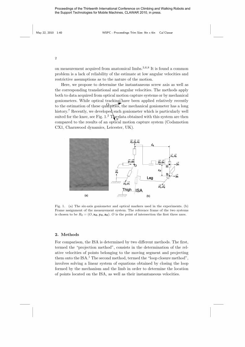
Here, we propose to determine the instantaneous screw axis as well asthe corresponding translational and angular velocities. The methods applyboth to data acquired from optical motion capture systems or by mechanicalgoniometers. While optical tracking have been applied relatively recentlyto the estimation of these quantities, the mechanical goniometer has a longhistory.7 Recently, we developed such goniometer which is particularly wellsuited for the knee, see Fig. 1.2 The data obtained with this system are thencompared to the results of an optical motion capture system (CodamotionCX1, Charnwood dynamics, Leicester, UK).
ISAThigh
Leg
(a) (b)
Fig. 1. (a) The six-axis goniometer and optical markers used in the experiments. (b)
Frame assignment of the measurement system. The reference frame of the two systemsis chosen to be R0 = (O,x0,y0, z0). O is the point of intersection the first three axes.
2. Methods
For comparison, the ISA is determined by two different methods. The first,termed the “projection method”, consists in the determination of the rel-ative velocities of points belonging to the moving segment and projectingthem onto the ISA.1 The second method, termed the “loop closure method”,involves solving a linear system of equations obtained by closing the loopformed by the mechanism and the limb in order to determine the locationof points located on the ISA, as well as their instantaneous velocities.
Proceedings of the Thirteenth International Conference on Climbing and Walking Robots and the Support Technologies for Mobile Machines, CLAWAR 2010, in press.
May 22, 2010 1:40 WSPC - Proceedings Trim Size: 9in x 6in Cai˙Clawar
3
2.1. Projection Method
The localization of the ISA is obtained from the computation of the orthog-onal projections, A′i, of points Ai attached to the moving segment onto theISA. These projections are:
AiA′i = (vAi
∧w)/(|w|2), (1)
where w and vAi are the angular and the translational velocities of thesecond segment at the point Ai. The relative translational velocity of thetwo body segments, which is also the instantaneous translational velocityof the anatomical joint can be estimated as follows:
vA′i
= vAi−w ∧AiA
′i (2)
2.2. Loop Closure Method
By considering the subject’s second limb and the anatomical joint as partsof the linkage, the loop-closure equation may be written
JP (q)q −(
w06
vP
)= 0, (3)
where q is the vector of joint angles. JP (q) is the Jacobian matrix writ-ten at a point, P , located on the ISA. The quantities (w06, vP )> =(ωx, ωy, ωz, vx, vy, vz)> are components of the twist at P . The coordinatesof the point P and the values of (w06, vP )> can be determined by solvingthe system of equations (3).
These two methods can be used when using a mechanical goniometer,whereas only the first is applicable to data from optical trackers.
3. Results
Our prototype goniometer has precision potentiometers to measure the jointangles that have a resolution of 0.02 degrees. Two experiments were con-ducted to evaluate performances. The angular calibration error was esti-mated at 5 degrees maximum. The sensor data were recorded at 1 kHz.
The motion capture system was used to measure the joint movements.The location data of the markers were recorded at 200 Hz. The standarddeviation of the position measurements of a static marker is 0.05 mm at3 m on the X and Z axes and 0.3 mm on the Y axis.
In biomechanics applications markers are attached to the skin. Muscularcontractions produce skin movements that introduce measurements errors
Proceedings of the Thirteenth International Conference on Climbing and Walking Robots and the Support Technologies for Mobile Machines, CLAWAR 2010, in press.
May 22, 2010 1:40 WSPC - Proceedings Trim Size: 9in x 6in Cai˙Clawar
4
that are difficult to quantify. In an effort to reduce this effect, a least-squareoptimisation method — that enforced the constraint of constant distancebetween markers — was applied on the raw kinematic data of the five activemarkers of each body segment.
3.1. Test on a revolute joint
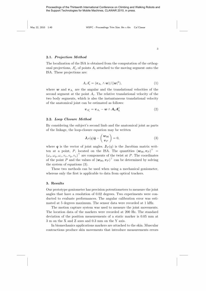
The goniometer was fixed onto a revolute joint which was supposed to beperfect (see Fig. 2). The joint was moved at different speeds between 0 and80 degrees.
Fig. 2. The electro-goniomter and optical
markers fixed onto a simple revolute joint.
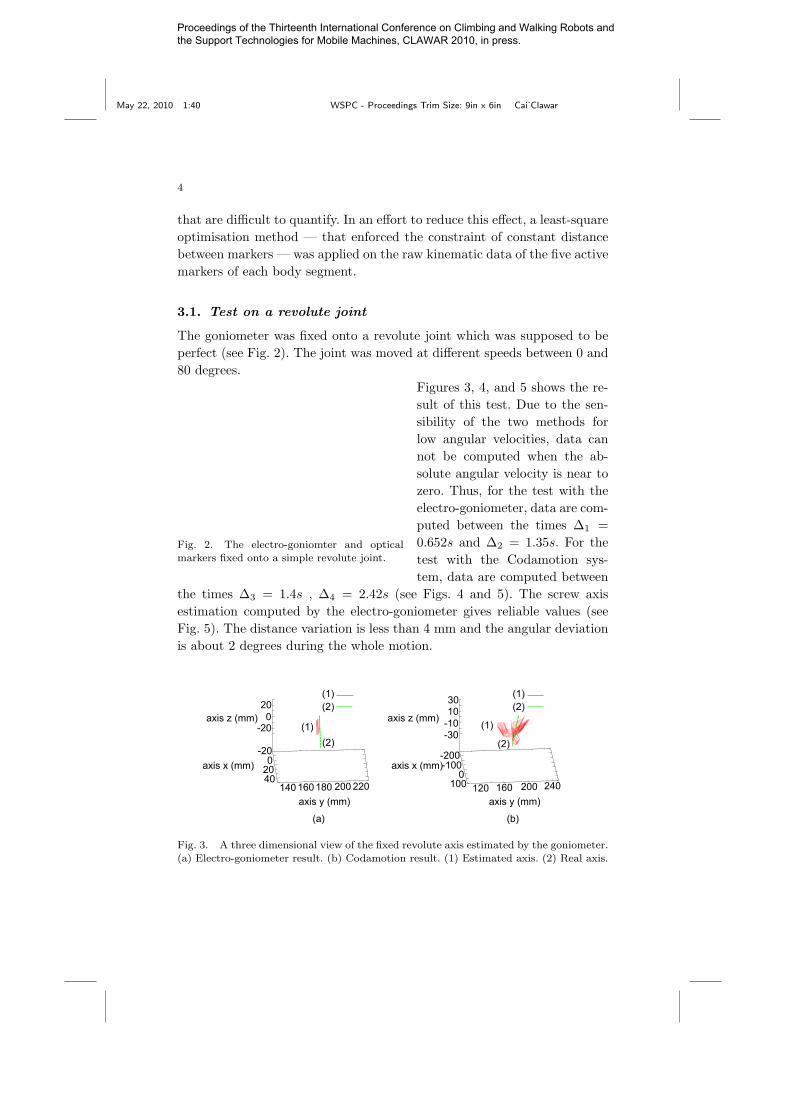
Figures 3, 4, and 5 shows the re-sult of this test. Due to the sen-sibility of the two methods forlow angular velocities, data cannot be computed when the ab-solute angular velocity is near tozero. Thus, for the test with theelectro-goniometer, data are com-puted between the times ∆1 =0.652s and ∆2 = 1.35s. For thetest with the Codamotion sys-tem, data are computed between
the times ∆3 = 1.4s , ∆4 = 2.42s (see Figs. 4 and 5). The screw axisestimation computed by the electro-goniometer gives reliable values (seeFig. 5). The distance variation is less than 4 mm and the angular deviationis about 2 degrees during the whole motion.
-200
2040
140 160180 200 220
-200
20
-200-100
0100 120 160 200 240
-30-101030
axis z (mm)
axis x (mm)
axis y (mm)
axis z (mm)
axis x (mm)
axis y (mm)
(1)(2)
(1)(2)
(1)(2)
(1)
(2)
(a) (b)
Fig. 3. A three dimensional view of the fixed revolute axis estimated by the goniometer.
(a) Electro-goniometer result. (b) Codamotion result. (1) Estimated axis. (2) Real axis.
Proceedings of the Thirteenth International Conference on Climbing and Walking Robots and the Support Technologies for Mobile Machines, CLAWAR 2010, in press.
May 22, 2010 1:40 WSPC - Proceedings Trim Size: 9in x 6in Cai˙Clawar
5
-100
1020304050607080
0 0.5 1 1.5 2 2.5 3 3.5 4 4.5 5
Degree
Time (second)0 1 2 3 4 5 6 7 8 9 10
-100
102030405060708090
Degree
Time (second)
(a) (b)
(1)
(3)(2)
(1)
(3)(2)
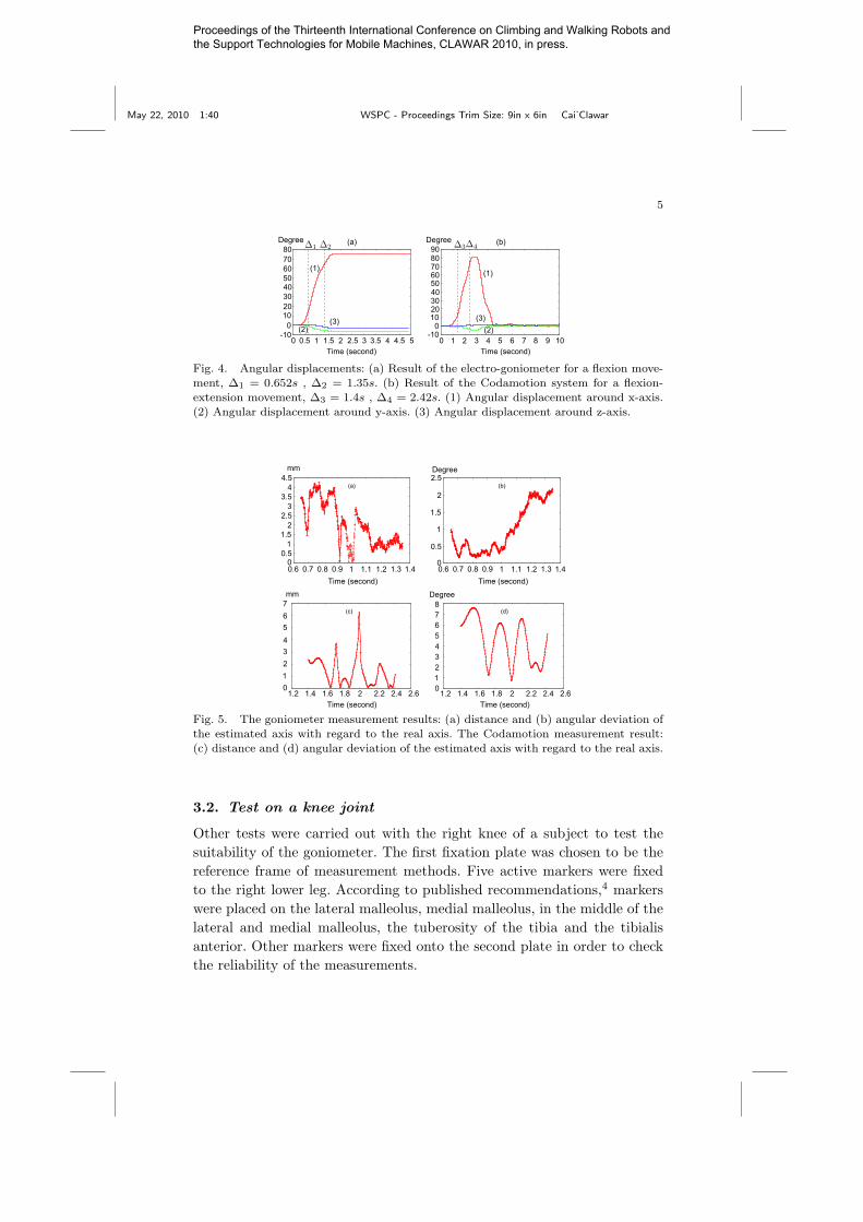
Fig. 4. Angular displacements: (a) Result of the electro-goniometer for a flexion move-ment, ∆1 = 0.652s , ∆2 = 1.35s. (b) Result of the Codamotion system for a flexion-
extension movement, ∆3 = 1.4s , ∆4 = 2.42s. (1) Angular displacement around x-axis.
(2) Angular displacement around y-axis. (3) Angular displacement around z-axis.
00.5
11.5
22.5
33.5
44.5
0.6 0.7 0.8 0.9 1 1.1 1.2 1.3 1.4
mm
Time (second)
0
0.5
1
1.5
2
2.5
0.6 0.7 0.8 0.9 1 1.1 1.2 1.3 1.4Time (second)
Degree
(a) (b)
01234567
Time (second) Time (second)
mm Degree
(c) (d)
012345678
1.2 1.4 1.6 1.8 2 2.2 2.4 2.61.2 1.4 1.6 1.8 2 2.2 2.4 2.6
Fig. 5. The goniometer measurement results: (a) distance and (b) angular deviation of
the estimated axis with regard to the real axis. The Codamotion measurement result:(c) distance and (d) angular deviation of the estimated axis with regard to the real axis.
3.2. Test on a knee joint
Other tests were carried out with the right knee of a subject to test thesuitability of the goniometer. The first fixation plate was chosen to be thereference frame of measurement methods. Five active markers were fixedto the right lower leg. According to published recommendations,4 markerswere placed on the lateral malleolus, medial malleolus, in the middle of thelateral and medial malleolus, the tuberosity of the tibia and the tibialisanterior. Other markers were fixed onto the second plate in order to checkthe reliability of the measurements.
Proceedings of the Thirteenth International Conference on Climbing and Walking Robots and the Support Technologies for Mobile Machines, CLAWAR 2010, in press.
May 22, 2010 1:40 WSPC - Proceedings Trim Size: 9in x 6in Cai˙Clawar
6
-90-80-70-60-50-40-30-20-10
010
(1)
(2)
(3)
(1)
(2)
(3)
-90-80-70-60-50-40-30-20-10
010
0 0.5 1 1.5 2 2.5 3 3.5 4 4.5 50 0.5 1 1.5 2 2.5 3 3.5 4 4.5 5
Degree
Time (second) Time (second)
Degree
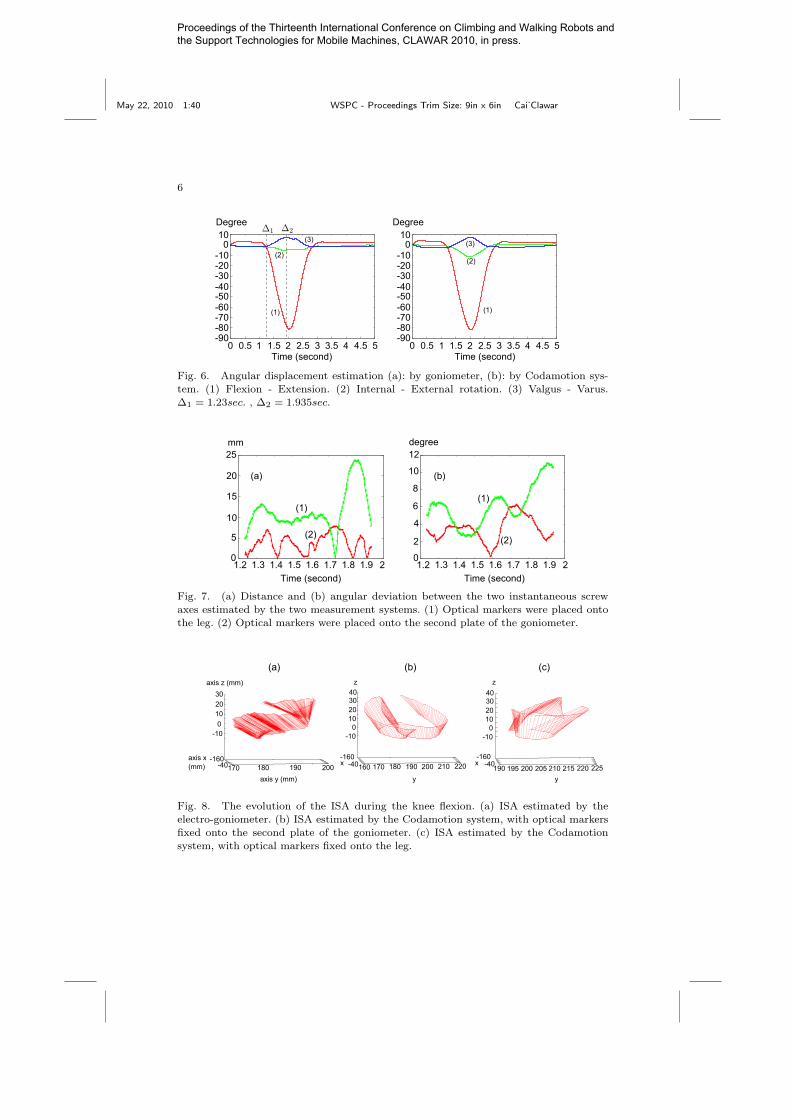
Fig. 6. Angular displacement estimation (a): by goniometer, (b): by Codamotion sys-tem. (1) Flexion - Extension. (2) Internal - External rotation. (3) Valgus - Varus.
∆1 = 1.23sec. , ∆2 = 1.935sec.
1.2 1.3 1.4 1.5 1.6 1.7 1.8 1.9 20
5
10
15
20
25
0
2
4
6
8
10
12
1.2 1.3 1.4 1.5 1.6 1.7 1.8 1.9 2
mm degree
Time (second) Time (second)
(a) (b)
(1)(1)
(2) (2)
Fig. 7. (a) Distance and (b) angular deviation between the two instantaneous screw
axes estimated by the two measurement systems. (1) Optical markers were placed ontothe leg. (2) Optical markers were placed onto the second plate of the goniometer.
-160-40170 180 190 200
-100
102030
-40-160
-40-160
axis z (mm)
160 170 180 190 200 210 220
-100
10203040
-100
10203040
190 195 200 205 210 215 220 225axis x (mm) x x
axis y (mm) y y
zz
(a) (b) (c)
Fig. 8. The evolution of the ISA during the knee flexion. (a) ISA estimated by the
electro-goniometer. (b) ISA estimated by the Codamotion system, with optical markersfixed onto the second plate of the goniometer. (c) ISA estimated by the Codamotion
system, with optical markers fixed onto the leg.
Proceedings of the Thirteenth International Conference on Climbing and Walking Robots and the Support Technologies for Mobile Machines, CLAWAR 2010, in press.
May 22, 2010 1:40 WSPC - Proceedings Trim Size: 9in x 6in Cai˙Clawar
7
3.3. Discussion
The initial tests of the goniometer on a revolute joint provided coherentresults. However, for the test on human knee, the estimated ISA and theangular values differed on the two systems, see Fig. 6 where a significantdifference between the estimated angular values can be seen. Angular esti-mation errors can reach 10 degrees. On the other hand, we can see that thedifference between the data obtained with the electro-goniometer and theCodamotion system vary when the second set of optical markers is fixed onthe second plate of the goniometer and on the leg. This supports the notionthat estimation is very sensitive to the displacement of the fixation platesand of the optical markers due to muscular contractions (see Fig. 7). Thedistance and the angular deviation between the two ISA can reach morethan 20 mm and 10 degrees.
Angular estimation errors can be reduced by a precise calibration pro-cedure, better sensors on the goniometer and by using more markers withthe optical tracking device.
Nevertheless, the most likely source of errors is the numerical differenta-tion needed to obtain velocity values. A number of approaches could be ap-plied to improve numerical stability of the estimation algorithm, especiallyat low speeds.
4. Conclusion
A new method for the estimation of human anatomical joint motions,using a multi-linkage goniometer was proposed in this paper. Simula-tions and experimental tests were carried in order to evaluate the per-formance of this measurement system. Simple tests on elementary joints,such as revolute joints, provided reliable results. Tests on the human kneejoint, showed significant differences between measurements provided by theelectro-goniometer and a motion capture system using optical markers. Infuture work, efforts will be directed at improving the reliability of the esti-mation of the ISA with the two approaches.
Proceedings of the Thirteenth International Conference on Climbing and Walking Robots and the Support Technologies for Mobile Machines, CLAWAR 2010, in press.
May 22, 2010 1:40 WSPC - Proceedings Trim Size: 9in x 6in Cai˙Clawar
8
References
1. B. Bru and V. Pasqui, A new method for determining the location of theinstantaneous axis of rotation during human movements, (Computer Methodsin Biomechanics and Medical Engineering, Vol. 12, sup. 1, pages 65–67, 2009).
2. V.A.D. Cai, P. Bidaud, V. Hayward and F. Gosselin Design of Self-AdjustingOrthoses For Rehabilitation, (Proceedings of the 14th IASTED InternationalConference Robotics and Applications (RA 2009), paper n. 664-030, pages215–223, 2009).
3. R.M. Ehrig, W.R. Taylor, G.N. Duda, and M.O. Heller, A survey of formalmethods for determining the centre of rotation of ball joints, (J Biomech 39(2006): 2798–2809).
4. S. Van Sint Jan, Color Atlas of Skeletal Landmark Definitions, (ChurchillLivingstone, Elsevier,Philadelphia, 2007).
5. G.L. Kinzel, A.S. Hall and B.M. Hillberry, Measurement of the total motionbetween two body segments - I. Analytical development, (J. Biomechanics, Vol.5, pages 93–105, 1972).
6. T. Monnet, E. Desailly, M. Begon, C. Valle, and P. Lacouture, Comparison ofthe SoRE and HA methods for locating in vivo the glenohumeral joint centre,(J Biomech 40 (2007): 3487–3492).
7. M.A. Townsend, M. Izak and R.W. Jackson, Total motion knee goniometry,(J. Biomechanics , Vol. 10, pages 183–193, 1977).
8. H.J. Woltring, R. Huiskes, A. de Lange, and F.E. Veldpaus, Finite centroidand helical axis estimation from noisy landmark measurements in the study ofhuman joint kinematics, (J Biomech, 18(5):379-389, 1985).
9. G. Wu, F.C.T. van der Helm, H.E.J. DirkJan Veeger, M. Makhsous,P. Van Roy, C. Anglin, J. Nagels, A.R. Karduna, K. McQuade, X. Wang,F.W. Werner, B. Buchholz, and International Society of Biomechanics, Isbrecommendation on definitions of joint coordinate systems of various joints forthe reporting of human joint motionpart ii: shoulder, elbow, wrist and hand,(J. Biomechanics, 38(5):981-992, 2005).
Proceedings of the Thirteenth International Conference on Climbing and Walking Robots and the Support Technologies for Mobile Machines, CLAWAR 2010, in press.