Embed Size (px)
Citation preview
CHAPTER 3: EXPERIMENTAL EQUIPMENT AND
PROCEDURES
3 EXPERIMENTAL EQUIPMENT
AND PROCEDURES
3.1 INTRODUCTION
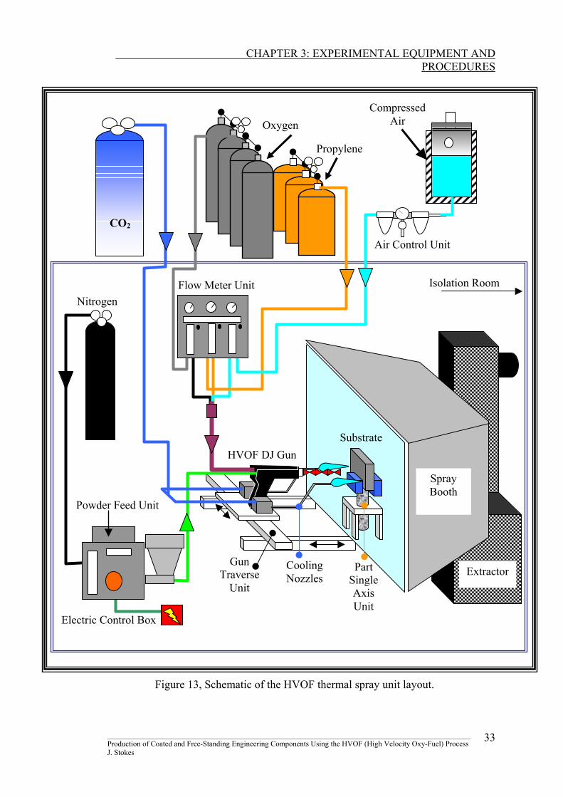
In the present research, a HVOF thermal spraying facility was used to produce
coatings and to investigate the possibility of producing free-standing engineering
components. The facility consists of three main units:
1. Spraying system
2. Support system
3. Controlling system
These systems are integrated together for the production of coatings, or thermally
spray-formed engineering components. The spraying system equipment was
supplied by Sulzer METCO, the developers of the Diamond Jet (DJ) HVOF system,
whereas the support and controlling systems were purchased from individual
companies. Figure 13 shows a schematic diagram of the layout of the complete
facility.
In addition to the process equipment used, equipment used to measure various
characteristics of the coating/forming material are also presented, along with the
procedure used to conduct these measurements.
________________________________________________________________________________________________ Production of Coated and Free-Standing Engineering Components Using the HVOF (High Velocity Oxy-Fuel) Process J. Stokes
32
CHAPTER 3: EXPERIMENTAL EQUIPMENT AND
PROCEDURES
Propylene
Compressed Air
Air Control Unit
Nitrogen Flow Meter Unit
Electric Control Box
Powder Feed Unit
HVOF DJ Gun
Cooling Nozzles Extractor
Spray Booth
Gun Traverse
Unit
Substrate
Part Single Axis Unit
Oxygen
CO2
Isolation Room
Figure 13, Schematic of the HVOF thermal spray unit layout.
________________________________________________________________________________________________ Production of Coated and Free-Standing Engineering Components Using the HVOF (High Velocity Oxy-Fuel) Process J. Stokes
33
CHAPTER 3: EXPERIMENTAL EQUIPMENT AND
PROCEDURES
3.2 HVOF THERMAL SPRAYING SYSTEM
The objective of the HVOF process is to transfer kinetic and thermal energy to
powder particles, with high efficiency. This energy is achieved by a combination of
gases to combust and propel these particles. The HVOF thermal spraying system
consists of a gas supply unit, flow meter unit, powder feed unit, and a Diamond Jet
(DJ) gun, all supplied by Sulzer METCO. Description of these units and their
working principles are presented in my additional report [34].
3.2.1 Supporting Systems
Thermal spraying equipment should be operated in a safe and workable environment.
Safety for the operator is very important, therefore proper functioning facilities must
be in place before the commencement of spraying. In addition powder materials are
very often hazardous, therefore personal safety equipment must be worn. Under the
heading of supporting systems, the following are discussed in my additional report
[34]: the spray booth and exhaust system, facility isolation, electrical power supply,
and safety equipment.
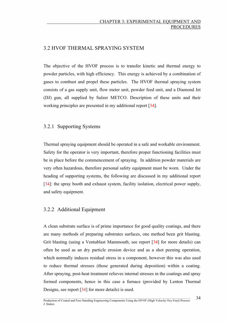
3.2.2 Additional Equipment
A clean substrate surface is of prime importance for good quality coatings, and there
are many methods of preparing substrates surfaces, one method been grit blasting.
Grit blasting (using a Ventublast Mammouth, see report [34] for more details) can
often be used as an dry particle erosion device and as a shot peening operation,
which normally induces residual stress in a component, however this was also used
to reduce thermal stresses (those generated during deposition) within a coating.
After spraying, post-heat treatment relieves internal stresses in the coatings and spray
formed components, hence in this case a furnace (provided by Lenton Thermal
Designs, see report [34] for more details) is used. ________________________________________________________________________________________________ Production of Coated and Free-Standing Engineering Components Using the HVOF (High Velocity Oxy-Fuel) Process J. Stokes
34
CHAPTER 3: EXPERIMENTAL EQUIPMENT AND
PROCEDURES
3.3 FACILITIES DEVELOPMENT
At the onset of the current research, modifications to the existing system were
required to upgrade the facility for repeatability, process control and accurate
measurement (distance, temperature and residual stress). Previously to the research
presented here, thermal spraying at the Materials Processing Research Centre was
carried out manually (the gun was hand held, hence spraying distances were
estimated), which lead to some variability in spraying distances (and in turn spraying
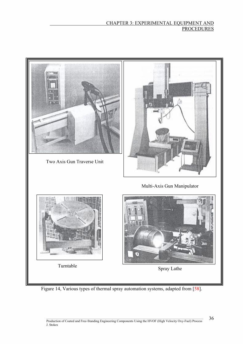
temperature). There are many thermal spray automation systems available, as shown
in figure 14. Some of these automated systems move in one or two directions
(traverse units), or in the case of multidirectional deposition, robotic systems are
used to move the gun/torch [58]. In the case of coating cylindrical components,
either a lathe or a turntable is used to move the component. In all of these cases,
traverse and rotational speeds must be calculated to yield quality coatings [59]. In
the present research, a specially designed system of controlling the spraying distance
was implemented as part of the present work, and comprises of a linear traverse unit.
In order to produce large deposit components, a part single-axis unit was designed.
In an effort to reduce residual stress, interruption to spraying was previously the only
method of controlling spraying temperature to a set value. The result was the
formation of almost distinct layers in the sprayed microstructure, which formed a
brittle coating or component. Therefore forced cooling, by the use of a carbon
dioxide cooling system, was required to constrain the spraying temperature.
Temperature was previously measured by an optical pyrometer, which proved
unsatisfactory because the measurement it recorded for spraying temperature was
affected by the flame of the spray gun. Thus a system incorporating thermocouples
was utilised in the present work. Each of these system developments are described
in the following sections.
________________________________________________________________________________________________ Production of Coated and Free-Standing Engineering Components Using the HVOF (High Velocity Oxy-Fuel) Process J. Stokes
35
CHAPTER 3: EXPERIMENTAL EQUIPMENT AND
PROCEDURES
Figure 14, Various types of thermal spray automation systems, adapted from [58].
Two Axis Gun Traverse Unit
Multi-Axis Gun Manipulator
Turntable Spray Lathe
________________________________________________________________________________________________ Production of Coated and Free-Standing Engineering Components Using the HVOF (High Velocity Oxy-Fuel) Process J. Stokes
36
CHAPTER 3: EXPERIMENTAL EQUIPMENT AND
PROCEDURES
3.3.1 System Automation
(A) Gun Traverse Unit
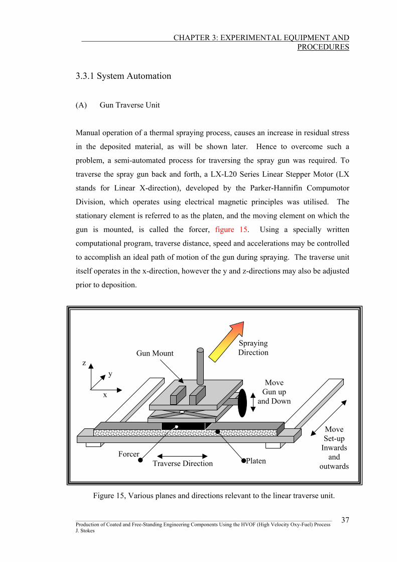
Manual operation of a thermal spraying process, causes an increase in residual stress
in the deposited material, as will be shown later. Hence to overcome such a
problem, a semi-automated process for traversing the spray gun was required. To
traverse the spray gun back and forth, a LX-L20 Series Linear Stepper Motor (LX
stands for Linear X-direction), developed by the Parker-Hannifin Compumotor
Division, which operates using electrical magnetic principles was utilised. The
stationary element is referred to as the platen, and the moving element on which the
gun is mounted, is called the forcer, figure 15. Using a specially written
computational program, traverse distance, speed and accelerations may be controlled
to accomplish an ideal path of motion of the gun during spraying. The traverse unit
itself operates in the x-direction, however the y and z-directions may also be adjusted
prior to deposition.
z y
x
Forcer
Gun Mount
Platen
Spraying Direction
Move Gun up
and Down
Move Set-up
Inwards and
outwardsTraverse Direction
Figure 15, Various planes and directions relevant to the linear traverse unit. ________________________________________________________________________________________________ Production of Coated and Free-Standing Engineering Components Using the HVOF (High Velocity Oxy-Fuel) Process J. Stokes
37
CHAPTER 3: EXPERIMENTAL EQUIPMENT AND
PROCEDURES
Depending on the component to be fabricated, a single axis (X-plane) in which the
gun would traverse from left to right, was deemed appropriate for the HVOF
process. A second axis (Y-plane) allows the gun mount, forcer and platen to be fixed
at various spraying distances, however this adjustment of distance is set before
deposition. An adjustable platform was designed to give various heights in the Y-
plane, which could be changed manually to align the guns’ nozzle opening to that of
the receiving substrate. A third axis (Z-plane) seemed less important, due to the
complexity of the automation movement and also due to the geometry of the
components to be fabricated.
The specification of the horizontal (X-plane) traversing unit stepper motor (described
later), depended on some considerations such as the load characteristics,
performance requirements and coupling techniques. The equipment comprised of a
forcer and platen unit which was purchased from the Compumotor Division, this was
mounted on an aluminium frame, the working principle and computational
programming of the individual parts of the Gun Traverse Unit is described in
Appendix 2.
(B) Third-Axis Directional Unit
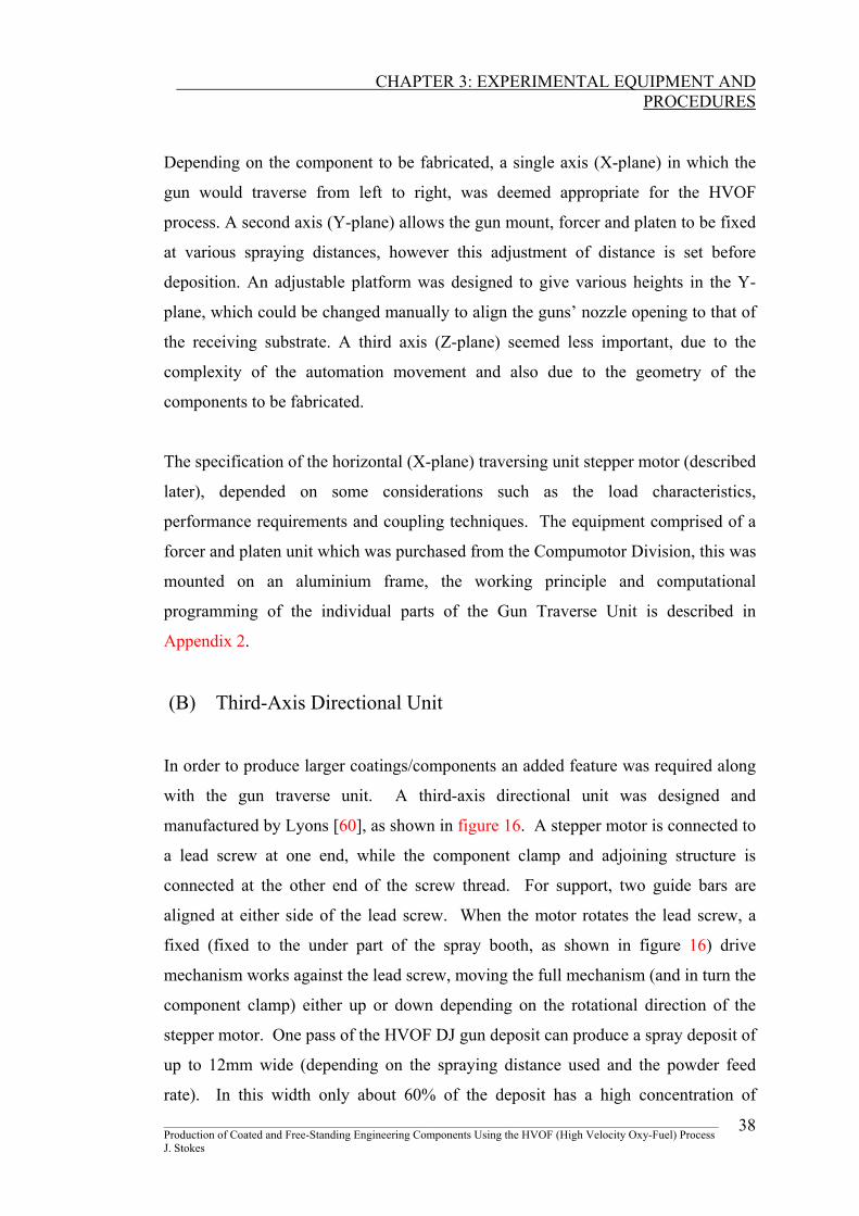
In order to produce larger coatings/components an added feature was required along
with the gun traverse unit. A third-axis directional unit was designed and
manufactured by Lyons [60], as shown in figure 16. A stepper motor is connected to
a lead screw at one end, while the component clamp and adjoining structure is
connected at the other end of the screw thread. For support, two guide bars are
aligned at either side of the lead screw. When the motor rotates the lead screw, a
fixed (fixed to the under part of the spray booth, as shown in figure 16) drive
mechanism works against the lead screw, moving the full mechanism (and in turn the
component clamp) either up or down depending on the rotational direction of the
stepper motor. One pass of the HVOF DJ gun deposit can produce a spray deposit of
up to 12mm wide (depending on the spraying distance used and the powder feed
rate). In this width only about 60% of the deposit has a high concentration of ________________________________________________________________________________________________ Production of Coated and Free-Standing Engineering Components Using the HVOF (High Velocity Oxy-Fuel) Process J. Stokes
38
CHAPTER 3: EXPERIMENTAL EQUIPMENT AND
PROCEDURES
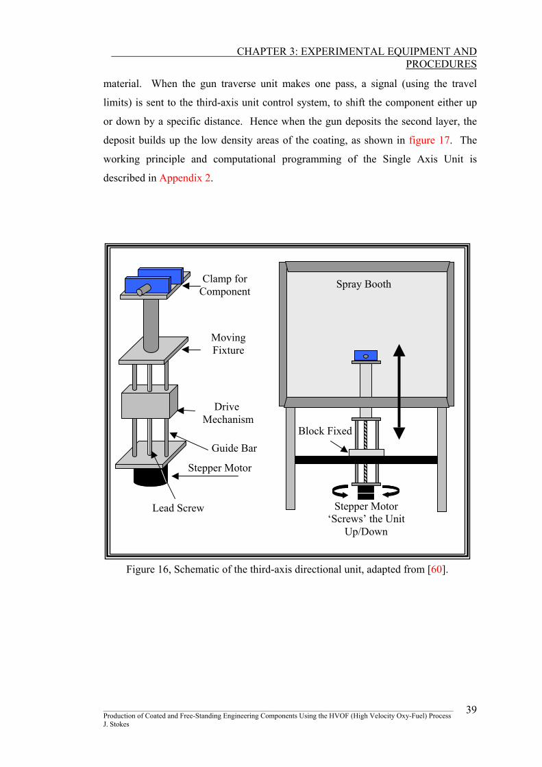
material. When the gun traverse unit makes one pass, a signal (using the travel
limits) is sent to the third-axis unit control system, to shift the component either up
or down by a specific distance. Hence when the gun deposits the second layer, the
deposit builds up the low density areas of the coating, as shown in figure 17. The
working principle and computational programming of the Single Axis Unit is
described in Appendix 2.
Guide Bar
Lead Screw
Spray Booth
Stepper Motor ‘Screws’ the Unit
Up/Down
Block Fixed
Stepper Motor
Drive Mechanism
Moving Fixture
Clamp for Component
Figure 16, Schematic of the third-axis directional unit, adapted from [60].
________________________________________________________________________________________________ Production of Coated and Free-Standing Engineering Components Using the HVOF (High Velocity Oxy-Fuel) Process J. Stokes
39
CHAPTER 3: EXPERIMENTAL EQUIPMENT AND
PROCEDURES
Pass 1
Pass 2
Situation where after the first pass, the third axis unit shifts the substrate
upwards for the second pass
Situation where the
gun deposits one pass
Figure 17, Schematic shows how shifting the substrate up/down
facilitates the deposition of large components.
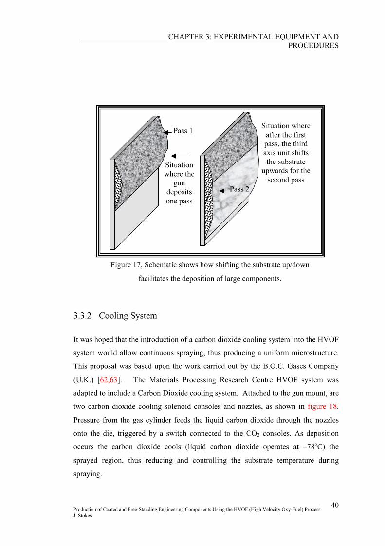
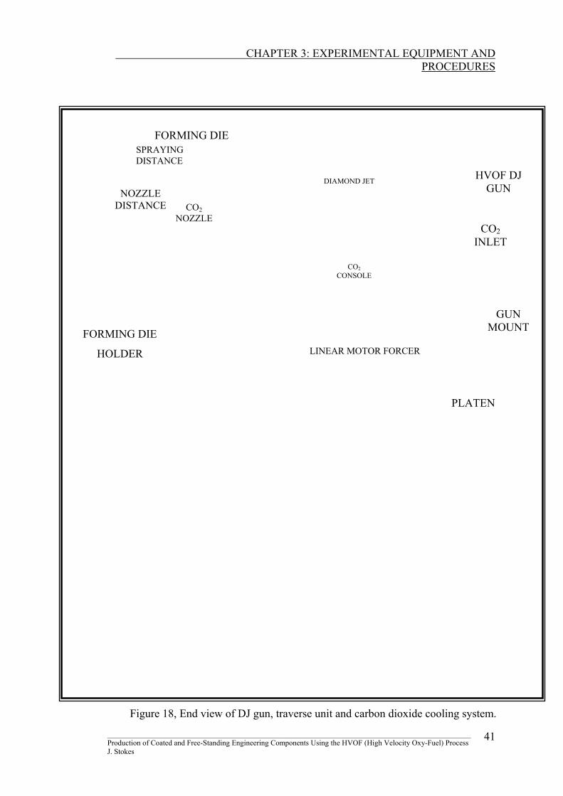
3.3.2 Cooling System It was hoped that the introduction of a carbon dioxide cooling system into the HVOF
system would allow continuous spraying, thus producing a uniform microstructure.
This proposal was based upon the work carried out by the B.O.C. Gases Company
(U.K.) [62,63]. The Materials Processing Research Centre HVOF system was
adapted to include a Carbon Dioxide cooling system. Attached to the gun mount, are
two carbon dioxide cooling solenoid consoles and nozzles, as shown in figure 18.
Pressure from the gas cylinder feeds the liquid carbon dioxide through the nozzles
onto the die, triggered by a switch connected to the CO2 consoles. As deposition
occurs the carbon dioxide cools (liquid carbon dioxide operates at –78oC) the
sprayed region, thus reducing and controlling the substrate temperature during
spraying.
________________________________________________________________________________________________ Production of Coated and Free-Standing Engineering Components Using the HVOF (High Velocity Oxy-Fuel) Process J. Stokes
40
CHAPTER 3: EXPERIMENTAL EQUIPMENT AND
PROCEDURES
________________________________________________________________________________________________ 41
HVOF DJ GUN NOZZLE
DISTANCE
SPRAYING DISTANCE
GUN MOUNTFORMING DIE
HOLDER
FORMING DIE
PLATEN
LINEAR MOTOR FORCER
CO2 NOZZLE
CO2 CONSOLE
CO2 INLET
METCO PERKIN ELMER
DIAMOND JET
Figure 18, End view of DJ gun, traverse unit and carbon dioxide cooling system.
Production of Coated and Free-Standing Engineering Components Using the HVOF (High Velocity Oxy-Fuel) Process J. Stokes
CHAPTER 3: EXPERIMENTAL EQUIPMENT AND
PROCEDURES
3.4 TEMPERATURE MEASEUREMENT SYSTEMS Continuous temperature measurement is essential to monitor the deposited material
temperature while spraying. Two systems of measurement were investigated, one an
optical method such as the pyroscope, and secondly a method using a series of
thermocouples, connected to a Pico TC-08 thermocouple converter.
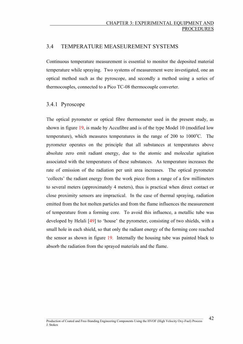
3.4.1 Pyroscope The optical pyrometer or optical fibre thermometer used in the present study, as
shown in figure 19, is made by Accufibre and is of the type Model 10 (modified low
temperature), which measures temperatures in the range of 200 to 1000oC. The
pyrometer operates on the principle that all substances at temperatures above
absolute zero emit radiant energy, due to the atomic and molecular agitation
associated with the temperatures of these substances. As temperature increases the
rate of emission of the radiation per unit area increases. The optical pyrometer
‘collects’ the radiant energy from the work piece from a range of a few millimeters
to several meters (approximately 4 meters), thus is practical when direct contact or
close proximity sensors are impractical. In the case of thermal spraying, radiation
emitted from the hot molten particles and from the flame influences the measurement
of temperature from a forming core. To avoid this influence, a metallic tube was
developed by Helali [49] to ‘house’ the pyrometer, consisting of two shields, with a
small hole in each shield, so that only the radiant energy of the forming core reached
the sensor as shown in figure 19. Internally the housing tube was painted black to
absorb the radiation from the sprayed materials and the flame.
________________________________________________________________________________________________ Production of Coated and Free-Standing Engineering Components Using the HVOF (High Velocity Oxy-Fuel) Process J. Stokes
42
CHAPTER 3: EXPERIMENTAL EQUIPMENT AND
PROCEDURES
Figure 19, Photo of the optical pyrometer used for temperature measurement and the metallic
tube holding the pyrometer sensor.
Optical Pyroscope Accufiber Pyroscope Unit
Pyrometer Sensor
Shielding
Tube
________________________________________________________________________________________________ Production of Coated and Free-Standing Engineering Components Using the HVOF (High Velocity Oxy-Fuel) Process J. Stokes
43
CHAPTER 3: EXPERIMENTAL EQUIPMENT AND
PROCEDURES
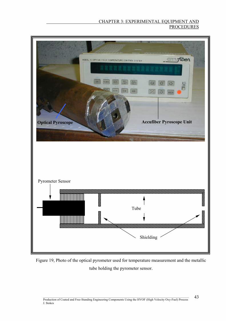
3.4.2 Temperature Logging Equipment The temperature logging equipment used in the study is known as Pico TC-08
Thermocouple to PC Converter (figure 20), developed by Pico Technology Limited.
The Pico TC-08, eight-channel thermocouple to personal computer converter can
measure temperatures in the range of –270 to 1800°C, and works for a wide range of
thermocouple types and probes. The converter is attached to the serial port of a
computer and a specific program allows eight individual temperatures to be
measured at intervals in the range of 1 millisecond to several hours. The results are
both tabulated and plotted for the operators’ convenience. The type of thermocouple
presently used is the K-type, with an overall range of –220 to 1300°C, and an
accuracy of 0.5°C. The thermocouples were fixed at various positions onto the
substrate for temperature measurement.
Attached ToThermocouple
To Computer Display
Figure 20, Photo of the Pico TC-08 thermocouple device used to measure deposition
temperature.
________________________________________________________________________________________________ Production of Coated and Free-Standing Engineering Components Using the HVOF (High Velocity Oxy-Fuel) Process J. Stokes
44
CHAPTER 3: EXPERIMENTAL EQUIPMENT AND
PROCEDURES
3.5 HVOF SPRAYING PROCEDURES The entire HVOF thermal spraying process used to produce WC-Co coatings and the
spray-formed components is described in the following sections: surface preparation,
pre-heat treatment, spraying process and the post-heat treatment.
3.5.1 Surface Preparation
(1) Adhesive Applications The substrate surface finish and integrity is crucial for the application of thermally
sprayed coatings, [64, 65]. Although surface cleanliness is impossible to achieve in
the scientific sense, nevertheless adequate surface treatment has proved to provide
sufficient bond strengths between the deposit material and the receiving substrate
[66]. Cleaning is generally carried out by eroding the surface by a harder material,
that is with the grit (sand) blasting unit, see report [34].
(2) Non-Adhesive Applications Adhesion of the deposit to the substrate may not always be required, such as where
forming a component is the purpose of spraying. In this situation the substrate acts
more as a die, than a supporting product. To effectively produced spray-formed
components, it is essential that the deposit adheres somehow to the substrate, but is
however easily removed afterwards.
One technique to achieve this is by placing an interlayer or, what is known as a
releasing layer, in between the substrate and the deposit. The releasing layer may be
thermally sprayed onto the substrate surface, or applied to the surface using other
means. Surface preparation would then be carried out before deposition to allow
adhesion of the deposit to the releasing layer. After deposition this layer would be
removed by melting it away in a furnace. Another method, introduced in the present
study, is to cover the internal surfaces of a forming die with aluminium foil, and
again this foil can be melted away during post-heat treatment.
________________________________________________________________________________________________ Production of Coated and Free-Standing Engineering Components Using the HVOF (High Velocity Oxy-Fuel) Process J. Stokes
45
CHAPTER 3: EXPERIMENTAL EQUIPMENT AND
PROCEDURES
Previous tests carried out by Helali et al. [30], show that aluminium acts as an ideal
releasing layer in the production of WC-Co components, as its melting temperature
can be incorporated into the post-heat treatment of the produced material. Helali et
al. [30] found that a layer of thickness 75µm is sufficient to ensure adhesion of the
deposit to the releasing layer and that melting the aluminium at 650oC, will release
the formed component from the substrate.
3.5.2 Pre-Heat Treatment
Moisture build up on the substrate surface may be removed by exposing the surface
to a high temperature, a process known as pre-heat treating. Thermal stresses occur
when there is a difference in the thermal expansion coefficient between the substrate
and the deposited material. Pre-heating the substrate may reduce or elevate thermal
stresses, dependent on the exposure temperature. The pre-heat temperature for a
steel substrate is usually within the range of 90 to 150oC [33], but tests have shown
[30], that a pre-heat temperature of 450oC reduces greater amounts of residual stress
built up in WC-Co coatings, compared to temperatures below 150oC. The pre-heat
temperature should be such, that the rate of expansion of the substrate and rate of
contraction of the impacting must be minimised in order to control the build up of
residual stress [43]. Pre-heating is carried out by igniting the gun (with a flint
lighter), and heating the substrate with the guns’ flame, up to the desired pre-heat
temperature prior to deposition.
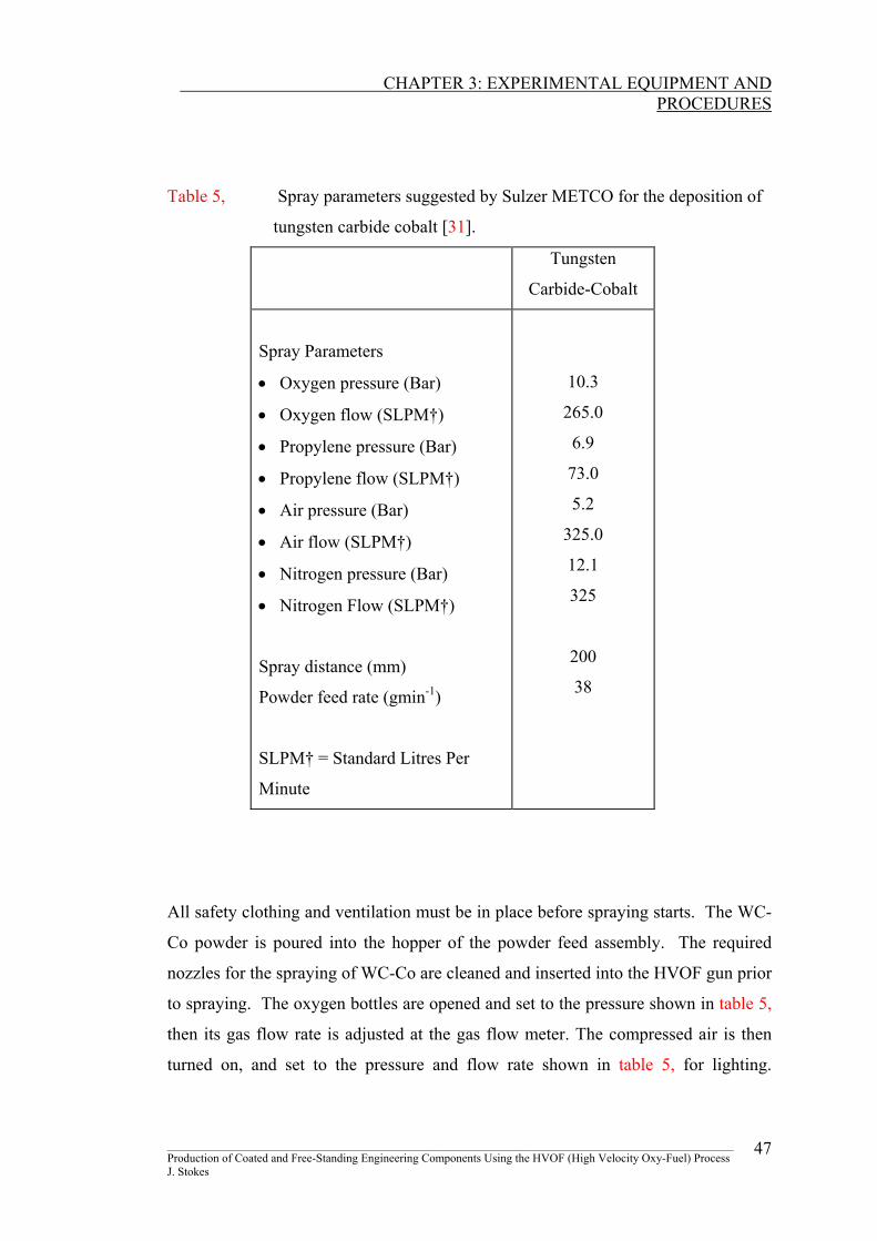
3.5.3 Spraying Process Spraying of a material depends on the thermal spraying process used and the type of
material being sprayed. In the case of the HVOF thermal spraying process, Sulzer
METCO have outlined recommended spraying parameters for the deposition of
Diamalloy 2003, WC-Co as shown in table 5 [31]. In terms of coating quality,
optimisation of these parameters is essential.
________________________________________________________________________________________________ Production of Coated and Free-Standing Engineering Components Using the HVOF (High Velocity Oxy-Fuel) Process J. Stokes
46
CHAPTER 3: EXPERIMENTAL EQUIPMENT AND
PROCEDURES
Table 5, Spray parameters suggested by Sulzer METCO for the deposition of
tungsten carbide cobalt [31].
Tungsten
Carbide-Cobalt
Spray Parameters
• Oxygen pressure (Bar)
• Oxygen flow (SLPM†)
• Propylene pressure (Bar)
• Propylene flow (SLPM†)
• Air pressure (Bar)
• Air flow (SLPM†)
• Nitrogen pressure (Bar)
• Nitrogen Flow (SLPM†)
Spray distance (mm)
Powder feed rate (gmin-1)
SLPM† = Standard Litres Per
Minute
10.3
265.0
6.9
73.0
5.2
325.0
12.1
325
200
38
All safety clothing and ventilation must be in place before spraying starts. The WC-
Co powder is poured into the hopper of the powder feed assembly. The required
nozzles for the spraying of WC-Co are cleaned and inserted into the HVOF gun prior
to spraying. The oxygen bottles are opened and set to the pressure shown in table 5,
then its gas flow rate is adjusted at the gas flow meter. The compressed air is then
turned on, and set to the pressure and flow rate shown in table 5, for lighting.
________________________________________________________________________________________________ Production of Coated and Free-Standing Engineering Components Using the HVOF (High Velocity Oxy-Fuel) Process J. Stokes
47
CHAPTER 3: EXPERIMENTAL EQUIPMENT AND
PROCEDURES
Propylene is then finally set to its parameters. The gun is then ignited and set up for
spraying the WC-Co by varying the air flow rate to 325 SLPM.
Nitrogen is allowed to flow through the powder feed unit and is also adjusted to its
parameters according to table 5. The powder is fed to the gun by switching on the
feed button on the gun. The flow rate of powder is then adjusted to 38gmin-1.
The spraying distance is controlled by the use of the linear motor, which also
controls the traverse speed of the deposit. The spraying temperature maybe
controlled, by using the carbon dioxide cooling system. After deposition, the
substrate and adjoining spray material are ready for post-heat treatment.
3.5.4 Post-heat Treatment Post-heat treatment of WC-Co components is used for two reasons; one to release
the component from the die and second to reduce the residual stress that had built up
during spraying. The post-heat treatment is carried out in the furnace under a
nitrogen atmosphere.
As previously described, the aluminium releasing layer is melted away in order to
remove a WC-Co component away from the forming die. Heating the die assembly
above the melting temperature of the aluminium (≈ 650oC) for a sufficient length of
time (eighty minutes according to Helali [49]), dissipates all the aluminium away
from the die and the spray-form component [30].
Post-heat treatment has been proved as an effective stress relief process, where
tungsten carbide-cobalt coatings or spray-formed components are elevated to
temperatures of 650oC [30, 67,68].
________________________________________________________________________________________________ Production of Coated and Free-Standing Engineering Components Using the HVOF (High Velocity Oxy-Fuel) Process J. Stokes
48
CHAPTER 3: EXPERIMENTAL EQUIPMENT AND
PROCEDURES
3.6 TEMPERATURE MEASUREMENT
Tests carried out by Helali [49] showed that the reliability of temperature readings
measured by the optical pyrometer was unsatisfactory. Temperature values were
inaccurate by as much as 25%, compared with readings measured using K-type
thermocouples. Therefore it will be important to either increase the accuracy of the
pyrometer or else to introduce a more reliable method of measurement.
3.6.1 Pyrometer Test
The pyrometer, which works on an optical measurement principle, was set up for
temperature calibration. Two tests were carried out; one measurement of a heated
metal and secondly measurement of spraying temperature.
(1) Measurement of a Heated Solid
Two K-type thermocouples were attached to one side of a solid stainless steel block.
The block was then placed into a furnace and raised to a temperature of 1000oC.
After heating, the block was removed from the furnace and placed in front of the
optical pyrometer (with the thermocouples facing the pyrometer) for temperature
measurement. Temperature values were recorded every second as the block cooled
by both devices (pyrometer and thermocouple TC-08 device).
(2) Spraying Temperature Measurement
The Diamond Jet HVOF gun was set up to spray tungsten carbide cobalt onto a
stainless steel substrate at a distance of 200mm. Again a thermocouple was attached
to the stainless steel just under the deposition zone, to acquire an approximate
spraying temperature, and the pyrometer was focused onto the deposition zone at a
distance of 200mm. Temperatures measured by both the pyrometer and the
thermocouple were then compared and analysed.
________________________________________________________________________________________________ Production of Coated and Free-Standing Engineering Components Using the HVOF (High Velocity Oxy-Fuel) Process J. Stokes
49
CHAPTER 3: EXPERIMENTAL EQUIPMENT AND
PROCEDURES
3.6.2 Thermocouple Temperature Calibration
Thermocouples are an efficient method of temperature measurement, however
measuring the temperature during deposition poses problems, as the deposit coats the
tip of the thermocouple, hence records incorrect readings. It is proposed as part of
the current research that the spraying temperature can be measured by extrapolation
from the temperature measured at the back of the substrate. The advantage of
determining a relationship between the temperatures across gradients of different
materials is that it allows temperature measurement to be made from the back of the
die which, through a calibration curve, give actual spraying temperatures in the
front-side of the die.
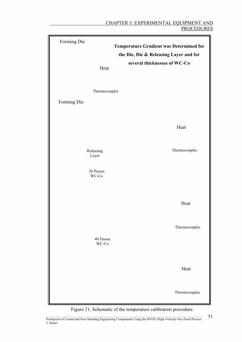
Based on the spray parameters given in [31], the Diamond Jet HVOF gun was fixed
at a spraying distance of 200mm from the gun nozzle and the forming die. Two
thermocouples were fixed onto the back and two onto the front-side of a forming die
to establish a temperature gradient across the substrate/die and various thicknesses of
deposit material as shown in figure 21. The temperature gradient was found by
heating the front-side of the forming die with the flame of the gun, and measuring
the temperature difference between the front and the back of the die and applied
coatings. The temperature gradients were determined for:
1. The forming die itself
2. The die with an aluminium releasing layer
3. The die, releasing layer and two thicknesses of WC-Co forming material
The temperature of the die and relevant coatings was allowed to stabilise (around ten
seconds) at each individual temperature, before values were recorded.
Using this method, spraying temperatures at various spraying distances were
measured, for both normal spraying, and spraying with forced cooling (using the
carbon dioxide cooling system).
________________________________________________________________________________________________ Production of Coated and Free-Standing Engineering Components Using the HVOF (High Velocity Oxy-Fuel) Process J. Stokes
50
CHAPTER 3: EXPERIMENTAL EQUIPMENT AND
PROCEDURES
________________________________________________________________________________________________ 51
Heat
Heat
Heat
Thermocouples
Thermocouples
40 PassesWC-Co
20 PassesWC-Co
Heat
Thermocouples
Thermocouples
Forming Die
Releasing Layer
Forming Die
Figure 21, Schematic of the temperature calibration procedure.
Temperature Gradient was Determined for
the Die, Die & Releasing Layer and for
several thicknesses of WC-Co
Production of Coated and Free-Standing Engineering Components Using the HVOF (High Velocity Oxy-Fuel) Process J. Stokes
CHAPTER 3: EXPERIMENTAL EQUIPMENT AND
PROCEDURES
3.6.3 Temperature Dependence On Spraying Distance
This section investigated whether deposition temperature was a function of spraying
distance. If one measures the temperature of the HVOF flame, they will find that the
temperature decreases with increased distance from the HVOF guns head, hence the
particles decreases in temperature as they move from the gun’s nozzle [69].
With the use of the linear traverse unit (allowing for exact spraying distances),
thermal spraying was carried out on stainless steel substrates at spraying distances
from 125 to 260mm (at intervals of 10mm). WC-Co was sprayed at each distance,
with and without forced cooling (using the carbon dioxide cooling system), to
measure the resulting spraying temperature. At each distance the temperature at the
back of the substrate (using three thermocouples) was measured during deposition.
Using the temperature calibration procedure outlined in the previous section, a
spraying temperatures was determined for each spray distance. The test was carried
out three times at each distance.
________________________________________________________________________________________________ Production of Coated and Free-Standing Engineering Components Using the HVOF (High Velocity Oxy-Fuel) Process J. Stokes
52
CHAPTER 3: EXPERIMENTAL EQUIPMENT AND
PROCEDURES
3.7 COATING CHARACTERISATION EQUIPMENT
Observation of a specimen visually either macro- or microscopically, enable the
detection of large defects (adhesion failure, cracks and so on). There are numerous
optical techniques available, including the Optical Microscope (OM), Scanning
Electron Microscope (SEM) and X-ray Diffraction (XRD). Further information on
the operation of these optical techniques may be found in my additional report [34].
The full coating microstructure description contains such information as; chemical
composition (at the macro and microstructure scale), grain morophology and its
orientation, defects (such as voids or second phases) and coating thicknesses.
Mechanical properties such as microhardness, tensile strength, fracture strength,
elastic modulus, toughness, porosity, and wear resistance can all be identified using
optical techniques [70]. The report focuses on the relationship between residual
stress and deposition thickness and measurement of these two parameters depend on
the use of characterisation equipment such as optical techniques.
Microstructural characterisation using an optical microscope has now become a
standard test in a coating/formed component’s development (post deposition).
However, prior to microscopic observation, the sprayed piece must be prepared
metallographically. Observation of the longitudinal or traverse section of the coating
(perpendicular to the coating surface) provides information about the surface of the
substrate and about the changes that occurred in the microstructure through the
deposit. Care has to be taken to ensure the proper grinding and polishing procedure
is chosen. Bleamishes resulting from poor preparation include scratches,
deformation, smearing, edge rounding, pull-out, cracks, contamination, embedded
abrasive, lapping tracks and staining, according to Glancy (1994) [71]. Extensive
details on the grinding, polishing and etching procedures are provided in my report
[34].
________________________________________________________________________________________________ Production of Coated and Free-Standing Engineering Components Using the HVOF (High Velocity Oxy-Fuel) Process J. Stokes
53
CHAPTER 3: EXPERIMENTAL EQUIPMENT AND
PROCEDURES
3.8 YOUNG’S MODULUS MEASUREMENT
The elastic moduli of a coating and the stresses at which material failure occurs are
very important in the determination of a coating’s reliability. According to
Pawlowski [69], Young’s modulus is influenced by porosity, hence post-heat
treatment which may reduce porosity can thus increase stiffness. Young’s modulus
determination of a coating is difficult, as in general the coating is attached to a
substrate, however there are many methods using bending theory used to calculate
these properties. In residual stress determination an elastic modulus (Ec) and
Poisson’s ratio (νc) for a coating is required, hence determination of these properties
is crucial at this point of the report.
3.8.1 Cantilever Beam Method
There are other methods of measuring the stiffness and Poisson’s ratio of the coating.
Rybicki, et al. [202, 203] describes a cantilever beam method for measuring both of
these properties. Figure 22 shows the experimental set up used to determine the
Young’s modulus and Poisson’s ratio, for thermally sprayed coatings. Two biaxial
strain gauges are placed on the coating surface, and two placed directly opposite on
the substrate side. A force is applied to the end of the substrate, thus the strain is
measured to yield the two properties using the ‘Laminate Plate Theory’.
The laminate plate theory is used in the cantilever beam method, to relate the
unknown Ec (coating stiffness) and νc (coating Poisson’s ratio), to the loading of the
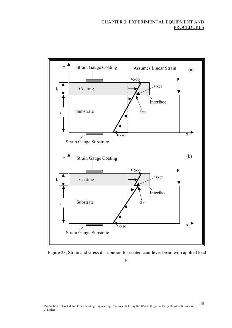
gauge sections. This theory assumes a linear strain distribution through the thickness
of the coated cantilever beam, and plane stress conditions. Figure 23 shows a
schematic of the strain (a) and stress (b) distribution respectively, for a coated
cantilever with applied load.
________________________________________________________________________________________________ Production of Coated and Free-Standing Engineering Components Using the HVOF (High Velocity Oxy-Fuel) Process J. Stokes
54

CHAPTER 3: EXPERIMENTAL EQUIPMENT AND
PROCEDURES
Strain Gauge
Weight
Substrate
Coating
Vice
Multi Channel Strain Indicator
z x
Figure 22, The Cantilever approach for measuring coating stiffness.
The difference in mechanical properties between the coating and substrate introduces
stress discontinuity at the interface. The equilibrium equations for the coated beam
are as follows [72,73], where the stresses (σX in the x-direction, σY in the y-
direction) are related to the forces (FX in the x-direction, FY in the y-direction) and
moments (MX in the x-direction, MY in the y-direction) by:
0 = FX = dzdy ∫∫ Xσ XM = MX = ∫∫ Zσ zdzdy Equation 4
0 = FY = dzdy 0 = M∫∫ Yσ Y = ∫∫ Yσ zdzdy Equation 5
For the coated beam,
FX = w(σXSI + σXSG )2st + w(σXCI + σXCG )
2ct Equation 6
________________________________________________________________________________________________ Production of Coated and Free-Standing Engineering Components Using the HVOF (High Velocity Oxy-Fuel) Process J. Stokes
55
CHAPTER 3: EXPERIMENTAL EQUIPMENT AND
PROCEDURES
MX = w [σXSG 2
2st + (σXSI - σXSG )
3
2st
)
+ w [σXCI (tc )( 2st
+ 6ct ) + σXCG (tc )( 2
st+
3ct )] Equation 7
FY = w(σYSI + σYSG )2st + w(σYCI + σYCG )
2ct Equation 8
MY = w [σYSG 2
2st + (σYSI - σYSG )
3
2st
)
+ w [σYCI (tc )( 2st
+ 6ct ) + σYCG (tc )( 2
st+
3ct )] Equation 9
where w is the width of both the coating and substrate, M is the applied bending
moment at gauge location, P the applied load, ts and tc are the thickness of the
substrate and coating respectively, εXCG and εYCG are the longitudinal and respective
traverse strain gauge readings on the coating, εXSG and εYSG are the longitudinal and
respective traverse strain gage reading on the substrate, εXCI and εYCI are the
longitudinal and respective traverse strain at the coating interface, εXSI and εYSI are
the longitudinal and respective traverse strain at the substrate interface, σXCG and
σYCG are the longitudinal and respective traverse stress gage reading on the coating,
σXSG and σYSG are the longitudinal and respective traverse stress gage reading on the
substrate, σXCI and σYCI are the longitudinal and respective traverse stress at the
coating interface, σXSI and σYSI are the longitudinal and respective traverse stress at
the substrate interface.
The surface stresses, σCG and σSG, are related to the strains and the mechanical
properties of the coating and substrate from the following:
________________________________________________________________________________________________ Production of Coated and Free-Standing Engineering Components Using the HVOF (High Velocity Oxy-Fuel) Process J. Stokes
56
CHAPTER 3: EXPERIMENTAL EQUIPMENT AND
PROCEDURES
σXCG = )1( 2
c
cEν−
(εXCG + νc εYCG) Equation 10
σXSG = )1( 2
s
sEν−
(εXSG + νs εYSG) Equation 11
where νs and νc are the Poisson’s ratio for the substrate and coating respectively, Es
and Ec are the Young’s modulus for the substrate and coating respectively, the
surface strains, εXCG, εYCG, εXSG and εYSG, are measured with the strain gages. The
interface stresses can be calculated from:
σXCI = )1( 2
c
cEν−
(εXCI + νc εYCI) Equation 12
σXSI = )1( 2
s
sEν−
(εXSI + νs εYSI) Equation 13
where the interface strains, εXCI, εYCI, εXSI and εYSI, can be found from the
assumption of a linear strain distribution from the surface strains. Test were carried
out on coated (WC-Co) aluminium and stainless steel substrates, then two of the four
equilibrium equations were used to solve the stiffness and Poisson’s ratio of the
coating.
The least squares method minimizes a function composed of four equilibrium
equations. The function φ(Ec,νc) is based on minimizing the maximum stress
difference. MP is the applied force P times the distance between the load location
and the gauge location.
φ(Ec,νc) = ( )36
2cTH + [Fx
2 + Fy2] + [MX +MP] + [MY]2 Equation 14
________________________________________________________________________________________________ Production of Coated and Free-Standing Engineering Components Using the HVOF (High Velocity Oxy-Fuel) Process J. Stokes
57
CHAPTER 3: EXPERIMENTAL EQUIPMENT AND
PROCEDURES
Assumes Linear Strain
(b)
(a)
x
z
P
Interface
σXSI
σXCI σXCG
σXSG
Strain Gauge Substrate
Strain Gauge Coating
Coating
Substrate ts
tc
x
z
P
Interface
εXSI
εXCI εXCG
εXSG
Strain Gauge Substrate
Strain Gauge Coating
Coating
Substrate ts
tc
Figure 23, Strain and stress distribution for coated cantilever beam with applied load
P.
________________________________________________________________________________________________ Production of Coated and Free-Standing Engineering Components Using the HVOF (High Velocity Oxy-Fuel) Process J. Stokes
58
CHAPTER 3: EXPERIMENTAL EQUIPMENT AND
PROCEDURES
3.8.2 Tension Testing Method
As the current research strives to produce free-standing WC-Co components, the
research also endeavours to produce free-standing WC-Co tensile specimens, and
together with the standard ASTM E8M [74]. The production of free-standing tensile
specimens is described in a later section and successful specimens were subjected to
a tensile load, to measure the Young’s modulus of the material.
3.8.3 Other Determination Techniques
There are other techniques used to measure the stiffness of a coating, such as the
three/four point bend test, indentation and the curved specimen deflection tests,
however neither of these tests were used in the current research. In the three/four
point experimental test the coated or free-standing sample is placed on two knife
edges and force is applied through a third knife edge (three point test) or two knife
edges (four point test). The bend test can be monitored acoustically to detect the
crack formation (especially for brittle ceramic coatings) [75]. The elastic modulus is
found from the applied load and the deflection measured when the deposit fails.
The indentation test and a curved specimen deflection test, are two Young’s modulus
measurement techniques, used to determine this parameter in both the perpendicular
and parallel directions respectively [76]. The indentation test involves, drawing a
diamond hemispherical indentor with known radius across the coating surface. After
scratching under various loads, the depth of scar is measured by a stylus (used to
measure surface roughness). The radius of contact between the indentor and the
coating surface, together with Hertz’s contact theory, calculates the Young’s
modulus perpendicular to the coating plane [76]. The measurement process for
Young’s modulus parallel to the coating plane, involves spraying a cylindrical stand-
alone component. The component is compressed in the radial direction where the
load is measured. Using this technique, the Young’s modulus is measured in
accordance to the deflection of a curved beam theory.
________________________________________________________________________________________________ Production of Coated and Free-Standing Engineering Components Using the HVOF (High Velocity Oxy-Fuel) Process J. Stokes
59
CHAPTER 3: EXPERIMENTAL EQUIPMENT AND
PROCEDURES
3.9 RESIDUAL STRESS MEASUREMENT
Residual stress creates the most difficulty in the production of thick spray formed
components. It is important to be able to measure the residual stress within a deposit
in order to control and reduce its build up by varying the spray parameters. Residual
stress in thermally sprayed coatings may be measured by many techniques including
a simple method using the modified ‘Almen’ test, similar to that outlined in
SAEJ443 [77], Clyne’s Method and the X-ray diffraction and hole drilling methods
[78].
3.9.1 The Almen Test Method
John O. Almen developed this technique primarily for measuring shot peening
intensity. It was observed that shot peening a substrate generated induced stresses,
which could be measured by the resulting substrate curvature. Further tests have
shown that the same procedure may be used to measure residual stress in thermally
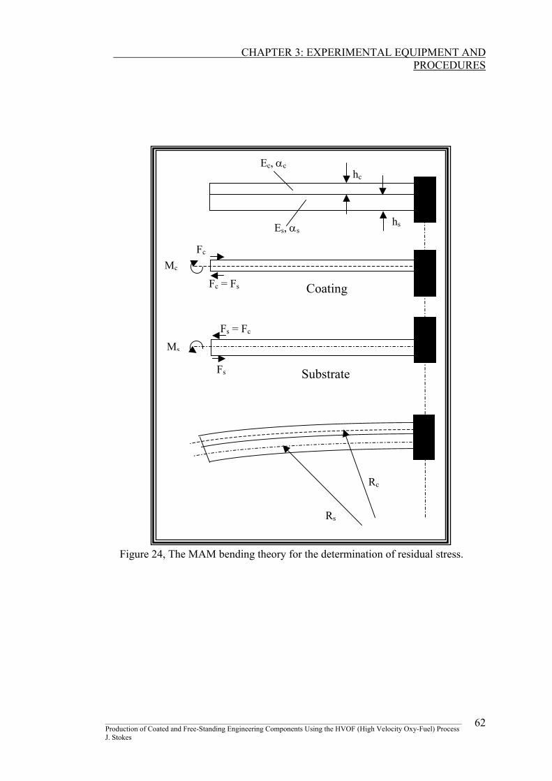
sprayed coatings, known as the ‘Modified Almen Method’ (MAM) [79]. The free
body diagram in figure 24, illustrates the bending theory used to determine the
residual stress of the coating. The forces acting on the coating and the substrate, are
denoted by Fc and Fs respectively; Mc and Ms are the corresponding bending
moments. Es, As and hs are the properties Young’s modulus, area and height of the
substrate respectively, and similarly Ec, Ac and hc are the properties for the coating.
The coefficient of expansion for the coating and substrate are given as αc and αs. Rc
and Rs are the resulting bending radius values for the coating and the substrate
respectively. The bending theory and numerical formulation is described in
Appendix 3 [80].
________________________________________________________________________________________________ Production of Coated and Free-Standing Engineering Components Using the HVOF (High Velocity Oxy-Fuel) Process J. Stokes
60
CHAPTER 3: EXPERIMENTAL EQUIPMENT AND
PROCEDURES
Once all of the dimensions and parameters are known (including the Young’s
modulus of the coating), the average stress in a coating may be found using equation
15:
∴ σAverage = cA
F =
+
∆−+−−
c
sscc
scsccs
s
s
c
c
A
hEhEAhEET
R
h
R
h.)(22 αα
Equation 15
However one may be interested in the stress distribution across the coating and
substrate, and may have to rely on the more simplistic approach of applying beam
theory. Using this the stress at any point in the coating may be found by the
following expression:
σxc = -R
yEc Equation 16
The negative sign indicates that a positive bending moment produces a negative
curvature. The position relative to the neutral axis (that is y), is positive if working
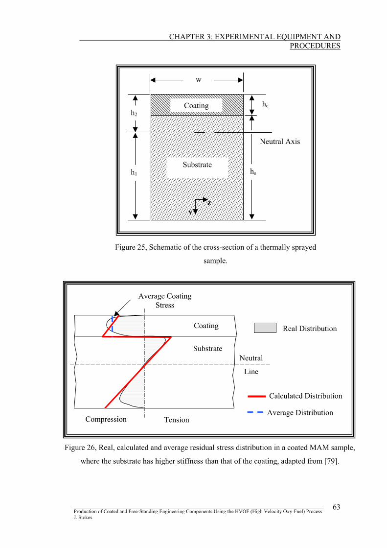
above the neutral axis and negative if below, with reference to figure 25. Figure 26
shows the expected differences between the average coating stress, the measured
distributed stress and the real distribution [209] in a thermally sprayed sample.
Due to the high temperatures experienced by thermal sprayed materials, the Young’s
modulus for a coating differs to that of material produced by other manufacturing
techniques. Hence, selection of an appropriate coating Young’s modulus value for
equations 15 and 16, is vital to establish a stress distribution through the coating.
________________________________________________________________________________________________ Production of Coated and Free-Standing Engineering Components Using the HVOF (High Velocity Oxy-Fuel) Process J. Stokes
61
CHAPTER 3: EXPERIMENTAL EQUIPMENT AND
PROCEDURES
Fs = Fc
Fc = Fs
hs
hc
Substrate
Coating
Ms
Fs
Mc Fc
Es, αs
Ec, αc
Rs
Rc
Figure 24, The MAM bending theory for the determination of residual stress.
________________________________________________________________________________________________ Production of Coated and Free-Standing Engineering Components Using the HVOF (High Velocity Oxy-Fuel) Process J. Stokes
62
CHAPTER 3: EXPERIMENTAL EQUIPMENT AND
PROCEDURES
Neutral Axis
yz
hc
hs
w
Substrate
Coating h2
h1
Figure 25, Schematic of the cross-section of a thermally sprayed
sample.
Average Coating Stress
Neutral
Line
Substrate
Coating
Compression Tension Average Distribution
Calculated Distribution
Real Distribution
Figure 26, Real, calculated and average residual stress distribution in a coated MAM sample,
where the substrate has higher stiffness than that of the coating, adapted from [79].
________________________________________________________________________________________________ Production of Coated and Free-Standing Engineering Components Using the HVOF (High Velocity Oxy-Fuel) Process J. Stokes
63
CHAPTER 3: EXPERIMENTAL EQUIPMENT AND
PROCEDURES
3.9.2 Clyne’s Analytical Method A closer look at the Modified Almen test Method reveals that this method does not
account for ‘Misfit Strain’. The main interest in this thesis lies in the stress levels,
which are generated within the surface coating (and the substrate). It is useful
therefore to consider the situation in terms of misfit strains, that is, relative
differences between the stress-free dimensions of various layers. The simplest
system is composed of just two layers, the coating and the substrate, but it may be
appropriate (particularly for thick coatings) to consider the coating as being
deposited as a series of layers. A further general point is that it can be very
instructive to note how the system will adopt a curvature as a result of the imposition
of a misfit strain. This can be useful, not only in helping to understand the mechanics
of stress generation, but also for using curvature monitoring to measure residual
stress levels.
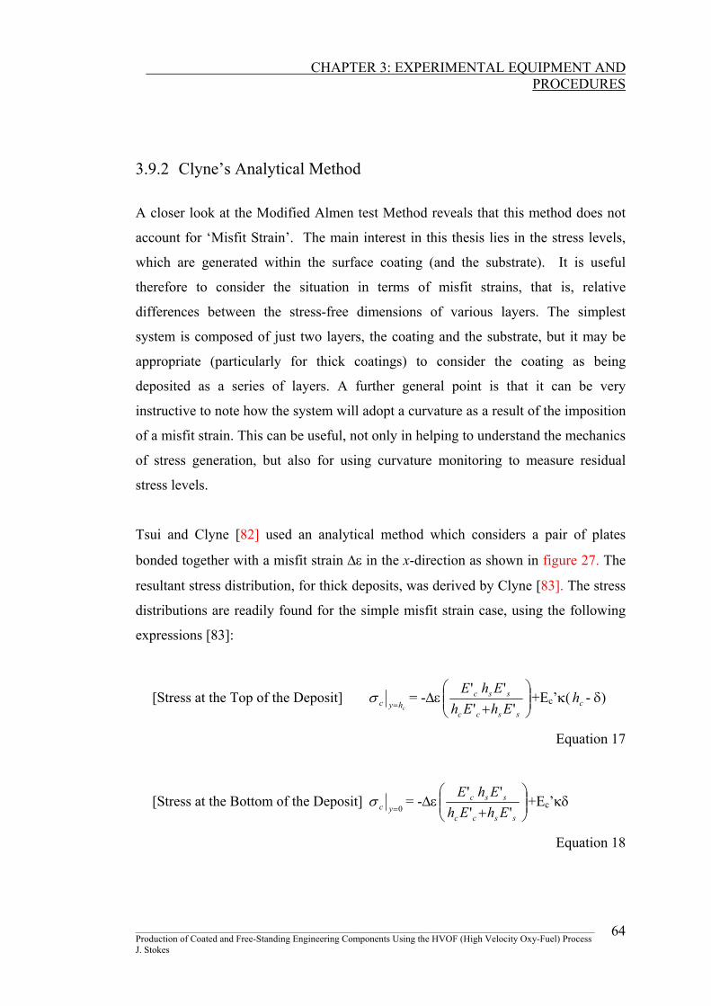
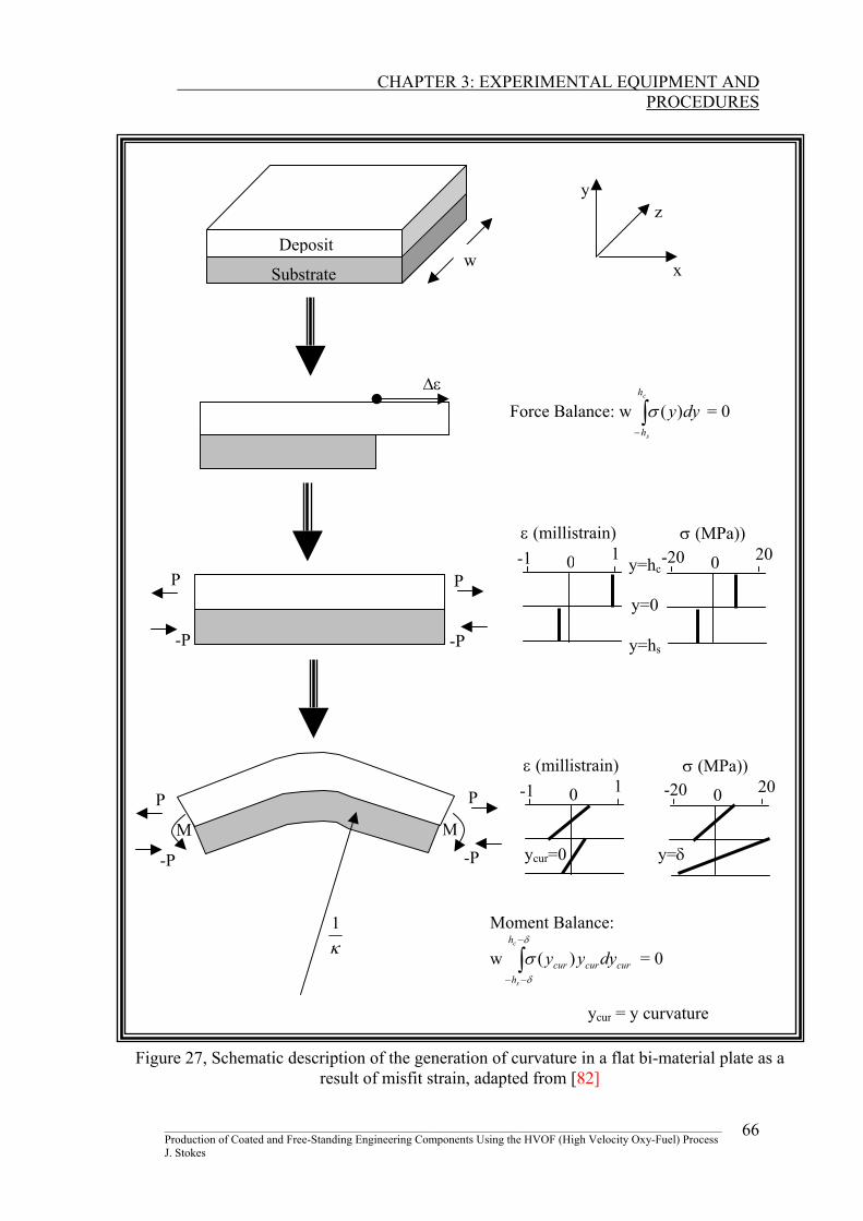
Tsui and Clyne [82] used an analytical method which considers a pair of plates
bonded together with a misfit strain ∆ε in the x-direction as shown in figure 27. The
resultant stress distribution, for thick deposits, was derived by Clyne [83]. The stress
distributions are readily found for the simple misfit strain case, using the following
expressions [83]:
[Stress at the Top of the Deposit] chyc =
σ = -∆ε
+ sscc
ssc
EhEhEhE
''''
+Ec’κ( - δ)
Equation 17
ch
[Stress at the Bottom of the Deposit] 0=ycσ = -∆ε
+ sscc
ssc
EhEhEhE
''''
+Ec’κδ
Equation 18
________________________________________________________________________________________________ Production of Coated and Free-Standing Engineering Components Using the HVOF (High Velocity Oxy-Fuel) Process J. Stokes
64
CHAPTER 3: EXPERIMENTAL EQUIPMENT AND
PROCEDURES
[Stress at the Top of the Substrate] 0=ysσ = ∆ε
+ sscc
ssc
EhEhEhE
''''
- Es’κδ
Equation 19
[Stress at the Bottom of the Substrate]shys −=
σ = ∆ε
+ sscc
ssc
EhEhEhE
''''
- Es’κ ( + δ)
Equation 20
sh
Where σc and σs are the respective stresses in the coating and substrate. ∆ε is given
as:
∆ε = (αs − αc)∆Τ Equation 21
Where α c and αs are the respective coefficients of thermal expansions for the
substrate and coating, and ∆T is the difference in temperature. Ec’ and Es’ are given
as follows:
Ec’ = ( )c
cEν−1
Equation 22
Es’ = ( )s
sEν−1
Equation 23
Where Ec and Es are the respective coating and substrate stiffnesses. κ is the
curvature of the beam (given as R1 , where R is found in a similar way to that shown
in the MAM test) and δ is the overall deflection of the beam.
________________________________________________________________________________________________ Production of Coated and Free-Standing Engineering Components Using the HVOF (High Velocity Oxy-Fuel) Process J. Stokes
65
CHAPTER 3: EXPERIMENTAL EQUIPMENT AND
PROCEDURES
∫−
c
s
h
h
dyy)(σ
κ1
∫−
−−
δ
δ
σc
s
h
hcurcurcur dyyy )( =
∆ε Force Balance: w = 0
w
y
x
z
Deposit
Substrate
P
-P
P
-P
-1 1 0
ε (millistrain) -y=hc
y=0
y=hs
20 200
σ (MPa))
-1 1 0
ε (millistrain) -20 200
σ (MPa))
ycur=0 y=δ
P
-P
P
-P
M M
Moment Balance:
w 0
ycur = y curvature
Figure 27, Schematic description of the generation of curvature in a flat bi-material plate as a result of misfit strain, adapted from [82]
________________________________________________________________________________________________ Production of Coated and Free-Standing Engineering Components Using the HVOF (High Velocity Oxy-Fuel) Process J. Stokes
66
CHAPTER 3: EXPERIMENTAL EQUIPMENT AND
PROCEDURES
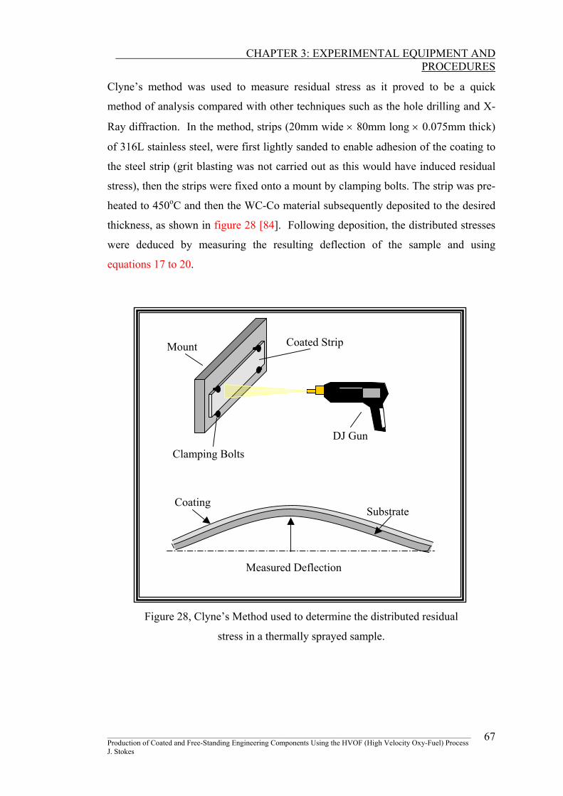
Clyne’s method was used to measure residual stress as it proved to be a quick
method of analysis compared with other techniques such as the hole drilling and X-
Ray diffraction. In the method, strips (20mm wide × 80mm long × 0.075mm thick)
of 316L stainless steel, were first lightly sanded to enable adhesion of the coating to
the steel strip (grit blasting was not carried out as this would have induced residual
stress), then the strips were fixed onto a mount by clamping bolts. The strip was pre-
heated to 450oC and then the WC-Co material subsequently deposited to the desired
thickness, as shown in figure 28 [84]. Following deposition, the distributed stresses
were deduced by measuring the resulting deflection of the sample and using
equations 17 to 20.
Substrate Coating
Measured Deflection
DJ Gun
Coated Strip
Clamping Bolts
Mount
Figure 28, Clyne’s Method used to determine the distributed residual
stress in a thermally sprayed sample.
________________________________________________________________________________________________ Production of Coated and Free-Standing Engineering Components Using the HVOF (High Velocity Oxy-Fuel) Process J. Stokes
67
CHAPTER 3: EXPERIMENTAL EQUIPMENT AND
PROCEDURES
3.9.3 X-Ray Diffraction Stress Measurement
X-ray Diffraction (XRD) offers unparalleled accuracy in the measurement of atomic
spacing, therefore it is an ideal choice in the determination of strain states in thin
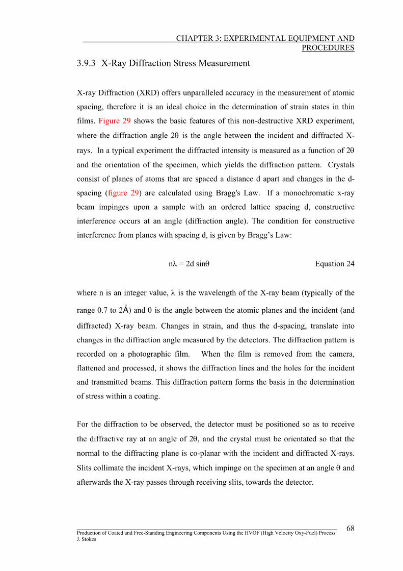
films. Figure 29 shows the basic features of this non-destructive XRD experiment,
where the diffraction angle 2θ is the angle between the incident and diffracted X-
rays. In a typical experiment the diffracted intensity is measured as a function of 2θ
and the orientation of the specimen, which yields the diffraction pattern. Crystals
consist of planes of atoms that are spaced a distance d apart and changes in the d-
spacing (figure 29) are calculated using Bragg's Law. If a monochromatic x-ray
beam impinges upon a sample with an ordered lattice spacing d, constructive
interference occurs at an angle (diffraction angle). The condition for constructive
interference from planes with spacing d, is given by Bragg’s Law:
nλ = 2d sinθ Equation 24
where n is an integer value, λ is the wavelength of the X-ray beam (typically of the
range 0.7 to 2Å) and θ is the angle between the atomic planes and the incident (and
diffracted) X-ray beam. Changes in strain, and thus the d-spacing, translate into
changes in the diffraction angle measured by the detectors. The diffraction pattern is
recorded on a photographic film. When the film is removed from the camera,
flattened and processed, it shows the diffraction lines and the holes for the incident
and transmitted beams. This diffraction pattern forms the basis in the determination
of stress within a coating.
For the diffraction to be observed, the detector must be positioned so as to receive
the diffractive ray at an angle of 2θ, and the crystal must be orientated so that the
normal to the diffracting plane is co-planar with the incident and diffracted X-rays.
Slits collimate the incident X-rays, which impinge on the specimen at an angle θ and
afterwards the X-ray passes through receiving slits, towards the detector.
________________________________________________________________________________________________ Production of Coated and Free-Standing Engineering Components Using the HVOF (High Velocity Oxy-Fuel) Process J. Stokes
68
CHAPTER 3: EXPERIMENTAL EQUIPMENT AND
PROCEDURES
Atomic planes
Diffracted crystallite
θ
Incident X-Rays
d
2θDiffracted
X-rays
Diffracted X-rays
2θ
Detector
Coating Substrate
Incident X-Rays
Figure 29, Basic features of a typical XRD experiment.
Since atomic spacings are accurately measured with XRD, it can be used as a
method of characterising homogeneous and inhomogeneous strains [85]. The strain
in the crystal lattice is measured and the residual stress producing the strain is
calculated, assuming a linear elastic distortion of the crystal lattice [86,87]. To
determine the stress, the strain in the crystal lattice must be measured for at least two
precisely known orientations relative to the sample surface. Therefore, X-ray
diffraction residual stress measurement is applicable to materials that are crystalline,
relatively fine grained, and produce diffraction from any orientation of the sample
surface.
________________________________________________________________________________________________ Production of Coated and Free-Standing Engineering Components Using the HVOF (High Velocity Oxy-Fuel) Process J. Stokes
69
CHAPTER 3: EXPERIMENTAL EQUIPMENT AND
PROCEDURES
The diffractometer used in the current study (Siemens Diffrac-500 XRD) has a
diffraction scanning range from –110 to +165 degrees for 2θ. Generally the machine
is set up according to the parameters detailed with the equipment and initially a
broad scan is carried out to find a chosen peak with the highest intensity (highest 2θ
angle). The sample is placed on a holder and is allowed to rotate at any angle ψ.
The process involves measuring various values of strain (εφψ) in multiple ψ
directions, where ψ is chosen so that the corresponding sin2ψ are equally spaced.
The result is given as a graph of sin2ψ (intensity) against εφψ (Two Theta). From the
graph, the slope of the line which best fits the measured points is calculated. The
residual stress in the coating is given by measuring the slope for two or more
different angles of ψ, and substituting into the following equation, derived (see
Appendix 4) from the assumption that the principal stresses exist in the plane of the
surface [88]:
σφ = ν+1
E (Slope of Graph) Equation 25
Where σφ is the stress result, E is the Young’s modulus of the coating/deposit and ν
is the Poisson’s ratio of the coating.
________________________________________________________________________________________________ Production of Coated and Free-Standing Engineering Components Using the HVOF (High Velocity Oxy-Fuel) Process J. Stokes
70
CHAPTER 3: EXPERIMENTAL EQUIPMENT AND
PROCEDURES
3.9.4 The Hole Drilling Method
Residual stress may also be measured using another method, known as the hole
drilling method. This method is “semi-destructive” as localised damage is done to
the coating surface. The strain gauge rosettes used in the study were the CEA-06-
062UM-120 precision strain gages, which are constructed of self-temperature-
compensated foil on a flexible polymide carrier and incorporate a centering target for
use with a precision milling guide. Their characteristics are:
• Resistance in Ohms at 24 °C = 120.0 ± 0.4%
• Gage factor at 24 °C = 2.07 ± 1.0%
• Temperature range from –100 °C to 350 °C
• Strain limits = 3%
The rosette strain gauge measures strain in three directions, 0o, 45o and 90° (or
another type at 0o, 60o and 120o), as described in ASTM E1561 [89] while the central
region is cut away. The rosettes (rectangular shape 12.2 x 9.6 mm2) have the grid
center line diameter of 5.13 mm and the length of each strain gage is 1.57 mm. The
gauge and the surface of the coating was thoroughly prepared before the gauge is
attached. Preparation to the surface entailed rubbing fine emery paper to remove any
surface contamination. An adhesive was then used to bond the gauge to the surface.
The test is carried out by connecting the strain gauge to a strain-recording instrument
(P-3500). The hole is drilled through the coating/deposit via the central region of the
strain gauge to relax the residual stress in the material being measured [90].
The RS-200 Milling Guide (MicroMeasurements, USA) is one high precision
instrument for residual stress analysis by the hole drilling method and was the unit
used in the current study. A carbide precision cutter, powered by a high-speed air
turbine unit (speeds of 300000 revolutions per minute at clean air pressures of 3atm),
was used to mill the hole. Milling was carried out until the depth of the milled hole
was equal to a distance of 0.4 of the mean gauge circle diameter (D), to ensure total
________________________________________________________________________________________________ Production of Coated and Free-Standing Engineering Components Using the HVOF (High Velocity Oxy-Fuel) Process J. Stokes
71
CHAPTER 3: EXPERIMENTAL EQUIPMENT AND
PROCEDURES
relaxation of residual stress, or through the thickness, where the total thickness is
less than 1.2 D.
Residual stress is calculated using Kirsch’s Theory [91]. In order to accurately
measure the strain, certain hypothesis must be launched:
• The milled hole must be concentric with the rosette
• The coating should be isotropic, and a linear elastic material
• The tension perpendicular to the surface can be assumed to be negligible
• The main tension direction is constant along its depth
• The internal tensions do not exceed one third of the yield strength
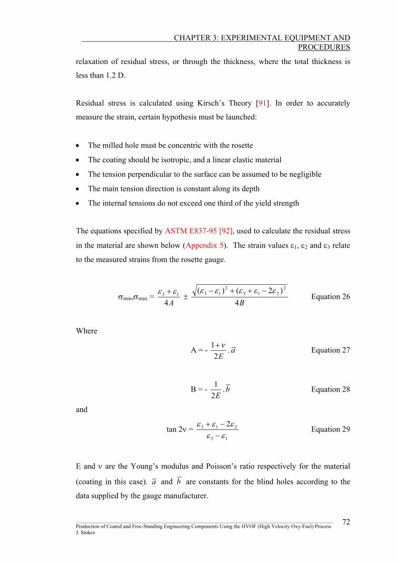
The equations specified by ASTM E837-95 [92], used to calculate the residual stress
in the material are shown below (Appendix 5). The strain values ε1, ε2 and ε3 relate
to the measured strains from the rosette gauge.
σmin,σmax = A4
13 εε + ±
B4)2()( 2
2132
13 εεεεε −++− Equation 26
Where
A = - E2
1 ν+ . a Equation 27
B = - E21 .b Equation 28
and
tan 2ν = 13
21 2εε
3 εεε−
−+ Equation 29
E and ν are the Young’s modulus and Poisson’s ratio respectively for the material
(coating in this case). a and b are constants for the blind holes according to the
data supplied by the gauge manufacturer.
________________________________________________________________________________________________ Production of Coated and Free-Standing Engineering Components Using the HVOF (High Velocity Oxy-Fuel) Process J. Stokes
72
CHAPTER 3: EXPERIMENTAL EQUIPMENT AND
PROCEDURES
3.10 COATING/FORMING THICKNESS MEASUREMENT
Coating/spray-formed thicknesses measurement is an important procedure in the
present research and the equipment utilised depended on whether the thickness is of
the order of micron or of the millimetre range. The following methods have been
used in the current work;
Fischerscope Multi Thickness Measuring Instrument
Dial Gauge Measurement
Microscopic Measurement
Further information on these methods may be found in my additional report [34].
________________________________________________________________________________________________ Production of Coated and Free-Standing Engineering Components Using the HVOF (High Velocity Oxy-Fuel) Process J. Stokes
73
CHAPTER 3: EXPERIMENTAL EQUIPMENT AND
PROCEDURES
3.11 PARAMETER AND PROCESS OPTIMISATION
As spray forming is a development of coating technology, previous research is
therefore very important to the success in forming components. Based on the
research carried out on the HVOF process in the Materials Processing Research
Centre (MPRC), it was felt at the onset of this study that further improvement in
spraying conditions was required. The following text outlines the various parameters
(such as spraying distance control) requiring development, and the procedure
involved in the implementation of that development.
3.11.1 System Automation Control
The linear traverse unit was tested for various traverse speeds and accelerations to
find the optimum parameters to produce quality coatings. Tests were carried out at
traverse speeds suggested by Irons [59], to measure the benefits of keeping pass
thicknesses low and traverse speeds reasonably high. This was carried out by loading
the mount on the traverse unit, with the HVOF Diamond Jet gun and Carbon Dioxide
cooling nozzles. Different velocities were then keyed into the LX program, and the
resultant speed was calculated by timing the travel of the assembly over a distance of
500mm. The optimum speed and acceleration depended on; pass deposition
thickness, spraying temperature, motion of the unit (whether it had a smooth or
jolting motion) and residual stress build up per pass.
Similar to the linear traverse unit, control of the third-axis directional unit was
required to find the optimum height step between each pass to reduced the gaussian
profile of the coating with support from publications such as Figueroa et al. [93] and
Fasching et al. [94]. The optimum speed and displacement depended on; pass
deposition thickness, spraying temperature and the distance between deposit peaks.
________________________________________________________________________________________________ Production of Coated and Free-Standing Engineering Components Using the HVOF (High Velocity Oxy-Fuel) Process J. Stokes
74
CHAPTER 3: EXPERIMENTAL EQUIPMENT AND
PROCEDURES
3.11.2 Young’s Modulus And Poisson’s Ratio Determination
As all of the residual stress determination techniques depend on using the Young’s
modulus and Poisson ratio for the WC-Co material, hence these properties were
established using the ‘Cantilever Bean Method’ as previously described. The
acquired properties were then used in the following sections on residual stress
determination.
3.11.3 Spraying Techniques
In the previous research carried out by Helali [49], where conical thin shaped
components were produced, the DJ spray gun was fixed to a mount at the required
distance from the lathe (onto which the conical shaped substrates were attached), this
enabled the spraying distances to be measured accurately. Following this research
Tan [61] investigated the coating and repair of components by spraying manually (as
a traverse unit did not exist in the facility at the time).
Hence the current research measures residual stress as a function of spraying
technique (manually and controlled). The spraying distance was controlled by
moving the traverse unit in and out a set distance from the substrate material.
Initially strips of stainless steel were used for residual stress measurement using the
Clyne’s Method as described earlier. Based on the spray parameters shown in table
5, thermal spraying was carried out at a spraying distance of 200mm and a powder
feed rate 38gmin-1, while varying the various spraying techniques such as manual
spraying and spraying with automated linear traverse of the gun. Five residual stress
tests were carried out for each spray technique.
Manual spraying was carried out by estimating a spraying distance (from the HVOF
gun from the substrate) of 200mm, as carried out by Tan [61]. Twenty passes of
Diamalloy 2003 WC-Co were applied to each of the five steel strips. The resulting
________________________________________________________________________________________________ Production of Coated and Free-Standing Engineering Components Using the HVOF (High Velocity Oxy-Fuel) Process J. Stokes
75
CHAPTER 3: EXPERIMENTAL EQUIPMENT AND
PROCEDURES
deflection of each strip was measured to calculate the distributed residual stress in
the specimens.
The HVOF gun was then placed onto the linear traverse unit, at an exact spraying
distance of 200mm. Again twenty passes of WC-Co were applied onto five steel
strips, to determine the distributed residual stress build up in each of the coatings.
3.11.4 Forced Cooling
It has been observed [49,61] that whilst spraying time increases, the spraying
temperature increases, therefore interruption to spraying is required, in order to
achieve a constant spray temperature. In those studies compressed air was used to
control the temperature drift, but this only delayed the drift for short periods. As
spraying at a constant temperature is very important, research into another method of
temperature control was needed to increase the efficiency of the DCU system.
Forced cooling helps control the spraying temperature, hence reducing the effect of
mismatch in thermal expansion coefficients between the coating and the substrate,
therefore reducing residual stress build-up.
Carbon dioxide has been reported [62] as a more efficient system of controlling
deposition temperature, hence residual stress was measured as a function of forced
cooling. Spraying was carried out at an exact spraying distance of 200mm (using the
linear traverse unit), with the use of the carbon dioxide cooling system. Twenty
passes of Diamalloy 2003 WC-Co were applied to five steel strips. The resulting
deflection of each strip was measured using the Clyne’s Method to calculate the
distributed residual stress in the specimens.
________________________________________________________________________________________________ Production of Coated and Free-Standing Engineering Components Using the HVOF (High Velocity Oxy-Fuel) Process J. Stokes
76
CHAPTER 3: EXPERIMENTAL EQUIPMENT AND
PROCEDURES
3.11.5 Variation Of Residual Stress With Spraying Distance
Once spraying distance was controlled and forced cooling had been implemented,
determination of the ideal spraying distance for the deposition of WC-Co was
necessary. The method of selection of an ideal distance was by way of residual
stress determination using Clyne’s Method. Mounted steel strips were deposited
with five passes of WC-Co at various distances from 150 to 250mm (at intervals of
10mm). Three tests were carried out at each spraying distance. The stress
distribution at each of these distances, was calculated and the maximum stress within
the coating was displayed graphically as a function of spraying distance.
3.11.6 Variation Of Residual Stress With Powder Feed Rate
Previously in the MPRC, Helali [49] and Tan [61] found two ideal powder feed rates
both 45 and 38gmin-1 respectively, for the WC-Co material. It is expected that the
effect of manual spraying could have led to this difference in results. Hence a
corrected value of powder feed rate needs to be determined. The method of
determination was similar to that in the last section, by way of residual stress
determination. Again mounted steel strips were deposited with five passes of WC-
Co using forced cooling, at various powder feed rates and the maximum residual
stress in the coating was measured for each of the tests. Three tests were carried out
at each feed rate.
3.11.7 Effect Of Residual Stress On Deposit Thickness
Mounted steel strips were pre-heated and then sprayed with WC-Co up to various
thicknesses (by varying the number of passes with the gun), with the use of the linear
traverse unit and the Carbon Dioxide cooling. The deposition was carried out at a
spraying distance of 200mm and a powder feed rate of 38gmin-1, as these were found
to be the optimum parameters in the previous sections. Resulting deflections in the
steel strips were measured and the distributed residual stress was determined through
the coating.
________________________________________________________________________________________________ Production of Coated and Free-Standing Engineering Components Using the HVOF (High Velocity Oxy-Fuel) Process J. Stokes
77
CHAPTER 3: EXPERIMENTAL EQUIPMENT AND
PROCEDURES
3.11.8 Effect Of Residual Stress On Substrate Thickness
WC-Co was deposited onto six 1mm thick substrates. Two deposit thicknesses were
applied (0.2mm and 1mm), with the use of the linear traverse unit at a spraying
distance of 200mm and the carbon dioxide cooling. Resulting deflections in the steel
strips were measured and the distributed residual stress was determined through the
coating.
3.11.9 Effect Of Residual Stress On Sample Length And Width
Mounted steel strips were pre-heated and then sprayed with WC-Co up to various
lengths (100, 80 and 40mm) and widths (20 and 10mm) of samples with the use of
the third-axis unit, and carbon dioxide cooling. The deposition was again carried out
at a spraying temperature of 200mm and a powder feed rate of 38gmin-1. Resulting
deflections in the steel strips, were converted into the maximum coating residual
stress values, to measure the effect the length and width of a coated sample had on
residual stress.
3.11.10 Effect Of Sample Size On Thickness
The length and width of the stainless steel strips were reduced while increasing the
deposit thickness, to produce a maximum deposit thickness. Each sample was pre-
heated and then sprayed with WC-Co at a spraying temperature of 200mm and a
powder feed rate of 38gmin-1. The deflections in the steel strips, were converted into
stress change values (residual stress).
3.11.11 Comparison Of Residual Stress Techniques
Ten samples used to determine the maximum residual stress in the coating by
Clyne’s Method were selected, ranging from a compressive stress of 50 to 200MPa.
Five of these coated samples were metallgraphically polished using the Buehler
________________________________________________________________________________________________ Production of Coated and Free-Standing Engineering Components Using the HVOF (High Velocity Oxy-Fuel) Process J. Stokes
78
CHAPTER 3: EXPERIMENTAL EQUIPMENT AND
PROCEDURES
Motopol 2000 specimen preparation unit (see report [34]) and the residual stress was
measured using the Siemens Diffrac-500 X-ray diffraction system. The residual
stress was measured for the final five coated samples using the RS-200 Milling
Guide (hole-drilling technique). Clyne’s Method of residual stress determination
was compared to the X-ray diffraction and the hole-drilling techniques.
________________________________________________________________________________________________ Production of Coated and Free-Standing Engineering Components Using the HVOF (High Velocity Oxy-Fuel) Process J. Stokes
79
CHAPTER 3: EXPERIMENTAL EQUIPMENT AND
PROCEDURES
3.12 POST TREATMENT TECHNIQUE
3.12.1 Post-Heat Treatment Ten coated steel strips used for residual stress determination were placed into the
Type EF 10/8 Lenton Thermal Design furnace (see report [34]) at 650oC for 80
minutes (and varying temperatures and times after that) in a nitrogen atmosphere to
stress relieve the samples. Each strip had a different measured coating residual stress
result (measured using Clyne’s Method). This experiment was carried out to verify
work carried out by Helali [49], which stated that post heat treating coatings at
650oC for 80 minutes would reduce the sample to a stress free state. The stress was
determined by measuring the resulting deflection after post-heat treatment and
calculating the maximum residual stress in the coating using Clyne’s Method.
Some coatings (two at each temperature) were subjected to further post-heat
treatments at 690, 890 and 1320oC using the Lenton Eurotherm Controller 902P
furnace, for one and two hours. These samples were then ground and polished using
the Buehler Motopol 2000 specimen preparation unit, and examined by the Siemens
Diffrac-500 X-ray diffraction system for elemental and phase changes within the
coatings microstructure as described in the next section.
3.12.2 Shot Peening Method The shot peening method was used to reduce the tensile stress at the surface of the
WC-Co deposit. Silicon carbide shots, 1mm in diameter impacted a 0.2mm thick
deposit on a 0.075mm substrate at 90o for two minutes, using the Ventublast
Mammouth sandblaster. The resultant deflection was converted into a residual
stress distribution through the thickness of the sample. The stress distribution for the
shot peened material was compared to the materials stress distribution before
peening.
________________________________________________________________________________________________ Production of Coated and Free-Standing Engineering Components Using the HVOF (High Velocity Oxy-Fuel) Process J. Stokes
80
CHAPTER 3: EXPERIMENTAL EQUIPMENT AND
PROCEDURES
3.13 PHASE CHARACTERISATION
Materials composed of any element, can be successfully studied with X-ray
Diffraction (XRD) [95]. XRD has already been described as a residual stress
measurement method, but one of its most important uses is in phase identification.
The identification was done by comparing the measured d-spacings in the diffraction
pattern and, to a lesser extent, their integrated intensities with known standards in the
JCPDS (Joint Committee on Powder Diffraction Standards, 1986) Powder
Diffraction software, attached to the Siemens Diffrac-500 X-ray diffraction system.
For specimens containing several phases, the proportion of each phase was
determined from the integrated intensities in the diffraction pattern. Each of the
polished post-heat treated samples in the previous section were examined by the
Siemens Diffrac-500 X-ray diffraction system.
________________________________________________________________________________________________ Production of Coated and Free-Standing Engineering Components Using the HVOF (High Velocity Oxy-Fuel) Process J. Stokes
81
CHAPTER 3: EXPERIMENTAL EQUIPMENT AND
PROCEDURES
3.14 HARDNESS MEASUREMENT
Three methods of measuring the hardness of a material are generally used, such as
static indentation, dynamic indentation and the scratch method. In the static test (test
carried out in the current research) a ball, diamond cone or a pyramid shaped
indenter is forced into the material. Hardness tests carried out at loads of 200
grammes and greater, are known as the Vickers hardness test, whereas the Knoop
test is carried out at lower loads of less than 200 grammes [96].
The hardness of the WC-Co deposit was measured by the Vickers test method using
the Leitz Miniload hardness tester. The scatter of hardness results at loads of 300
grammes, tend to be less than with lower loads [97], hence a 300 gramme load was
applied with a pyramid shaped indenter (figure 30 A). The indentation was observed
using a microscope at a magnitude of 50X and the indentation width was measured
(figure 30 C). The force F applied to cause the indentation is measured, along with
the arithmetic mean of the two separately measured diagonals d (in millimetres),
given in equation 30.
d = 2
''' dd + Equation 30
The calculation of Vickers hardness (values expressed in DPH300) was calculated as
follows [98]:
HV = 1.854 x 10⁶ 2
102.0d
F× Equation 31
Samples must be larger than the minimum distances shown in figure 112 B, there
must be greater than half the mean diagonal length (d) between the edge of the
indentation and the side of the sample. The thickness of the tested material must be
greater than one and a half times the mean diagonal length (d). Various samples were
tested for hardness, to measure the effect of WC-Co deposit thickness and post-heat
treatment, on hardness. Three samples were used to determine the relationship
between thickness and hardness. Hardness results were measured every millimetre
________________________________________________________________________________________________ Production of Coated and Free-Standing Engineering Components Using the HVOF (High Velocity Oxy-Fuel) Process J. Stokes
82
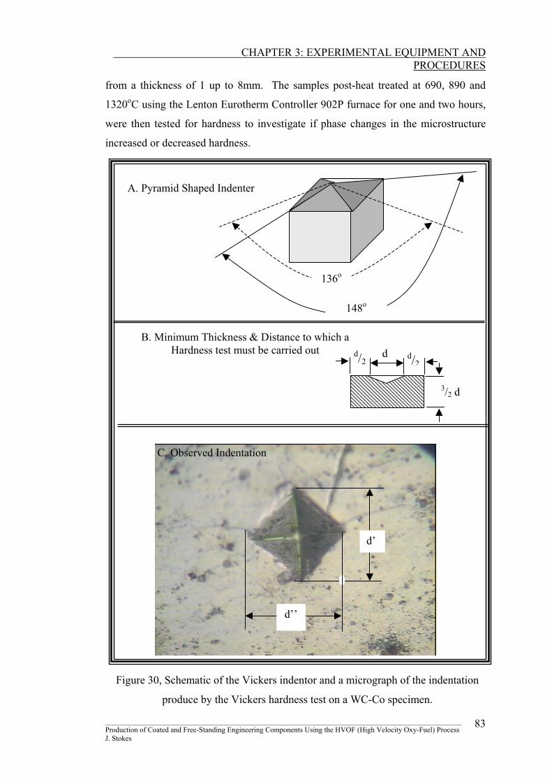
CHAPTER 3: EXPERIMENTAL EQUIPMENT AND
PROCEDURES
from a thickness of 1 up to 8mm. The samples post-heat treated at 690, 890 and
1320oC using the Lenton Eurotherm Controller 902P furnace for one and two hours,
were then tested for hardness to investigate if phase changes in the microstructure
increased or decreased hardness.
________________________________________________________________________________________________
A. Pyramid Shaped Indenter
136o
148o
B. Minimum Thickness & Distance to which a Hardness test must be carried out d d/2
d/2
3/2 d
C. Observed Indentation
d’
d’’
Figure 30, Schematic of the Vickers indentor and a micrograph of the indentation
produce by the Vickers hardness test on a WC-Co specimen.
Production of Coated and Free-Standing Engineering Components Using the HVOF (High Velocity Oxy-Fuel) Process J. Stokes
83
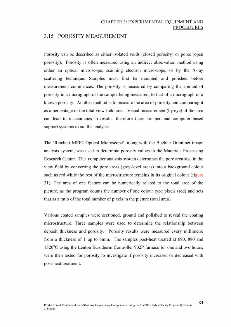
CHAPTER 3: EXPERIMENTAL EQUIPMENT AND
PROCEDURES
3.15 POROSITY MEASUREMENT
Porosity can be described as either isolated voids (closed porosity) or pores (open
porosity). Porosity is often measured using an indirect observation method using
either an optical microscope, scanning electron microscope, or by the X-ray
scattering technique. Samples must first be mounted and polished before
measurement commences. The porosity is measured by comparing the amount of
porosity in a micrograph of the sample being measured, to that of a micrograph of a
known porosity. Another method is to measure the area of porosity and comparing it
as a percentage of the total view field area. Visual measurement (by eye) of the area
can lead to inaccuracies in results, therefore there are personal computer based
support systems to aid the analysis.
The ‘Reichert MEF2 Optical Microscope’, along with the Buehler Omnimet image
analysis system, was used to determine porosity values in the Materials Processing
Research Centre. The computer analysis system determines the pore area size in the
view field by converting the pore areas (grey-level areas) into a background colour
such as red while the rest of the microstructure remains in its original colour (figure
31). The area of one feature can be numerically related to the total area of the
picture, as the program counts the number of one colour type pixels (red) and sets
that as a ratio of the total number of pixels in the picture (total area).
Various coated samples were sectioned, ground and polished to reveal the coating
microstructure. Three samples were used to determine the relationship between
deposit thickness and porosity. Porosity results were measured every millimetre
from a thickness of 1 up to 8mm. The samples post-heat treated at 690, 890 and
1320oC using the Lenton Eurotherm Controller 902P furnace for one and two hours,
were then tested for porosity to investigate if porosity increased or decreased with
post-heat treatment.
________________________________________________________________________________________________ Production of Coated and Free-Standing Engineering Components Using the HVOF (High Velocity Oxy-Fuel) Process J. Stokes
84
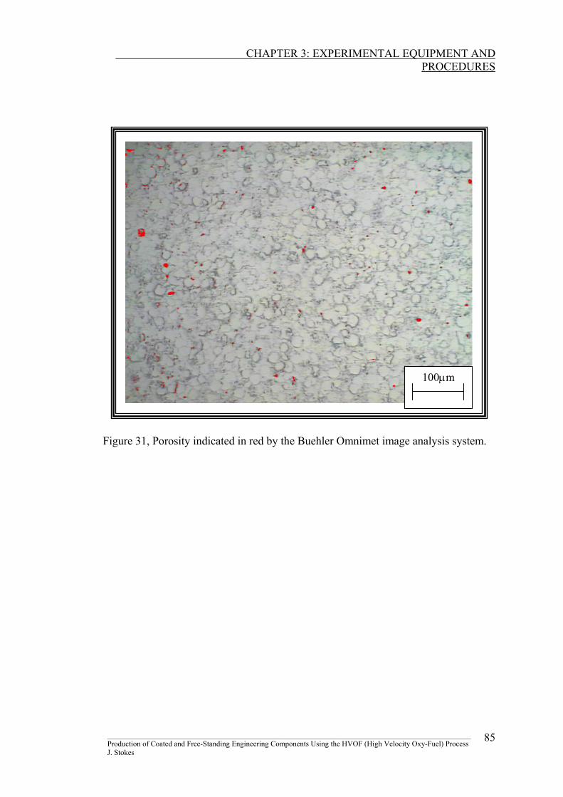
CHAPTER 3: EXPERIMENTAL EQUIPMENT AND
PROCEDURES
100µm
Figure 31, Porosity indicated in red by the Buehler Omnimet image analysis system.
________________________________________________________________________________________________ Production of Coated and Free-Standing Engineering Components Using the HVOF (High Velocity Oxy-Fuel) Process J. Stokes
85
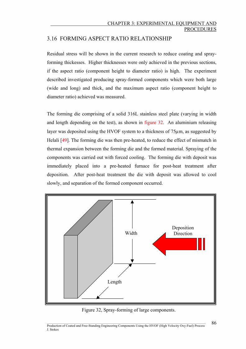
CHAPTER 3: EXPERIMENTAL EQUIPMENT AND
PROCEDURES
3.16 FORMING ASPECT RATIO RELATIONSHIP Residual stress will be shown in the current research to reduce coating and spray-
forming thickesses. Higher thicknesses were only achieved in the previous sections,
if the aspect ratio (component height to diameter ratio) is high. The experiment
described investigated producing spray-formed components which were both large
(wide and long) and thick, and the maximum aspect ratio (component height to
diameter ratio) achieved was measured.
The forming die comprising of a solid 316L stainless steel plate (varying in width
and length depending on the test), as shown in figure 32. An aluminium releasing
layer was deposited using the HVOF system to a thickness of 75µm, as suggested by
Helali [49]. The forming die was then pre-heated, to reduce the effect of mismatch in
thermal expansion between the forming die and the formed material. Spraying of the
components was carried out with forced cooling. The forming die with deposit was
immediately placed into a pre-heated furnace for post-heat treatment after
deposition. After post-heat treatment the die with deposit was allowed to cool
slowly, and separation of the formed component occurred.
Deposition Direction Width
Length
Figure 32, Spray-forming of large components.
________________________________________________________________________________________________ Production of Coated and Free-Standing Engineering Components Using the HVOF (High Velocity Oxy-Fuel) Process J. Stokes
86
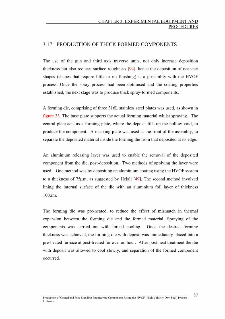
CHAPTER 3: EXPERIMENTAL EQUIPMENT AND
PROCEDURES
3.17 PRODUCTION OF THICK FORMED COMPONENTS
The use of the gun and third axis traverse units, not only increase deposition
thickness but also reduces surface roughness [94], hence the deposition of near-net
shapes (shapes that require little or no finishing) is a possibility with the HVOF
process. Once the spray process had been optimised and the coating properties
established, the next stage was to produce thick spray-formed components.
A forming die, comprising of three 316L stainless steel plates was used, as shown in
figure 33. The base plate supports the actual forming material whilst spraying. The
central plate acts as a forming plate, where the deposit fills up the hollow void, to
produce the component. A masking plate was used at the front of the assembly, to
separate the deposited material inside the forming die from that deposited at its edge.
An aluminium releasing layer was used to enable the removal of the deposited
component from the die, post-deposition. Two methods of applying the layer were
used. One method was by depositing an aluminium coating using the HVOF system
to a thickness of 75µm, as suggested by Helali [49]. The second method involved
lining the internal surface of the die with an aluminium foil layer of thickness
100µm.
The forming die was pre-heated, to reduce the effect of mismatch in thermal
expansion between the forming die and the formed material. Spraying of the
components was carried out with forced cooling. Once the desired forming
thickness was achieved, the forming die with deposit was immediately placed into a
pre-heated furnace at post-treated for over an hour. After post-heat treatment the die
with deposit was allowed to cool slowly, and separation of the formed component
occurred.
________________________________________________________________________________________________ Production of Coated and Free-Standing Engineering Components Using the HVOF (High Velocity Oxy-Fuel) Process J. Stokes
87
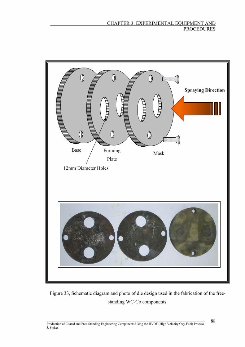
CHAPTER 3: EXPERIMENTAL EQUIPMENT AND
PROCEDURES
12mm Diameter Holes
Mask Forming
Plate
Base
Spraying Direction
Figure 33, Schematic diagram and photo of die design used in the fabrication of the free-
standing WC-Co components.
________________________________________________________________________________________________ Production of Coated and Free-Standing Engineering Components Using the HVOF (High Velocity Oxy-Fuel) Process J. Stokes
88
CHAPTER 3: EXPERIMENTAL EQUIPMENT AND
PROCEDURES
3.18 PRODUCTION OF A TENSILE SPECIMEN Previously the ‘Cantilever Test’ was described as the method used to determining the
Young’s modulus of the WC-Co material. The test is acceptable however the
influence of the attached substrate was questioned, as the substrate properties may
influence the measurement of the deposits stiffness. The following experiment
describes the production of a free-standing WC-Co tensile specimen.
A forming die assembly, similar to that for the cylindrical components was designed
to produce tungsten carbide cobalt spray-formed tensile specimens, based on the
dimensions required for sinter-formed specimens, outlined in ASTM E8M-96 [74],
ASTM B823 [99] and MPIF [100], as shown in Appendix 6.
The forming die comprised of three 316L stainless steel plates, as shown in figure
34. The base plate supported the actual forming material whilst spraying. The
central plate acted as the forming plate, where the deposit fills up the hollow void, to
produce the specimen. A masking plate was used just as in the previous experiment
at the front of the assembly. An aluminium releasing layer (lining the internal
surface of the die with an aluminium foil layer of thickness 100µm) was used to
enable the removal of the deposited component from the die, post-deposition. The
forming die was pre-heated and spraying of the components was carried out with
forced cooling. Once the desired forming thickness was achieved, the forming die
with deposit was immediately placed into a pre-heated furnace at 675oC for over an
hour. After post-heat treatment the die with deposit was allowed to cool slowly, and
separation of the formed component occurred. The samples were then tensile tested
with the Hounsfield H20K-W tension/compression tester (using a 20kN load cell), to
measure the tungsten carbide-cobalt stiffness. The rate of displacement was set at
the machines minimum 0.54 mm.min-1. The data was transferred to an Excel
spreadsheet where the stress-strain relationship was graphically presented. From the
stress-strain graph a Young’s modulus for WC-Co was determined.
________________________________________________________________________________________________ Production of Coated and Free-Standing Engineering Components Using the HVOF (High Velocity Oxy-Fuel) Process J. Stokes
89
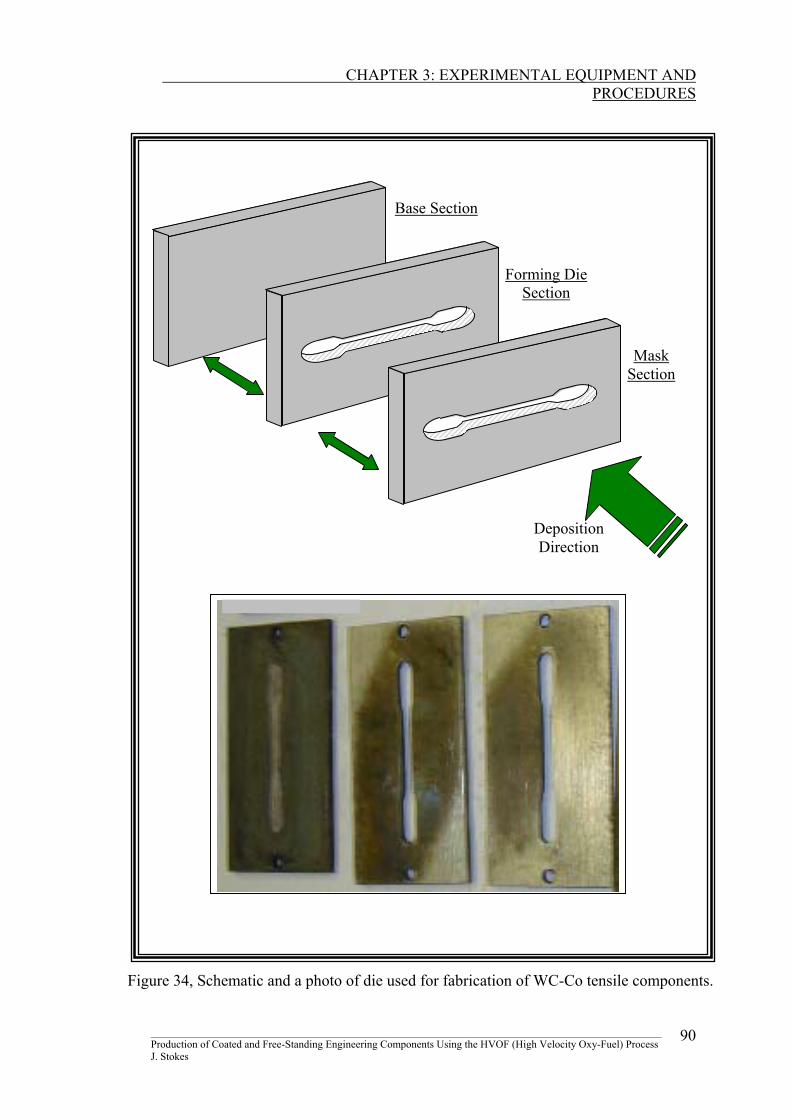
CHAPTER 3: EXPERIMENTAL EQUIPMENT AND
PROCEDURES
Production of Coated and Free-Standing Engineering Components Using the HVOF (High Velocity Oxy-Fuel) Process J. Stokes
________________________________________________________________________________________________ 90
Base Section
Forming Die
Section
Mask
Section
Deposition Direction
Figure 34, Schematic and a photo of die used for fabrication of WC-Co tensile components.