Embed Size (px)
Citation preview
Experimental Effective Shape Controlof a Powered Transfemoral Prosthesis
Robert D. Gregg, Tommaso Lenzi, Nicholas P. Fey, Levi J. Hargrove, and Jonathon W. Sensinger
Abstract— This paper presents the design and experimentalimplementation of a novel feedback control strategy thatregulates effective shape on a powered transfemoral prosthesis.The human effective shape is the effective geometry to which thebiological leg conforms—through movement of ground reactionforces and leg joints—during the stance period of gait. Able-bodied humans regulate effective shapes to be invariant acrossconditions such as heel height, walking speed, and body weight,so this measure has proven to be a very useful tool for thealignment and design of passive prostheses. However, leg jointsmust be actively controlled to assume different effective shapesthat are unique to tasks such as standing, walking, and stairclimbing. Using our previous simulation studies as a startingpoint, we model and control the effective shape as a virtualkinematic constraint on the powered Vanderbilt prosthetic legwith a custom instrumented foot. An able-bodied subject used aby-pass adapter to walk on the controlled leg over ground andover a treadmill. These preliminary experiments demonstrate,for the first time, that effective shape (or virtual constraints ingeneral) can be used to control a powered prosthetic leg.
I. INTRODUCTION
The effective shape of the human leg during locomotortasks (called the rollover shape during walking) has beenstudied for over a decade [1] and has proven to be a veryuseful measure for gait analysis and prosthesis alignment[2], [3]. The effective shape is the trajectory of the centerof pressure (COP)—the point on the plantar sole of the footwhere the cumulative reaction force is imparted against theground—mapped into a moving reference frame attached tothe stance leg. For a rigid object, e.g., a metal wheel, theeffective shape is its actual geometry. However, the effectiveshape of an object that includes a compliant or controllablejoint—such as a human or prosthetic ankle—is variable andcan be regulated, for example, within the local coordinateframe of the shank or thigh.
Able-bodied humans appear to regulate their effectiveshape to remain invariant across many conditions, includingheel height [3], walking speed [4], and body weight[1]. This suggests the effective shape is fundamental tohuman locomotor control and could be useful for designingprosthetic legs that are more adaptable than conventional
Asterisk indicates corresponding author.R.D. Gregg* is with the Departments of Mechanical Engineering and
Bioengineering, University of Texas at Dallas, Richardson, TX [email protected]
T. Lenzi, N.P. Fey, L.J. Hargrove, and J.W. Sensinger are with theCenter for Bionic Medicine, Rehabilitation Institute of Chicago andthe Departments of Physical Medicine & Rehabilitation and MechanicalEngineering, Northwestern University, Chicago, IL 60611.
This research was supported by USAMRAA grant W81XWH-09-2-0020.Robert De Moss Gregg, IV, Ph.D., holds a Career Award at the ScientificInterface from the Burroughs Wellcome Fund.
prostheses, which cause discomfort and instability as theseconditions vary. A passive below-knee prosthesis calledthe ‘Shape&Roll’ foot was designed to provide a naturaleffective shape in [5]. However, this device can only betuned to one task at a time, whereas humans employ effectiveshapes unique to different tasks such as standing, walking,and stair climbing. For example, the shape curvature changessubstantially between walking and stationary standing [6],and upstairs climbing requires a completely differentgeometry [7] with positive mechanical work.
The recent development of powered prosthetic legs (e.g.,[8]–[12]) provides an opportunity to implement the effectiveshapes for a wide variety of tasks including those thatrequire positive work contribution. A general model of theseshapes could enable these prostheses to control differenttasks with one unifying control strategy, in contrast tocurrent task-specific approaches that depend on pre-definedreference trajectories [8], [12]. Because the effective shapecharacterizes the entire stance period of gait, this controlapproach could also improve the clinical viability of poweredlegs by reducing the time needed to tune control parameterscompared to strategies that discretize the stance period intomultiple control models [9]–[11].
For the purpose of designing this unifying controlstrategy, we look to recent work on autonomous bipedalrobots, which can walk, run, and climb stairs using onecontrol framework [13], [14]. This nonlinear feedbackcontrol approach produces joint torques to virtually enforcekinematic constraints [13]–[15], which define desired jointpatterns as functions of a mechanical phase variable (e.g.,the stance leg angle or hip position). In other words,a monotonic (e.g., strictly increasing) variable serves asa unique representation of the gait cycle phase, whichparameterizes a nonlinear control model to create appropriatephase-specific behaviors. Because the COP is a monotonicvariable [16], the effective shape can similarly be modeledas a phase-based kinematic constraint.
We recently demonstrated this principle in simulation bycontrolling the effective shape of an ankle prosthesis [16] anda knee-ankle prosthesis [17] during a walking task. Becausethe thigh-based effective shape depends on both the knee andankle, this strategy coordinated the control of both joints toproduce human-like patterns in [17]. This coordinated controlapproach also resulted in robustness to small perturbations.By treating the COP as a phase variable and the effectiveshape as a general virtual constraint for the leg joints, thisnovel approach has the potential to make prosthetic legsmore adaptable, robust, and easily tuned than with current
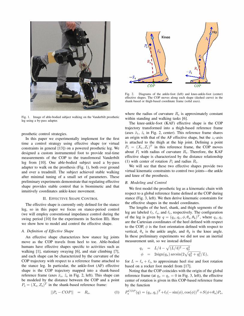
Fig. 1. Image of able-bodied subject walking on the Vanderbilt prostheticleg using a by-pass adapter.
prosthetic control strategies.In this paper we experimentally implement for the first
time a control strategy using effective shape (or virtualconstraints in general [13]) on a powered prosthetic leg. Wedesigned a custom instrumented foot to provide real-timemeasurements of the COP to the transfemoral Vanderbiltleg from [10]. One able-bodied subject used a by-passadapter to walk on the prosthesis (Fig. 1), both over groundand over a treadmill. The subject achieved stable walkingafter minimal tuning of a small set of parameters. Thesepreliminary experiments demonstrate that regulating effectiveshape provides stable control that is biomimetic and thatintuitively coordinates ankle-knee movement.
II. EFFECTIVE SHAPE CONTROL
The effective shape is currently only defined for the stanceleg, so in this paper we focus on stance-period control(we will employ conventional impedance control during theswing period [10] for the experiments in Section III). Herewe show how to model and control the effective shape.
A. Definition of Effective Shape
An effective shape characterizes how stance leg jointsmove as the COP travels from heel to toe. Able-bodiedhumans have effective shapes specific to activities such aswalking [1], stationary swaying [6], and stair climbing [7],and each shape can be characterized by the curvature of theCOP trajectory with respect to a reference frame attached tothe stance leg. In particular, the ankle-foot (AF) effectiveshape is the COP trajectory mapped into a shank-basedreference frame (axes xs, zs in Fig. 2, left). This shape canbe modeled by the distance between the COP and a pointPs = (Xs, Zs)
T in the shank-based reference frame:
||Ps − COP || = Rs, (1)
Fig. 2. Diagrams of the ankle-foot (left) and knee-ankle-foot (center)effective shapes. The COP moves along each shape (dashed curve) in theshank-based or thigh-based coordinate frame (solid axes).
where the radius of curvature Rs is approximately constantwithin standing and walking tasks [6].
The knee-ankle-foot (KAF) effective shape is the COPtrajectory transformed into a thigh-based reference frame(axes xt, zt in Fig. 2, center). This reference frame sharesan origin with that of the AF effective shape, but the zt-axisis attached to the thigh at the hip joint. Defining a pointPt = (Xt, Zt)
T in this reference frame, the COP movesabout Pt with radius of curvature Rt. Therefore, the KAFeffective shape is characterized by the distance relationship(1) with center of rotation Pt and radius Rt.
We will see that these two effective shapes provide twovirtual kinematic constraints to control two joints—the ankleand knee of the prosthesis.
B. Modeling and Control
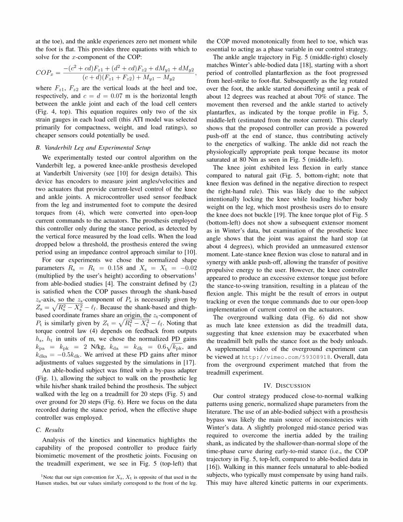
We first model the prosthetic leg as a kinematic chain withrespect to a global reference frame defined at the COP duringstance (Fig. 3, left). We then derive kinematic constraints forthe effective shapes in the model coordinates.
The lengths of the heel, shank, and thigh segments of theleg are labeled `f , `s, and `t, respectively. The configurationof the leg is given by q = (qx, qz, φ, θa, θk)
T , where qx, qzare the Cartesian coordinates of the heel defined with respectto the COP, φ is the foot orientation defined with respect tovertical, θa is the ankle angle, and θk is the knee angle.In these preliminary experiments we did not use an inertialmeasurement unit, so we instead defined
qz = L/4−√
(L/4)2 − q2xφ = 2sign(qx) arcsin(2
√q2x + q2z/L),
for L = `s + `t, to approximate heel rise and foot rotationbased on a rocker foot model from [17].
Noting that the COP coincides with the origin of the globalreference frame (at qx = qz = 0 in Fig. 3, left), the effectivecenter of rotation is given in this COP-based reference frameby the function
PCOPs (q) = (qx, qz)
T+`f(− sin(φ), cos(φ))T+S(φ+θa)Ps,
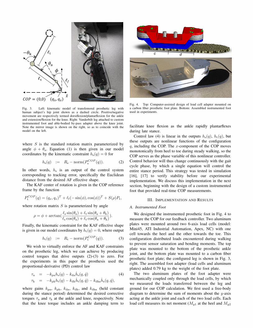
Fig. 3. Left: kinematic model of transfemoral prosthetic leg withhuman subject’s hip joint shown as a dashed circle. Positive/negativemovement are respectively termed dorsiflexion/plantarflexion for the ankleand extension/flexion for the knee. Right: Vanderbilt leg attached to custominstrumented foot and able-bodied by-pass adapter above the knee joint.Note the mirror image is shown on the right, so as to coincide with themodel on the left.
where S is the standard rotation matrix parameterized byangle φ + θa. Equation (1) is then given in our modelcoordinates by the kinematic constraint hs(q) = 0 for
hs(q) := Rs − norm(PCOPs (q)). (2)
In other words, hs is an output of the control systemcorresponding to tracking error, specifically the Euclideandistance from the desired AF effective shape.
The KAF center of rotation is given in the COP referenceframe by the function
PCOPt (q) = (qx, qz)
T + `f(− sin(φ), cos(φ))T + S(ρ)Pt,
where rotation matrix S is parameterized by angle
ρ = φ+ arctan(`s sin(θa) + `t sin(θa + θk)
`s cos(θa) + `t cos(θa + θk)).
Finally, the kinematic constraint for the KAF effective shapeis given in our model coordinates by ht(q) = 0, where output
ht(q) := Rt − norm(PCOPt (q)). (3)
We wish to virtually enforce the AF and KAF constraintson the prosthetic leg, which we can achieve by producingcontrol torques that drive outputs (2)-(3) to zero. Forthe experiments in this paper the prosthesis used theproportional-derivative (PD) control law
τa = −kpahs(q)− kdahs(q, q) (4)
τk = −kpkht(q)− kdkht(q, q)− kdkahs(q, q),
where gains kpa, kpk, kda, kdk, and kdka (held constantduring the stance period) determined the desired correctivetorques τa and τk at the ankle and knee, respectively. Notethat the knee torque includes an ankle damping term to
c d
Fig. 4. Top: Computer-assisted design of load cell adapter mounted ona carbon fiber prosthetic foot plate. Bottom: Assembled instrumented footused in experiments.
facilitate knee flexion as the ankle rapidly plantarflexesduring late stance.
Control law (4) is linear in the outputs hs(q), ht(q), butthese outputs are nonlinear functions of the configurationq, including the COP. The x-component of the COP movesmonotonically from heel to toe during steady walking, so theCOP serves as the phase variable of this nonlinear controller.Control behavior will thus change continuously with the gaitcycle phase, by which a single equation will control theentire stance period. This strategy was tested in simulation[16], [17] to verify stability before our experimentalimplementation. We discuss this implementation in the nextsection, beginning with the design of a custom instrumentedfoot that provided real-time COP measurements.
III. IMPLEMENTATION AND RESULTS
A. Instrumented Foot
We designed the instrumented prosthetic foot in Fig. 4 tomeasure the COP for our feedback controller. Two aluminumplates were mounted around two 6-axis load cells (model:Mini45, ATI Industrial Automation, Apex, NC) with onecell towards the heel and the other towards the toe. Thisconfiguration distributed loads encountered during walkingto prevent sensor saturation and bending moments. The topplate was mounted to the bottom of the prosthetic anklejoint, and the bottom plate was mounted to a carbon fiberprosthetic foot plate; the configured leg is shown in Fig. 3,right. The assembled foot adapter (load cells and aluminumplates) added 0.79 kg to the weight of the foot plate.
The two aluminum plates of the foot adapter weremechanically coupled only through the load cells, by whichwe measured the loads transferred between the leg andground for our COP calculation. We first used a free-bodydiagram to determine the sum of moments about the y-axisacting at the ankle joint and each of the two load cells. Eachload cell measures its net moment (My1 at the heel and My2
at the toe), and the ankle experiences zero net moment whilethe foot is flat. This provides three equations with which tosolve for the x-component of the COP:
COPx =−(c2 + cd)Fz1 + (d2 + cd)Fz2 + dMy1 + dMy2
(c+ d)(Fz1 + Fz2) +My1 −My2,
where Fz1, Fz2 are the vertical loads at the heel and toe,respectively, and c = d = 0.07 m is the horizontal lengthbetween the ankle joint and each of the load cell centers(Fig. 4, top). This equation requires only two of the sixstrain gauges in each load cell (this ATI model was selectedprimarily for compactness, weight, and load ratings), socheaper sensors could potentially be used.
B. Vanderbilt Leg and Experimental Setup
We experimentally tested our control algorithm on theVanderbilt leg, a powered knee-ankle prosthesis developedat Vanderbilt University (see [10] for design details). Thisdevice has encoders to measure joint angles/velocities andtwo actuators that provide current-level control of the kneeand ankle joints. A microcontroller used sensor feedbackfrom the leg and instrumented foot to compute the desiredtorques from (4), which were converted into open-loopcurrent commands to the actuators. The prosthesis employedthis controller only during the stance period, as detected bythe vertical force measured by the load cells. When the loaddropped below a threshold, the prosthesis entered the swingperiod using an impedance control approach similar to [10].
For our experiments we chose the normalized shapeparameters Rs = Rt = 0.158 and Xs = Xt = −0.02(multiplied by the user’s height) according to observations1
from able-bodied studies [4]. The constraint defined by (2)is satisfied when the COP passes through the shank-basedzs-axis, so the zs-component of Ps is necessarily given byZs =
√R2
s −X2s − `f . Because the shank-based and thigh-
based coordinate frames share an origin, the zt-component ofPt is similarly given by Zt =
√R2
t −X2t − `f . Noting that
torque control law (4) depends on feedback from outputshs, ht in units of m, we chose the normalized PD gainskpa = kpk = 2 N/kg, kda = kdk = 0.6
√kpk, and
kdka = −0.5kdk. We arrived at these PD gains after minoradjustments of values suggested by the simulations in [17].
An able-bodied subject was fitted with a by-pass adapter(Fig. 1), allowing the subject to walk on the prosthetic legwhile his/her shank trailed behind the prosthesis. The subjectwalked with the leg on a treadmill for 20 steps (Fig. 5) andover ground for 20 steps (Fig. 6). Here we focus on the datarecorded during the stance period, when the effective shapecontroller was employed.
C. Results
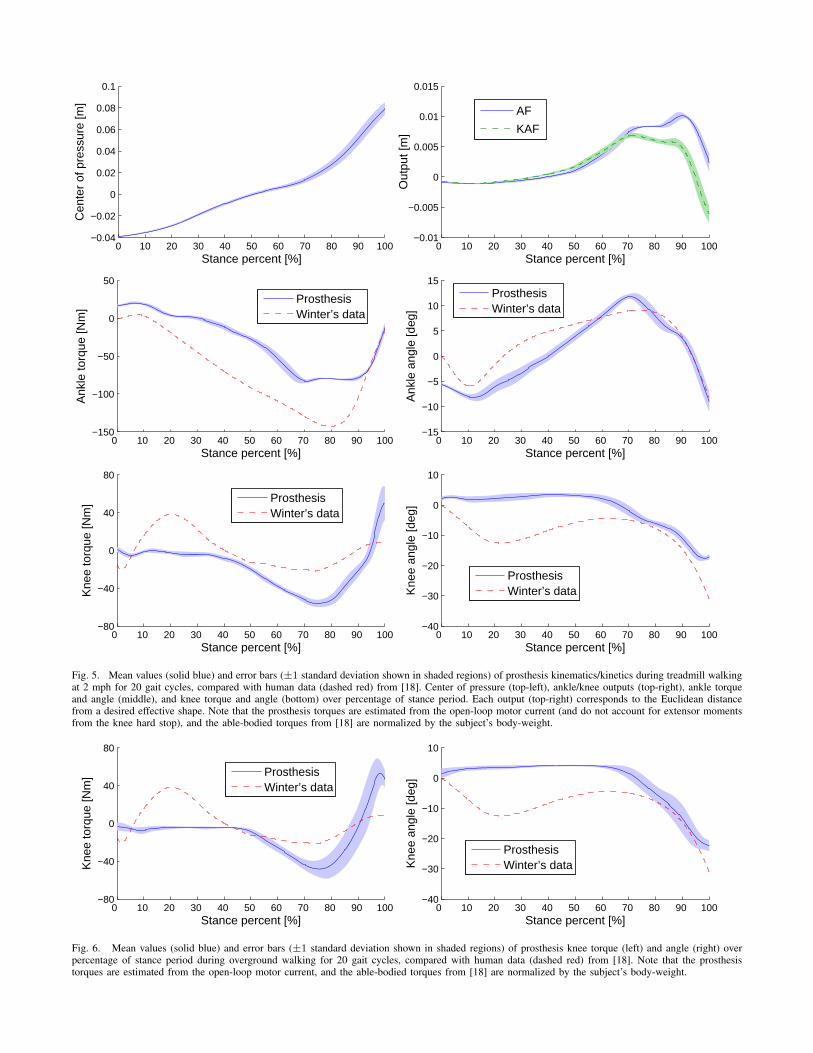
Analysis of the kinetics and kinematics highlights thecapability of the proposed controller to produce fairlybiomimetic movement of the prosthetic joints. Focusing onthe treadmill experiment, we see in Fig. 5 (top-left) that
1Note that our sign convention for Xs, Xt is opposite of that used in theHansen studies, but our values similarly correspond to the front of the leg.
the COP moved monotonically from heel to toe, which wasessential to acting as a phase variable in our control strategy.
The ankle angle trajectory in Fig. 5 (middle-right) closelymatches Winter’s able-bodied data [18], starting with a shortperiod of controlled plantarflexion as the foot progressedfrom heel-strike to foot-flat. Subsequently as the leg rotatedover the foot, the ankle started dorsiflexing until a peak ofabout 12 degrees was reached at about 70% of stance. Themovement then reversed and the ankle started to activelyplantarflex, as indicated by the torque profile in Fig. 5,middle-left (estimated from the motor current). This clearlyshows that the proposed controller can provide a poweredpush-off at the end of stance, thus contributing activelyto the energetics of walking. The ankle did not reach thephysiologically appropriate peak torque because its motorsaturated at 80 Nm as seen in Fig. 5 (middle-left).
The knee joint exhibited less flexion in early stancecompared to natural gait (Fig. 5, bottom-right; note thatknee flexion was defined in the negative direction to respectthe right-hand rule). This was likely due to the subjectintentionally locking the knee while loading his/her bodyweight on the leg, which most prosthesis users do to ensurethe knee does not buckle [19]. The knee torque plot of Fig. 5(bottom-left) does not show a subsequent extensor momentas in Winter’s data, but examination of the prosthetic kneeangle shows that the joint was against the hard stop (atabout 4 degrees), which provided an unmeasured extensormoment. Late-stance knee flexion was close to natural and insynergy with ankle push-off, allowing the transfer of positivepropulsive energy to the user. However, the knee controllerappeared to produce an excessive extensor torque just beforethe stance-to-swing transition, resulting in a plateau of theflexion angle. This might be the result of errors in outputtracking or even the torque commands due to our open-loopimplementation of current control on the actuators.
The overground walking data (Fig. 6) did not showas much late knee extension as did the treadmill data,suggesting that knee extension may be exacerbated whenthe treadmill belt pulls the stance foot as the body unloads.A supplemental video of the overground experiment canbe viewed at http://vimeo.com/59308918. Overall, datafrom the overground experiment matched that from thetreadmill experiment.
IV. DISCUSSION
Our control strategy produced close-to-normal walkingpatterns using generic, normalized shape parameters from theliterature. The use of an able-bodied subject with a prosthesisbypass was likely the main source of inconsistencies withWinter’s data. A slightly prolonged mid-stance period wasrequired to overcome the inertia added by the trailingshank, as indicated by the shallower-than-normal slope of thetime-phase curve during early-to-mid stance (i.e., the COPtrajectory in Fig. 5, top-left, compared to able-bodied data in[16]). Walking in this manner feels unnatural to able-bodiedsubjects, who typically must compensate by using hand rails.This may have altered kinetic patterns in our experiments.
0 10 20 30 40 50 60 70 80 90 100−0.04
−0.02
0
0.02
0.04
0.06
0.08
0.1
Stance percent [%]
Cen
ter
of p
ress
ure
[m]
0 10 20 30 40 50 60 70 80 90 100−0.01
−0.005
0
0.005
0.01
0.015
Stance percent [%]
Out
put [
m]
AF
KAF
0 10 20 30 40 50 60 70 80 90 100−150
−100
−50
0
50
Stance percent [%]
Ank
le to
rque
[Nm
]
ProsthesisWinter’s data
0 10 20 30 40 50 60 70 80 90 100−15
−10
−5
0
5
10
15
Stance percent [%]
Ank
le a
ngle
[deg
]
ProsthesisWinter’s data
0 10 20 30 40 50 60 70 80 90 100−80
−40
0
40
80
Stance percent [%]
Kne
e to
rque
[Nm
]
ProsthesisWinter’s data
0 10 20 30 40 50 60 70 80 90 100−40
−30
−20
−10
0
10
Stance percent [%]
Kne
e an
gle
[deg
]
ProsthesisWinter’s data
Fig. 5. Mean values (solid blue) and error bars (±1 standard deviation shown in shaded regions) of prosthesis kinematics/kinetics during treadmill walkingat 2 mph for 20 gait cycles, compared with human data (dashed red) from [18]. Center of pressure (top-left), ankle/knee outputs (top-right), ankle torqueand angle (middle), and knee torque and angle (bottom) over percentage of stance period. Each output (top-right) corresponds to the Euclidean distancefrom a desired effective shape. Note that the prosthesis torques are estimated from the open-loop motor current (and do not account for extensor momentsfrom the knee hard stop), and the able-bodied torques from [18] are normalized by the subject’s body-weight.
0 10 20 30 40 50 60 70 80 90 100−80
−40
0
40
80
Stance percent [%]
Kne
e to
rque
[Nm
]
ProsthesisWinter’s data
0 10 20 30 40 50 60 70 80 90 100−40
−30
−20
−10
0
10
Stance percent [%]
Kne
e an
gle
[deg
]
ProsthesisWinter’s data
Fig. 6. Mean values (solid blue) and error bars (±1 standard deviation shown in shaded regions) of prosthesis knee torque (left) and angle (right) overpercentage of stance period during overground walking for 20 gait cycles, compared with human data (dashed red) from [18]. Note that the prosthesistorques are estimated from the open-loop motor current, and the able-bodied torques from [18] are normalized by the subject’s body-weight.
These problems will likely be avoided in future studies byrecruiting transfemoral amputee subjects.
Some inconsistencies were also caused by limitations incontrol authority. Tracking error from the desired effectiveshapes (Fig. 5, top-right) grew through the step due to 1)ankle actuator saturation, 2) low-gain PD control at the jointlevel, and 3) open-loop current control at the motor level.We were unable to reliably increase the PD gains furtherbecause the existing control architecture limited us to a 100Hz sampling frequency for joint-level control. In additionto implementing a faster control loop, tracking error couldbe greatly reduced in the future by using a more powerfulankle motor, a more exact control method such as input-output linearization [16], [17], and a closed torque-controlloop at the motor level.
Despite these remaining challenges, the control frameworkproposed in this paper could potentially improve the clinicalviability of powered transfemoral prostheses. The knee-anklestrategy used only five independent control parameters (Rs =Rt, Xs = Xt, kpa = kpk, kda = kdk, kdka) for theentire stance period, whereas other control approaches havemany more parameters during stance (e.g., 18 for sequentialimpedance control [10], 14 for one joint’s muscle model[11], or an entire look-up table for tracking human data[12]). The effective radii Rs, Rt and rotational centers Xs,Xt are defined by simple fractions of the user’s height [4],offering a straight-forward tuning procedure for clinicians.The rotational centers determine the amount of flexion in theankle and knee joints, respectively, so these characteristicscan be systematically adjusted to the user’s preference.
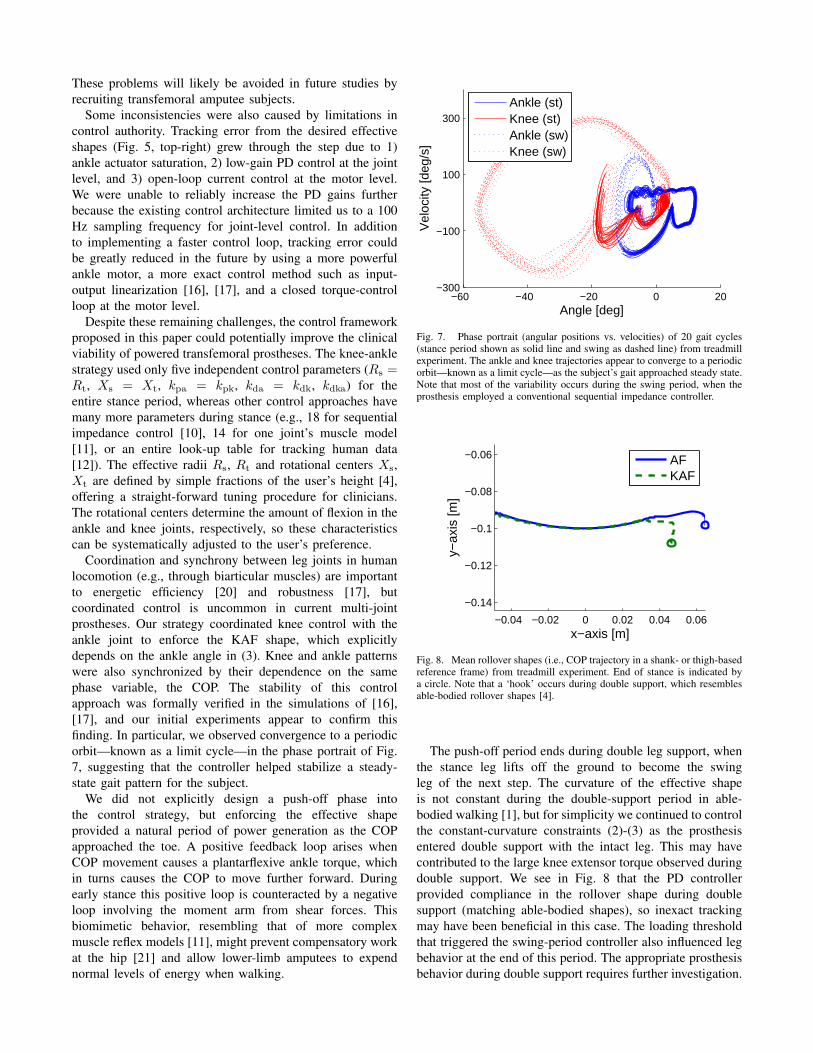
Coordination and synchrony between leg joints in humanlocomotion (e.g., through biarticular muscles) are importantto energetic efficiency [20] and robustness [17], butcoordinated control is uncommon in current multi-jointprostheses. Our strategy coordinated knee control with theankle joint to enforce the KAF shape, which explicitlydepends on the ankle angle in (3). Knee and ankle patternswere also synchronized by their dependence on the samephase variable, the COP. The stability of this controlapproach was formally verified in the simulations of [16],[17], and our initial experiments appear to confirm thisfinding. In particular, we observed convergence to a periodicorbit—known as a limit cycle—in the phase portrait of Fig.7, suggesting that the controller helped stabilize a steady-state gait pattern for the subject.
We did not explicitly design a push-off phase intothe control strategy, but enforcing the effective shapeprovided a natural period of power generation as the COPapproached the toe. A positive feedback loop arises whenCOP movement causes a plantarflexive ankle torque, whichin turns causes the COP to move further forward. Duringearly stance this positive loop is counteracted by a negativeloop involving the moment arm from shear forces. Thisbiomimetic behavior, resembling that of more complexmuscle reflex models [11], might prevent compensatory workat the hip [21] and allow lower-limb amputees to expendnormal levels of energy when walking.
−60 −40 −20 0 20−300
−100
100
300
Angle [deg]
Vel
ocity
[deg
/s]
Ankle (st)Knee (st)Ankle (sw)Knee (sw)
Fig. 7. Phase portrait (angular positions vs. velocities) of 20 gait cycles(stance period shown as solid line and swing as dashed line) from treadmillexperiment. The ankle and knee trajectories appear to converge to a periodicorbit—known as a limit cycle—as the subject’s gait approached steady state.Note that most of the variability occurs during the swing period, when theprosthesis employed a conventional sequential impedance controller.
−0.04 −0.02 0 0.02 0.04 0.06
−0.14
−0.12
−0.1
−0.08
−0.06
x−axis [m]
y−ax
is [m
]
AFKAF
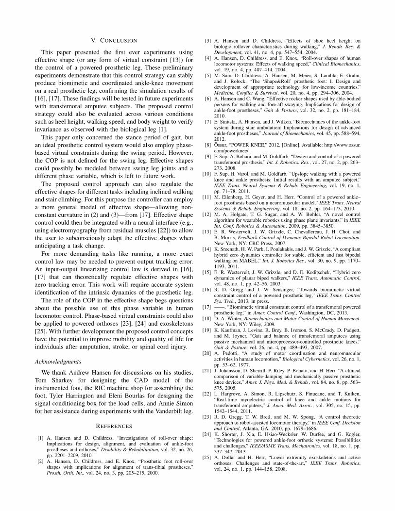
Fig. 8. Mean rollover shapes (i.e., COP trajectory in a shank- or thigh-basedreference frame) from treadmill experiment. End of stance is indicated bya circle. Note that a ‘hook’ occurs during double support, which resemblesable-bodied rollover shapes [4].
The push-off period ends during double leg support, whenthe stance leg lifts off the ground to become the swingleg of the next step. The curvature of the effective shapeis not constant during the double-support period in able-bodied walking [1], but for simplicity we continued to controlthe constant-curvature constraints (2)-(3) as the prosthesisentered double support with the intact leg. This may havecontributed to the large knee extensor torque observed duringdouble support. We see in Fig. 8 that the PD controllerprovided compliance in the rollover shape during doublesupport (matching able-bodied shapes), so inexact trackingmay have been beneficial in this case. The loading thresholdthat triggered the swing-period controller also influenced legbehavior at the end of this period. The appropriate prosthesisbehavior during double support requires further investigation.
V. CONCLUSION
This paper presented the first ever experiments usingeffective shape (or any form of virtual constraint [13]) forthe control of a powered prosthetic leg. These preliminaryexperiments demonstrate that this control strategy can stablyproduce biomimetic and coordinated ankle-knee movementon a real prosthetic leg, confirming the simulation results of[16], [17]. These findings will be tested in future experimentswith transfemoral amputee subjects. The proposed controlstrategy could also be evaluated across various conditionssuch as heel height, walking speed, and body weight to verifyinvariance as observed with the biological leg [1].
This paper only concerned the stance period of gait, butan ideal prosthetic control system would also employ phase-based virtual constraints during the swing period. However,the COP is not defined for the swing leg. Effective shapescould possibly be modeled between swing leg joints and adifferent phase variable, which is left to future work.
The proposed control approach can also regulate theeffective shapes for different tasks including inclined walkingand stair climbing. For this purpose the controller can employa more general model of effective shape—allowing non-constant curvature in (2) and (3)—from [17]. Effective shapecontrol could then be integrated with a neural interface (e.g.,using electromyography from residual muscles [22]) to allowthe user to subconsciously adapt the effective shapes whenanticipating a task change.
For more demanding tasks like running, a more exactcontrol law may be needed to prevent output tracking error.An input-output linearizing control law is derived in [16],[17] that can theoretically regulate effective shapes withzero tracking error. This work will require accurate systemidentification of the intrinsic dynamics of the prosthetic leg.
The role of the COP in the effective shape begs questionsabout the possible use of this phase variable in humanlocomotor control. Phase-based virtual constraints could alsobe applied to powered orthoses [23], [24] and exoskeletons[25]. With further development the proposed control conceptshave the potential to improve mobility and quality of life forindividuals after amputation, stroke, or spinal cord injury.
Acknowledgments
We thank Andrew Hansen for discussions on his studies,Tom Sharkey for designing the CAD model of theinstrumented foot, the RIC machine shop for assembling thefoot, Tyler Harrington and Eleni Bourlas for designing thesignal conditioning box for the load cells, and Annie Simonfor her assistance during experiments with the Vanderbilt leg.
REFERENCES
[1] A. Hansen and D. Childress, “Investigations of roll-over shape:Implications for design, alignment, and evaluation of ankle-footprostheses and orthoses,” Disability & Rehabilitation, vol. 32, no. 26,pp. 2201–2209, 2010.
[2] A. Hansen, D. Childress, and E. Knox, “Prosthetic foot roll-overshapes with implications for alignment of trans-tibial prostheses,”Prosth. Orth. Int., vol. 24, no. 3, pp. 205–215, 2000.
[3] A. Hansen and D. Childress, “Effects of shoe heel height onbiologic rollover characteristics during walking,” J. Rehab. Res. &Development, vol. 41, no. 4, pp. 547–554, 2004.
[4] A. Hansen, D. Childress, and E. Knox, “Roll-over shapes of humanlocomotor systems: Effects of walking speed,” Clinical Biomechanics,vol. 19, no. 4, pp. 407–414, 2004.
[5] M. Sam, D. Childress, A. Hansen, M. Meier, S. Lambla, E. Grahn,and J. Rolock, “The ‘Shape&Roll’ prosthetic foot: I. Design anddevelopment of appropriate technology for low-income countries,”Medicine, Conflict & Survival, vol. 20, no. 4, pp. 294–306, 2004.
[6] A. Hansen and C. Wang, “Effective rocker shapes used by able-bodiedpersons for walking and fore-aft swaying: Implications for design ofankle-foot prostheses,” Gait & Posture, vol. 32, no. 2, pp. 181–184,2010.
[7] E. Sinitski, A. Hansen, and J. Wilken, “Biomechanics of the ankle-footsystem during stair ambulation: Implications for design of advancedankle-foot prostheses,” Journal of Biomechanics, vol. 45, pp. 588–594,2012.
[8] Ossur, “POWER KNEE,” 2012. [Online]. Available: http://www.ossur.com/powerknee/.
[9] F. Sup, A. Bohara, and M. Goldfarb, “Design and control of a poweredtransfemoral prosthesis,” Int. J. Robotics. Res., vol. 27, no. 2, pp. 263–273, 2008.
[10] F. Sup, H. Varol, and M. Goldfarb, “Upslope walking with a poweredknee and ankle prosthesis: Initial results with an amputee subject,”IEEE Trans. Neural Systems & Rehab. Engineering, vol. 19, no. 1,pp. 71–78, 2011.
[11] M. Eilenberg, H. Geyer, and H. Herr, “Control of a powered ankle–foot prosthesis based on a neuromuscular model,” IEEE Trans. NeuralSystems & Rehab. Engineering, vol. 18, no. 2, pp. 164–173, 2010.
[12] M. A. Holgate, T. G. Sugar, and A. W. Bohler, “A novel controlalgorithm for wearable robotics using phase plane invariants,” in IEEEInt. Conf. Robotics & Automation, 2009, pp. 3845–3850.
[13] E. R. Westervelt, J. W. Grizzle, C. Chevallereau, J. H. Choi, andB. Morris, Feedback Control of Dynamic Bipedal Robot Locomotion.New York, NY: CRC Press, 2007.
[14] K. Sreenath, H. W. Park, I. Poulakakis, and J. W. Grizzle, “A complianthybrid zero dynamics controller for stable, efficient and fast bipedalwalking on MABEL,” Int. J. Robotics Res., vol. 30, no. 9, pp. 1170–1193, 2011.
[15] E. R. Westervelt, J. W. Grizzle, and D. E. Koditschek, “Hybrid zerodynamics of planar biped walkers,” IEEE Trans. Automatic Control,vol. 48, no. 1, pp. 42–56, 2003.
[16] R. D. Gregg and J. W. Sensinger, “Towards biomimetic virtualconstraint control of a powered prosthetic leg,” IEEE Trans. ControlSys. Tech., 2013, in press.
[17] ——, “Biomimetic virtual constraint control of a transfemoral poweredprosthetic leg,” in Amer. Control Conf., Washington, DC, 2013.
[18] D. A. Winter, Biomechanics and Motor Control of Human Movement.New York, NY: Wiley, 2009.
[19] K. Kaufman, J. Levine, R. Brey, B. Iverson, S. McCrady, D. Padgett,and M. Joyner, “Gait and balance of transfemoral amputees usingpassive mechanical and microprocessor-controlled prosthetic knees,”Gait & Posture, vol. 26, no. 4, pp. 489–493, 2007.
[20] A. Pedotti, “A study of motor coordination and neuromuscularactivities in human locomotion,” Biological Cybernetics, vol. 26, no. 1,pp. 53–62, 1977.
[21] J. Johansson, D. Sherrill, P. Riley, P. Bonato, and H. Herr, “A clinicalcomparison of variable-damping and mechanically passive prostheticknee devices,” Amer. J. Phys. Med. & Rehab., vol. 84, no. 8, pp. 563–575, 2005.
[22] L. Hargrove, A. Simon, R. Lipschutz, S. Finucane, and T. Kuiken,“Real-time myoelectric control of knee and ankle motions fortransfemoral amputees,” J. Amer. Med. Assoc., vol. 305, no. 15, pp.1542–1544, 2011.
[23] R. D. Gregg, T. W. Bretl, and M. W. Spong, “A control theoreticapproach to robot-assisted locomotor therapy,” in IEEE Conf. Decisionand Control, Atlanta, GA, 2010, pp. 1679–1686.
[24] K. Shorter, J. Xia, E. Hsiao-Wecksler, W. Durfee, and G. Kogler,“Technologies for powered ankle-foot orthotic systems: Possibilitiesand challenges,” IEEE/ASME Trans. Mechatronics, vol. 18, no. 1, pp.337–347, 2013.
[25] A. Dollar and H. Herr, “Lower extremity exoskeletons and activeorthoses: Challenges and state-of-the-art,” IEEE Trans. Robotics,vol. 24, no. 1, pp. 144–158, 2008.


![Preliminary Experiments with a Unified Controller for a ...rgregg/documents/... · pend on a phase variable that is monotonic and unactuated [9]. If the phase variable is monotonic](https://img.pdfslide.us/doc/110x75/5f5bd55f36dd2e189d42cf52/preliminary-experiments-with-a-uniied-controller-for-a-rgreggdocuments.jpg)