Embed Size (px)
Citation preview
1
Experimental determination of the overturning moment and net lateral force generated by a
novel VAWT – Experiment design under load uncertainty
A._Kolios1,a, A. Chahardehi1, F. Brennan1
1 Department of Offshore, Process and Energy Engineering, Cranfield University,
Bedfordshire MK43 0AL, United Kingdom.
ABSTRACT
Recent developments in harnessing wind energy propose new, radically different designs to alleviate
some of the difficulties associated with conventional wind turbines. New designs however require
testing for a variety of reasons ranging from gaining confidence in the analytical models used in the
design and development through to satisfaction of certification requirements. Medium-scale
prototype testing of large scale concepts, where parameters such as the response of the structure and
the loading conditions are often highly uncertain demand special consideration. This paper presents
the design of a special test rig and calculation methodology for the experimental determination of
the overturning moment and net force generated by the NOVA Vertical Axis Wind turbine (VAWT)
using a field experiment set up. The design of the experimental model involves dealing with
modelling uncertainties since loads in operation and therefore the response of the structure are
largely unknown before testing has been carried out. The variability in the wind speed and direction
also need to be accommodated for.
Keywords: Experiment under Uncertainty, Wind Turbine, Vertical Axis Wind Turbine, Overturning
Moment and Force Determination, NOVA Wind Turbine
2
1. INTRODUCTION
Deployment of wind farms during the last decade has highlighted some difficulties associated with
conventional turbines. Conventional Horizontal Axis Wind Turbines (HAWTs) place their rotors and
drive-train at the top of very tall towers, making installation difficult and limiting their size; maintenance is
also difficult because of the sheer height of all the moving parts. Vertical Axis Wind Turbines can
overcome the disadvantages mentioned above by locating their main components at the base of the
installation, providing easy access and a lower value of overturning moment, and are less sensitive to wind
direction. Riegler 1 and Ericsson et al 2 provide some interesting analytical discussions for these different
design philosophies. On the other hand, in the conventional VAWTs based on the Darriues concept a large
overturning moment exists and is transferred to the tower which can lead to severe fatigue design
provisions. The current novel design is deemed to have overcome this problem by reducing the overturning
moment. Having a large tower further exacerbates the situation by adding drag forces which act as
overturning moments at the root of the tower.
In this paper, the experimental determination of the generated overturning moment and net lateral force for
a novel VAWT is considered through a prototype field test. In this new turbine design the over-turning
moment is greatly reduced, increasing stability and reducing the size of support structure required. The
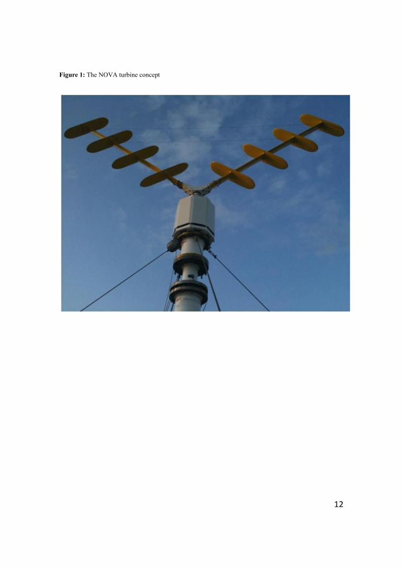
NOVA 3 turbine is a vertical axis wind turbine where the philosophy of the design is to create a low value
of the overturning moment with the aid of the sails attached to the V-shaped rotor. Figure 1 shows the
concept of the NOVA aerogenerator 4. In this design, the wind forces on the sails will result in an
overturning moment which counteracts the overturning moment generated by the action of the wind on the
V-shaped arms, and therefore the effect of the sails is a net reduction in the algebraic value of the
overturning moments.
The effect of the sails in reducing the overturning moment can be described as follows. The effect of wind
force on the arm is translated as a net overturning moment and a shear force at the base of the arm.
However, addition of a sail will create a new net force acting on the sail, which when translated to the hub,
will act as a net shear force, and since the line of action of the resultant force acting on the sail is not
parallel to the arm, this results in a net overturning moment. The relative direction of this component of

3
overturning moment about the hub depends on the angle at the intersection between the sail and the arm, as
shown in Figure 2. As can be seen from the figure, by changing the direction of the wind, the directions of
the two overturning moments from the arm and the sail change and therefore this counteracting effect still
holds.
2. EXPERIMENTAL TESTING
Experimental testing is one of the most important tools in the development process of a new design, since it
can provide real data that will advance the design or, when executed in a later phase, can reveal potential
issues that need more consideration. This is applicable in the case of any new technology 5, or in cases
where proven technologies are employed in new environments, and stands as a basic requirement towards
certification. Beheshti 6 gives an analytical procedure of a comprehensive design process that can also be
applicable to the design of experiments. In the DnV classification note 30.6 7, a classification of
uncertainties is presented distinguishing physical, measurement, statistical and model uncertainties. In the
present paper, the effect of model uncertainty will be investigated as a source of uncertainty based on
imperfections and idealisations made on the design of the physical model due to the inability to predict the
actual loading conditions.
In field testing, the effects of environmental loads are significant but difficult to predict. On the other hand,
and this is particularly important in the measurement of forces, the response of the structure should be of a
certain magnitude within specific limits in order that these can be reliably measured. In this case, where
the wind is the basic ‘input’ of the system, the effect of its uncertain magnitude can directly influence the
reliability of the testing results as well as the duration and total cost of the experiment.
The mechanism devised and the procedure that was followed for the NOVA wind turbine testing are
applicable to any wind turbine, or indeed in any similar experiment where the magnitude of the measured
forces is not known beforehand. This design and the associated procedure are presented in this paper.
4
3. PROBLEM DEFINITION
One of the key advantages of the vertical axis wind turbine configurations is the low overturning moment
when compared to conventional horizontal axis wind turbine designs. The magnitude of the static
overturning moment with the rotor parked (stationary rotor) in extreme gust cases is however, a critical
design parameter for the overall design concept. Static overturning moment data is hence a valuable
measurement for the design and optimization studies and subsequent certification.
In the experiment outlined herein, in order to measure the lateral force and overturning moment exerted by
the stationary rotor, the rotor was mounted on a platform on top of a slender tubular structure. The
additional height provided by the tower enabled the rotor to experience clean, undisturbed wind, with no
buildings or other obstructions to generate turbulence. In addition to this, as described in the next section,
the tubular tower allowed attachment of two sets of strain gauges at different elevations on the tower in
order to obtain the data required to calculate the overturning moment and the horizontal force. The tower
along with the rotor is shown in Figure 3. Measurements are taken for stationary rotor with different
orientations. The final results are sorted in terms of the relative angle between the wind and the rotor.
3.1. CALCULATION PROCEDURE
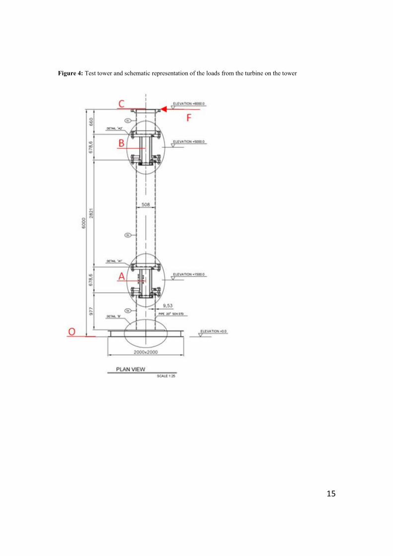
By experimentally obtaining the bending moments at two different heights on the tower, the overturning
moment and the net horizontal force can be evaluated. These bending moments will be obtained from the
straingauges mounted on the tower. Considering known values for this bending moment at the locations A
and B as shown schematically in Figure 4, the rotor overturning moment and net horizontal force will be
calculated as follows, the effect of wind drag on the tower can also be accounted for as a linear distribution
of lateral force along the length of the tower:
@ = + ×
@ = + ×
5
→ = @ − @
→ = @ ×
− @ ×
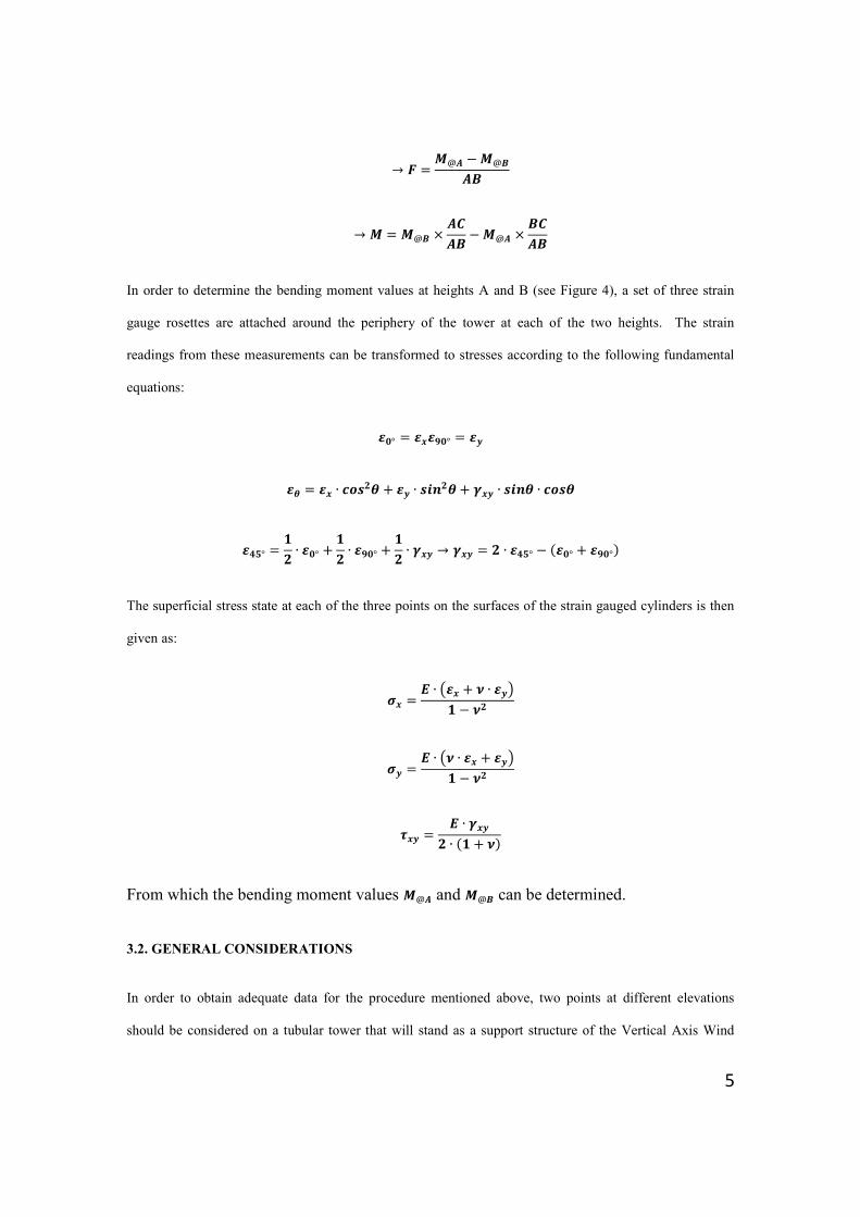
In order to determine the bending moment values at heights A and B (see Figure 4), a set of three strain
gauge rosettes are attached around the periphery of the tower at each of the two heights. The strain
readings from these measurements can be transformed to stresses according to the following fundamental
equations:
° = ૢ ° =
= ∙ + ∙
+ ࢽ ∙ ∙
° =
∙ ° +
∙ ૢ ° +
∙ ࢽ → ࢽ = ∙ ° − °) + ૢ °)
The superficial stress state at each of the three points on the surfaces of the strain gauged cylinders is then
given as:
= ∙ ൫ + ∙ ൯
−
= ∙ ൫ ∙ + ൯
−
= ∙ ࢽ
∙ (+ (
From which the bending moment values @ and @ can be determined.
3.2. GENERAL CONSIDERATIONS
In order to obtain adequate data for the procedure mentioned above, two points at different elevations
should be considered on a tubular tower that will stand as a support structure of the Vertical Axis Wind
6
Turbine (Figure 4). The tower should be designed to resist the dead load of the turbine as well as its
operational loads. This refers to a torsion load due to the rotation of the rotor, an overturning moment and
a thrust force due to the drag of the tower and the rotor against the wind. The response of this prototype
structure to wind is considered initially to be unknown. However, strain gauges are most accurate within a
certain, relatively narrow range of applied stresses, and overdesign of the structure would result in very low
and therefore unreliable and inaccurate measurements. Therefore the optimum ‘window’ of stiffness has to
be evaluated in order to obtain reliable stress values in a safe manner.
3.3. DETAILS OF THE MEASUREMENT MECHANISM
The issue of the unknown response of the structure, considering also the unknown wind conditions at the
design phase, is dealt with by employing two concentric tubes that can be operated individually, giving
strain measurements within the acceptable accuracy range of the strain gauges; the mechanism is shown in
Figure 5. The dimensions of the tubes selected are based on a design assuming normal wind conditions for
the proposed testing site (RAF Bentwater, Suffolk, UK) that where based on existing data records 8 for a
normal wind velocity of 12 m/sec and for the response of the structure, a conservative drag calculation was
employed. Since the response of the structure is unknown, the smaller diameter tube will be operated in
case of a wind or response of the structure lower than expected so that the strains are high enough in
magnitude to be accurately detected by the strain gauges.
The details in the two elevations have been sized individually to account for the different loads they have to
resist. Obviously the lower detail consists of tubes with greater thicknesses as they have to resist the dead
load of the intermediate part of the tower and, more importantly, the magnified overturning moment due to
distance of the applied forces.
In normal conditions, initial measurements are taken with the large cylinder engaged. At this layout, the
inner-smaller diameter cylinder will remain loose inside the large one, carrying no load. If those
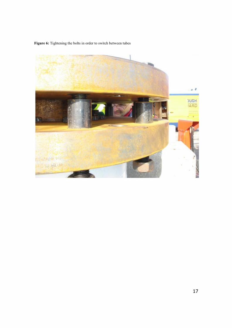
measurements are found to be small, the smaller tube will be put into operation by tightening the inner set
of bolts through the clearance between the bottom slip-on and blind flange as shown in Figures 5 and 6. In
this case, bolts of higher grade, 12.9, were selected with nuts welded below on the smaller flange, in order

7
to axially carry the distributed weight of the structure and therefore be able lift and engage the smaller
cylinder and allow the larger pipe to become load-free. When the larger tube is in operation, this clearance
is kept fixed, through the use of adequate size collars.
For safety reasons, in conditions of extreme wind speed, guyed wires are connected from eyebolts on the
top flange reaching to fixed concrete ballast at ground level. For the weaker details, 500 mm collars stiffen
the smaller cross section and studs from the upper slip-on flange through the collars and the lower set of
flanges are used. Figure 6 shows where the bolts are tightened in order to switch between the load-carrying
tubes.
It was found during the experiment that switching from the outer cylinder to the inner one so that all the
loads are carried by this cylinder was easily achievable using conventional tools. However, it must be
noted here that in order to obtain accurate and meaningful measurements, one must ensure that the
disengaged tube does not carry any of the external load. This can be achieved by ensuring that the strain
readings from the gauges on this cylinder indicate ‘zero’ values as calibrated prior to the experiment.
3.4. INSTRUMENTATION
The tube gauges were applied before the flanges were welded therefore in order to resist heat, the gauges
were bonded with M Bond 600 (care was taken not to damage the cable during the welding with the use if
wetted cloths etc). Products used in the installations are BSSM 9 approved and supplied by Vishay
Measurements Group ®.
Three rosettes were installed around the periphery of the cylinders at the two elevations. In total, there
were two pairs of concentric cylinders each containing three rosette strain-gauges, giving a total of 36 strain
readings. However, at every given instance, only one of each pair of cylinders was carrying the load and
therefore a total of 18 readings were used for the final stress analysis of the tower. On each cylinder, the
three rosettes were attached around the circumference spaced at 120° as shown in Figure 7.
The installed strain-gauge system was verified and calibrated prior to measurement of overturning moment.
This was achieved by application of a known force to one of the guyed cables while all other three cables

8
were fully slack. Calibration of the rosette strain-gauge on the inner and outer cylinders was achieved by
application of an incrementally increasing force on one of the guyed wires and then decreasing the force at
similar increments and registering the strain readings. This calibration was applied to the strain-gauge
readings during the post-processing of the results.
The rosette arrangements on the tower make it possible to measure torque generated from a stationary rotor
for different wind speeds. However this can also be achieved very easily by the conventional use of
torquemeters. The torque measurements give valuable information about the power performance of the
rotating turbine. In the stationary case, however, the toque value is not an important parameter in the
design of the current experiment.
4. TEST PROCEDURE
Prior and during the experiment, the strain gauges were calibrated in order to ensure accurate strain
readings within the range expected strains. During the experiments, two tests were conducted
simultaneously: wind data mesaurement and strain measurements. The wind speed and direction was
measured throughout the testing period by use of an anemometer mounted on a scissorlift raised to the mid
height of the rotor. The strain measurements (18 channels) were collected and stored using the time
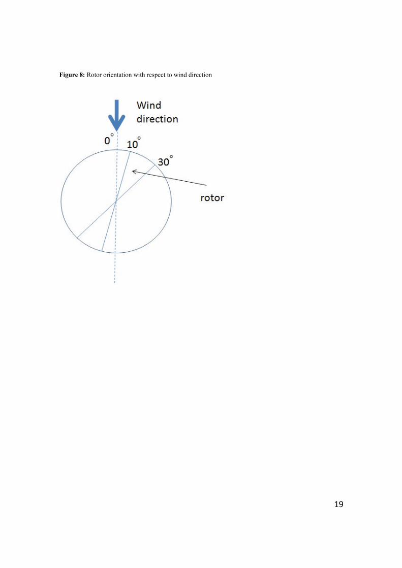
signature to allow matching of the wind and strain data. The strain measuremens were taken for different
orientations of the rotor relative to the magnetic north, the exposure time being 15 minutes for each test.
Then the combined wind-strian data were arranged for different relative angles between the wind and the
plane of the rotor. The strain results were then transformed into stresses, and subsequently into bending
moments, which then by the application of the procedure outlined in 3.1, were converted into force and
moment values for different wind velocity magnitudes.
The way the data are sorted is as follows. For each orientation of the rotor the exposure time is 15 minutes.
The data from this duration are then sorted in bins of relative wind direction. Within each band of
direction, the data are further ‘binned’ with respect to the magnitude of the wind speed. The bandwidth of
these wind speed bins are chosen in a way to contain enough data points in order to obtain a meaningful
9
mean value for each bin. The wind speed statics are also computed and the distribution of direction and
velocity magnitude have been obtained as part of the test.
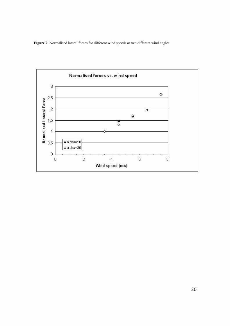
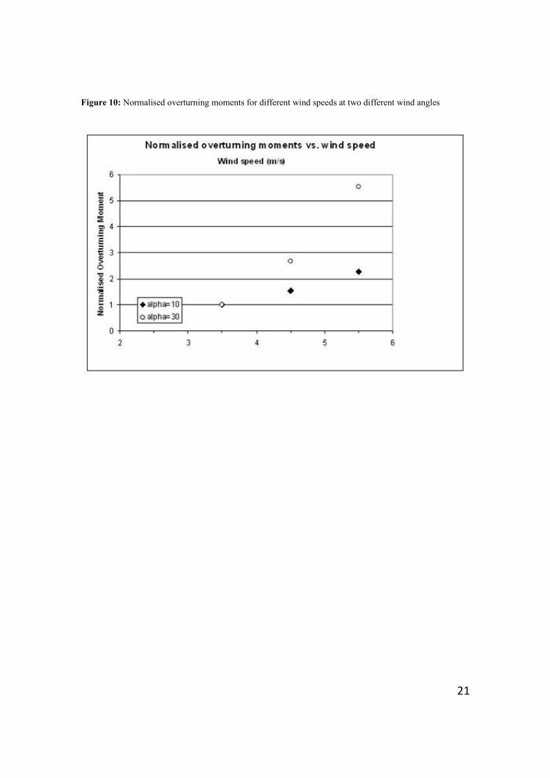
5. RESULTS
The objective of the experiments was to assess the response of the stationary rotor to different wind
conditions. From the experiments, values of the overturning moment and the lateral force were derived for
different wind speeds under different wind directions. Some of the trends obtained from these results are
shown in the Figures 9 and 10. These figures show the normalised values of the lateral force (Figure 9) and
the overturning moment (Figure 10) for two different relative wind directions, namely 10˚ and 30˚. The
trends observed in the experimental measurements of forces and moments are in general agreement with
the analytical predictions that are based on the aerofoil theory and the forces and moments acting on
stationary bodies due to the action of the wind. This simple model lacks turbulence effects and is therefore
only an indication of the trends of change of forces and moments as a function of the wind speed and
orientation.
The values of the force and overturning moment have been normalised by dividing them by the values for a
wind speed of 3.5 m/s. This would make comparison of the trends easier for different wind directions.
6. SUMMARY AND CONCLUSIONS
In this paper a novel mechanism was introduced which was used to account for the inherent uncertainty in
the loadings on the measurements sensors. In HAWTs, traditionally the effect of wind loading on the rotor
is measured by straingauge measurements at the blade root. However, this does not allow for separating
the horizontal force and the net overturning moment in the turbine. Measurement of the net horizontal
force in HAWTs is also a complicated problem but the effect of this force can be measured with relative
ease by straingaguing the tower. It is traditionally assumed that the net overturning moment at the hub
level of a HAWT is zero or negligible.
10
The double concentric tubes, along with the mechanism shown in Figue 5, allow for accurate measurement
of the reponse of the wind turbine in a range of wind speeds; some of these measured results are shown in
this paper. Experience obtained from this experiment, shows that environmental loading is a considerable
unknown that can affect the efficiency of the results. Design variations, such as use of a mechanism as
described above, can expand significantly the range of effective wind velocities between the minimum
allowed from the strain measurements and the maximum that might compromise the integrity of the test rig.
The stain-gauge double tube system also allows for some a priori uncertainty in the response of the rotor
under the action of a known wind speed, therefore showing a large scope for similar experimatation. In the
case of the NOVA test case, this range, was doubled allowing reliable measurements in an instant with low
wind velocities, avoiding undesirable delay of data collection.
Efficiency of the current method can be highlighted when compared to a method where force transducers
are used instead of strain gauge rosettes. The decoupling of the force and overturning moment is only
possible by taking measurements, by strain gauges or force transducers, at two different elevations. Use of
transducers is conditional to being able to embed them in the tower in a way to put them in the load path of
the structure. This means a more complicated design for the tower. In order to accommodate for
uncertainty in the measurement, the magnifying effect of a tower with a smaller cross section cannot be
utilized when using force transducers.
The current technique is quite versatile since fewer number of straingauges give the full force/moment data
about the turbine. A larger number of expensive transducers should be employed to derive the same data.
7. ACKNOWLEDGEMENTS
This study formed part of a project funded by the Energy Technologies Institute (ETI), a unique partnership
between global industries and the UK Government. The six current private sector partners are BP,
Caterpillar, EDF Energy, E.ON, Rolls-Royce and Shell. The ETI’s public funds are received from the
Department for Innovation, Universities and Skills (DIUS) through the Technology Strategy Board (TSB)
and the Engineering and Physical Sciences Research Council (EPSRC) with additional funding from the

11
Department for Transport.
References
1. Riegler, Hannes. HAWT versus VAWT: Small VAWTs find a clear niche . Refocus. 2003, Vol. 4, 4.
2. Sandra Eriksson, Hans Bernhoffa and Mats Leijona. Evaluation of different turbine concepts for
wind power, Renewable and Sustainable Energy Reviews. 2008, Vol. 12, 5.
3. The NOVA Project, www.nova-project.co.uk
4. Sharpe, D.J., WO/2006/054091, Vertical Axis Wind Turbine Apparatus, 2006.
5. Veritas, Det Norske. DNV-RP-A203: Qualification proceedures for a new technology. Norway : Det
Norske Veritas, 2001.
6. Beheshti, Reza. Design decisions and uncertainty. Delft University of Technology, The Netherlands :
Butterworth-Heinemann Ltd, 1993.
7. Veritas, Det Norske. 30.6 Classification Note: Structural Reliability Analysis of Marine Structures.
Norway : Det Norske Veritas, 1992.
8. http://www.tutiempo.net/en/Climate/BENTWATERS_RAF/35961.htm [Accessed online in October
2009]
9. British Society for Strain Measurement, http://www.bssm.org/
12
Figure 1: The NOVA turbine concept

13
Figure 2: Wind forces acting on the rotor

14
Figure 3: The test tower set up
15
Figure 4: Test tower and schematic representation of the loads from the turbine on the tower

16
Figure 5: Configuration of the mesurement mechanism
17
Figure 6: Tightening the bolts in order to switch between tubes

18
Figure 7: Cross section of each cylinder showing the orientation of the rosette around the tube
19
Figure 8: Rotor orientation with respect to wind direction
20
Figure 9: Normalised lateral forces for different wind speeds at two different wind angles
21
Figure 10: Normalised overturning moments for different wind speeds at two different wind angles


![Mass Moment Determination Using Compound Pendulum · Mass Moment Determination Using Compound Pendulum =G]LVáDZ3OXWD 7DGHXV]+U\QLHZLF]* Koszalin University of Technology, Raclawicka](https://img.pdfslide.us/doc/110x75/5e675384fc594749a80fbb8f/mass-moment-determination-using-compound-pendulum-mass-moment-determination-using.jpg)