Embed Size (px)
Citation preview
EXPERIMENTAL DETERMINATION OF CONVECTIVE HEAT TRANSFER COEFFICIENT IN WIRE ELECTRO DISCHARGE MACHINING
NADIAH WAZNAH BINTI ZABIDI
A report submitted in partial fulfilment of the requirementsfor the award of the degree of
Bachelor of Mechanical Engineering
Faculty of Mechanical EngineeringUNIVERSITI MALAYSIA PAHANG
NOVEMBER 2008
ii
SUPERVISOR’S DECLARATION
We hereby declare that we have checked this project and in our opinion this project is
satisfactory in terms of scope and quality for the award of the degree of Bachelor of
Mechanical Engineering
Signature : …………………………..
Name of Supervisor :
Position :
Date :
Signature : ………………………….
Name of Panel :
Position :
Date :
iii
STUDENT’S DECLARATION
I hereby declare that the work in this thesis is my own except for quotations and
summaries which have been duly acknowledged. The thesis has not been accepted
for any degree and is not concurrently submitted for award of other degree.
Signature : ………………….
Name : NADIAH WAZNAH BINTI ZABIDI
ID Number : MA 05045
Date :
ACKNOWLEDGEMENTS
First I would like to express my grateful to Allah s.w.t. as for the blessing given
that I can finish my project.
In preparing this thesis, I was contact with many people and academicians in
helping me completing this project. They have contributed toward my understanding, and
also guidance. First, I wish to express my sincere appreciation to my main thesis
supervisor Mdm Mas Ayu Binti Hassan, for encouragement, valuable guidance,
constructive criticism, advices, suggestion and motivation throughout this thesis. Without
her continued support and interest, this thesis would not have been the same as presented
here
My sincere also extends to all my beloved family especially my father Zabidi Bin
Abd Rashid and my mother Siti Hasnah Bt Sheikh Mokhsin because of if not their prayer
and support I would not be here and done this thesis. More over I would like to thanks for
all my colleagues and others who provides assistance at various occasions. Their view
and tips are useful indeed in helping me to achieve doing this thesis.
iv
ABSTRACT
Wire electro discharge machining (WEDM) is a fully extended and competitive
machining process widely used to produce dies and moulds. However, the risk of wire
breakage affects adversely the full potential of WEDM since the overall process
efficiency is considerably reduced. These symptoms are especially related to the
occurrence of an increase in discharge energy, peak current, as well as increases or
decreases in ignition delay time. Because of that, an experimental determination method
of the convective heat transfer coefficient in wire electro discharge machining is
introduced to prevent the wire breaks during running the machine. Parameters such as
peak current and flushing pressure are studied. A special device is developed to measure
the average temperature increment of the wire after a period of short circuit discharges,
and the thermal load imposed on the wire is also tracked and recorded in advance. Then,
based on the thermal model of the wire, the convective coefficient can be calculated
accurately. Some tuning experiments are carried out inside and outside a previously cut
profile to examine the influence of the kerf on the convective coefficient. With this
method, the effect of the coolant flushing pressure on the convective coefficient can be
estimated. Based on the results of the analyses, this paper contributes to improve the
process performance through a wire breakage.
v
vi
ABSTRAK
Mesin wayar nyahcas elektrik (WEDM) adalah mesin yang sangat kompetitif dan
digunakan secara meluas dalam menghasilkan acuan. Walau bagaimanapun, risiko
pemutusan wayar memberi kesan kepada potensi WEDM apabila keseluruhan kecekapan
proses semakin berkurangan. Simptom ini berkaitan dengan kejadian peningkatan
nyahcas tenaga, arus yang tinggi dan juga peningkatan serta pengurangan penangguhan
masa nyalaan percikan elektrik. Oleh sebab itu, eksperimen kaedah penentuan pemalar
peralihan haba secara perolakan dalam WEDM diperkenalkan bagi mengelakkan
pemutusan wayar berlaku semasa mengendalikan mesin. Faktor pengehad seperti arus
dan tekanan simbahan penyejuk juga dikaji. Purata kenaikan suhu wayar selepas nyahcas
litar pintas dan beban haba yang dikenakan pada wayar dicatat. Kemudian berdasarkan
model haba, pemalar perolakan haba dapat di tentukan dengan tepat. Beberapa
eksperimen dijalankan untuk mengkaji kesan laluan pemotongan bahan ke atas pemalar
peralihan haba secara perolakan. Tekanan simbahan penyejuk juga digunakan semasa
eksperimen dan kesan tekanan simbahan ini ke atas pemalar peralihan haba secara
perolakan juga dikaji.
vii
TABLE OF CONTENTS
Page
SUPERVISOR’S DECLARATION ii
STUDENT’S DECLARATION iii
ACKNOWLEDGEMENTS iv
ABSTRACT v
ABSTRAK vi
TABLE OF CONTENTS vii
LIST OF TABLES xi
LIST OF FIGURES xii
LIST OF SYMBOLS xiii
LIST OF ABBREVIATIONS xx
CHAPTER 1 INTRODUCTION
1.1 Research Background 1
1.3 Problem Statement 2
1.3 Project Objectives 2
1.4 Project Scopes 2
CHAPTER 2 LITERATURE REVIEW
2.1 Introduction of WEDM 3
2.2
2.3
WEDM Function
WEDM Operating System
4
4
2.3.1 Operation Panel 5 2.3.2 Dielectric Fluid 6
2.4
2.5
Milling Machine
Material
2.5.1 Wire Materials
7
9
9
viii
2.5.2 Mechanical Properties of Brass Wire 10
2.5.3 Workpiece Material 11
2.5.4 Temperature Distribution for Brass Wire Material 12
2.6 Convective Heat Transfer 12
2.6.1 Forced Convection 13
2.6.2 Free Convection 14
2.6.3 Convective Heat Transfer Coeficient 14
2.7 Kerf 16
2.8 Coolant Flushing Pressure 17
CHAPTER 3 METHODOLOGY
3.1 Introduction 18
3.1.1 Experiment Flowchart 20
3.2 Identify Process 21
3.3 Experiment 24
3.3.1 Experimental Determination of the Joule Heat Flux 24
3.3.2 Experimental System for Determining the Average 26
Temperature Increment of the Wire
3.4 Data Collection 27
CHAPTER 4 RESULT AND DISCUSSION
4.1 Output Voltage 29
4.2 Temperature Increment 33
4.3 Temperature with Different Flushing Pressure 35
4.4 Effect of the Kerf on the Convective Coefficient 36
ix
CHAPTER 5 CONCLUSION AND RECOMMENDATION
5.1 Conclusion 38
5.2 Recommendation 39
REFERENCES 40
APPENDIX 41
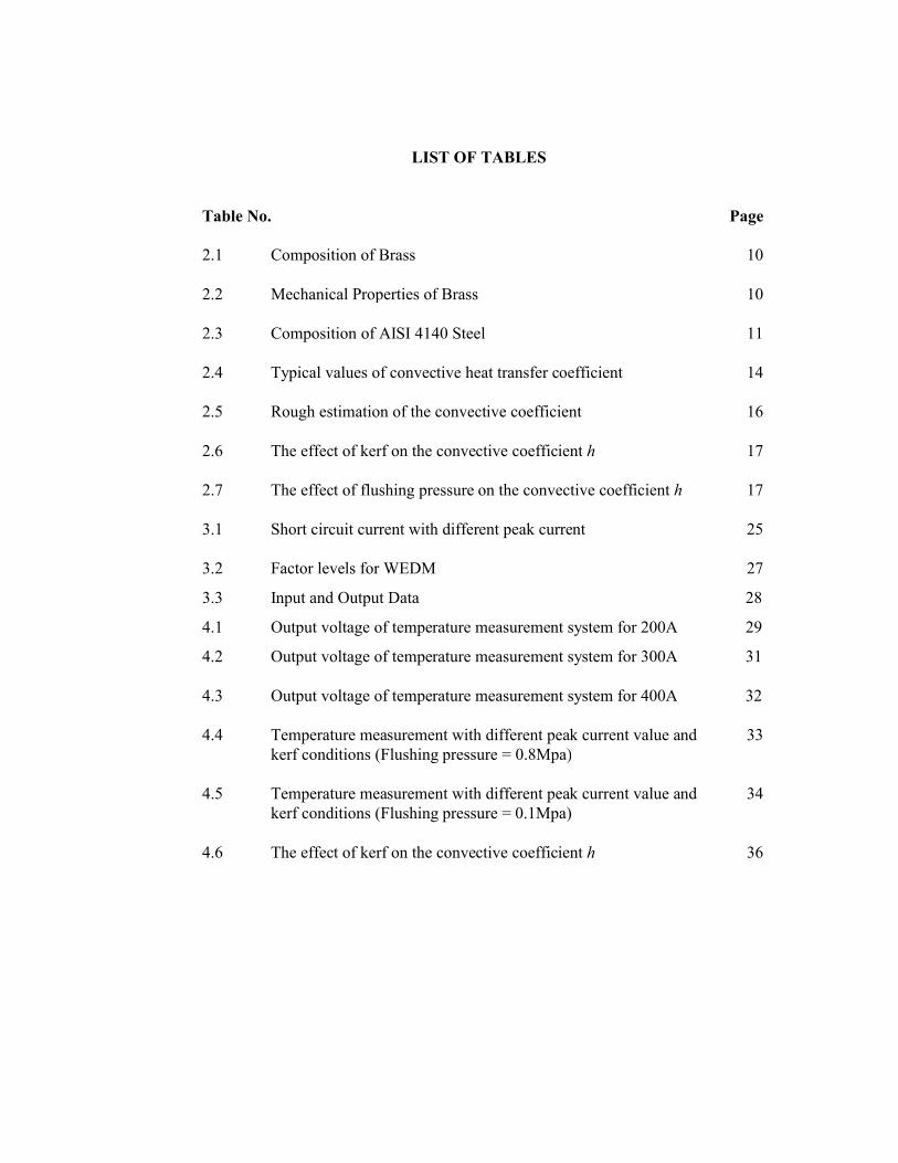
LIST OF TABLES
Table No. Page
2.1 Composition of Brass 10
2.2 Mechanical Properties of Brass 10
2.3 Composition of AISI 4140 Steel 11
2.4 Typical values of convective heat transfer coefficient 14
2.5 Rough estimation of the convective coefficient 16
2.6 The effect of kerf on the convective coefficient h 17
2.7 The effect of flushing pressure on the convective coefficient h 17
3.1 Short circuit current with different peak current 25
3.2 Factor levels for WEDM 27
3.3
4.1
Input and Output Data
Output voltage of temperature measurement system for 200A
28
29
4.2 Output voltage of temperature measurement system for 300A 31
4.3 Output voltage of temperature measurement system for 400A 32
4.4 Temperature measurement with different peak current value and kerf conditions (Flushing pressure = 0.8Mpa)
33
4.5 Temperature measurement with different peak current value and kerf conditions (Flushing pressure = 0.1Mpa)
34
4.6 The effect of kerf on the convective coefficient h 36
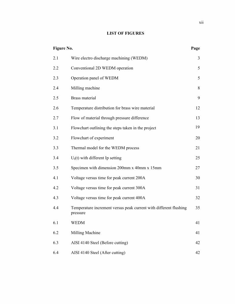
LIST OF FIGURES
Figure No. Page
2.1 Wire electro discharge machining (WEDM) 3
2.2 Conventional 2D WEDM operation 5
2.3
2.4
Operation panel of WEDM
Milling machine
5
8
2.5 Brass material 9
2.6 Temperature distribution for brass wire material 12
2.7 Flow of material through pressure difference 13
3.1
3.2
Flowchart outlining the steps taken in the project
Flowchart of experiment 20
3.3 Thermal model for the WEDM process 21
3.4
3.5
UI(t) with different Ip setting
Specimen with dimension 200mm x 40mm x 15mm
25
27
4.1 Voltage versus time for peak current 200A 30
4.2 Voltage versus time for peak current 300A 31
4.3 Voltage versus time for peak current 400A 32
4.4
6.1
6.2
6.3
6.4
Temperature increment versus peak current with different flushing pressure
WEDM
Milling Machine
AISI 4140 Steel (Before cutting)
AISI 4140 Steel (After cutting)
35
41
41
42
42
19
xii
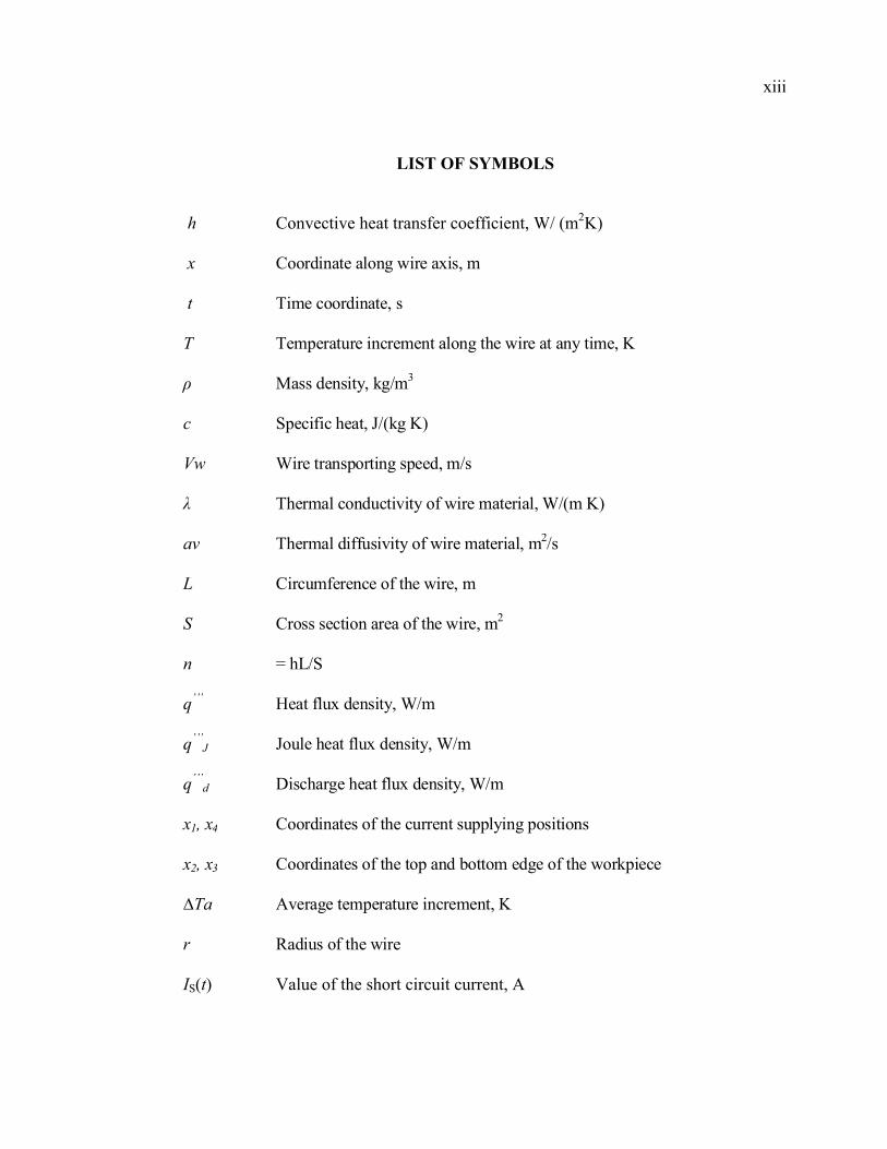
LIST OF SYMBOLS
h Convective heat transfer coefficient, W/ (m2K)
x Coordinate along wire axis, m
t Time coordinate, s
T Temperature increment along the wire at any time, K
ρ Mass density, kg/m3
c Specific heat, J/(kg K)
Vw Wire transporting speed, m/s
λ Thermal conductivity of wire material, W/(m K)
av Thermal diffusivity of wire material, m2/s
L Circumference of the wire, m
S Cross section area of the wire, m2
n = hL/S
q’’’
q’’’J
Heat flux density, W/m
Joule heat flux density, W/m
q’’’d Discharge heat flux density, W/m
x1, x4 Coordinates of the current supplying positions
x2, x3 Coordinates of the top and bottom edge of the workpiece
∆Ta Average temperature increment, K
r Radius of the wire
IS(t) Value of the short circuit current, A
xiii
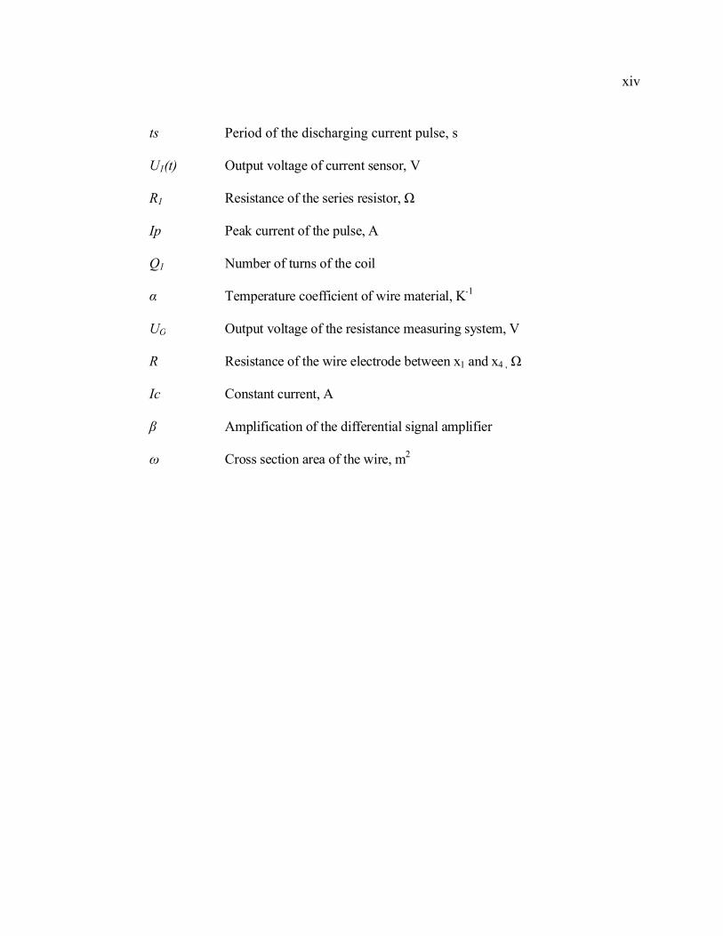
ts Period of the discharging current pulse, s
U1(t) Output voltage of current sensor, V
R1 Resistance of the series resistor, Ω
Ip Peak current of the pulse, A
Q1 Number of turns of the coil
α Temperature coefficient of wire material, K-1
UO Output voltage of the resistance measuring system, V
R Resistance of the wire electrode between x1 and x4 , Ω
Ic Constant current, A
β Amplification of the differential signal amplifier
ω Cross section area of the wire, m2
xiv
LIST OF ABBREVIATIONS
WEDM
AISI
Wire electro discharge machining
American iron steel institute
xx
CHAPTER 1
INTRODUCTION
1.1 RESEARCH BACKGROUND
Wire electrical discharge machining (WEDM) is an adaptation of the basic
EDM process, which can be used for cutting complex two and three dimensional
shapes through electrically conducting materials. WEDM utilizes a thin,
continuously moving wire as an electrode [10]. It is a relatively new process and
applications have grown rapidly, particularly in the tool making field. The wire
electrode is drawn from a supply reel and collected on a take up reel. This
continuously delivers fresh wire to the work area. The wire is guided by sapphire or
diamond guides and kept straight by high tension, which is important to avoid
tapering of the cut surface [6]. High frequency dc pulses are delivered to the wire and
workpiece, causing spark discharges in the narrow gap between the two. A stream of
dielectric fluid is directed, usually coaxially with the wire, to flood the gap between
the wire and the workpiece [7]. The power supplies for WEDM are essentially the
same as for conventional EDM, except the current carrying capacity of the wire
limits currents to less than 20A, with 10A or less being most normal. WEDM is most
commonly used for the fabrication of press stamping dies, extrusion dies, powder
composition dies, profile gages and templates [10].
2
1.2 PROBLEM STATEMENT
In WEDM process, the heat generated by continuous discharges will lead to
the temperature increment and local erosion of the wire and consequently lower its
tensile strength. Contradictorily, it is necessary to keep the wire tension at high level
in order to guarantee the machining accuracy. To prevent the wire from breaking, the
machining processes must take place in ionized water bath which not only aids in the
sparking mechanism, but also helps cooling the wire. The accurately determined
convective heat transfer coefficient will lead to exact analysis and hence will be
helpful for the prediction of the wire breakage.
1.3 PROJECT OBJECTIVES
The objectives of this project :
i) To determine the convective heat transfer coefficient in WEDM.
ii) To discover the effect of the kerf on the convective coefficient.
iii) To investigate the effect of the flushing pressure on the convective
coefficient.
1.4 PROJECT SCOPES
This project concentrates on determining the convective heat transfer
coefficient in WEDM using brass wire material with diameter 0.2mm. The
workpiece use in this project is AISI 4140 with diemension ( 200mm x 40mm x
15mm). The values of the convective coefficient change with the kerf conditions and
in the presence of coolant flushing pressure.
CHAPTER 2
LITERATURE REVIEW
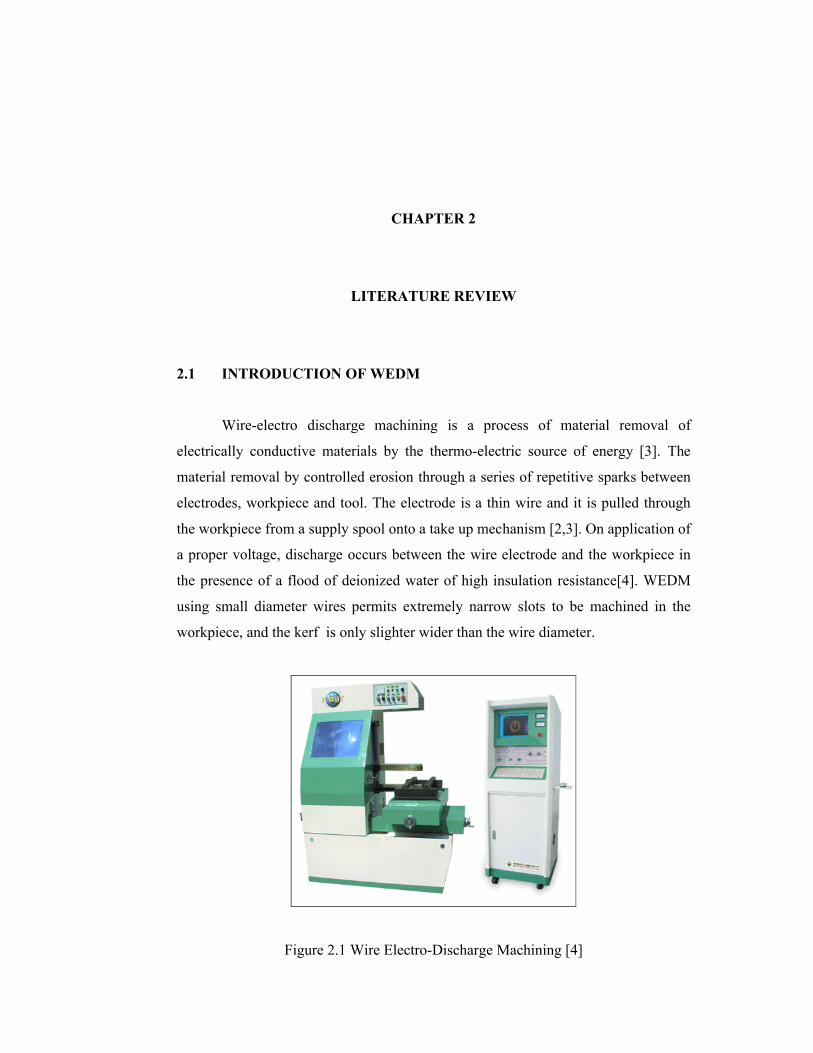
2.1 INTRODUCTION OF WEDM
Wire-electro discharge machining is a process of material removal of
electrically conductive materials by the thermo-electric source of energy [3]. The
material removal by controlled erosion through a series of repetitive sparks between
electrodes, workpiece and tool. The electrode is a thin wire and it is pulled through
the workpiece from a supply spool onto a take up mechanism [2,3]. On application of
a proper voltage, discharge occurs between the wire electrode and the workpiece in
the presence of a flood of deionized water of high insulation resistance[4]. WEDM
using small diameter wires permits extremely narrow slots to be machined in the
workpiece, and the kerf is only slighter wider than the wire diameter.
Figure 2.1 Wire Electro-Discharge Machining [4]
4
2.2 WEDM FUNCTION
WEDM has advanced quickly with the addition of computer numerical
control (CNC). Today WEDM is used for a wide variety of precision metalworking
applications which would have been almost impossible just a few years ago [8].
Cutting tolerances, cutting speeds and surface finish quality have been greatly
improved [11]. Wire-cut EDM can do things older technologies cannot do as well, as
quickly, as inexpensively, and as accurately. Most parts can now be programmed and
produced as a solid, rather than in sections and then assembled as a unit that
necessary. The WEDM is capable of producing complex shapes such as tapers,
involutes, parabolas and ellipses that would otherwise be difficult to produce with
conventional cutting tools [14,15].
2.3 WEDM OPERATING SYSTEM
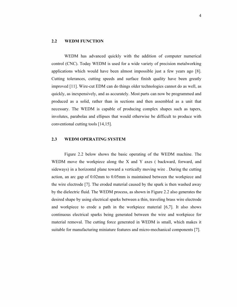
Figure 2.2 below shows the basic operating of the WEDM machine. The
WEDM move the workpiece along the X and Y axes ( backward, forward, and
sideways) in a horizontal plane toward a vertically moving wire . During the cutting
action, an arc gap of 0.02mm to 0.05mm is maintained between the workpiece and
the wire electrode [7]. The eroded material caused by the spark is then washed away
by the dielectric fluid. The WEDM process, as shown in Figure 2.2 also generates the
desired shape by using electrical sparks between a thin, traveling brass wire electrode
and workpiece to erode a path in the workpiece material [6,7]. It also shows
continuous electrical sparks being generated between the wire and workpiece for
material removal. The cutting force generated in WEDM is small, which makes it
suitable for manufacturing miniature features and micro-mechanical components [7].
5
Figure 2.2 Conventional 2D WEDM operation [2]
2.3.1 Operation Panel
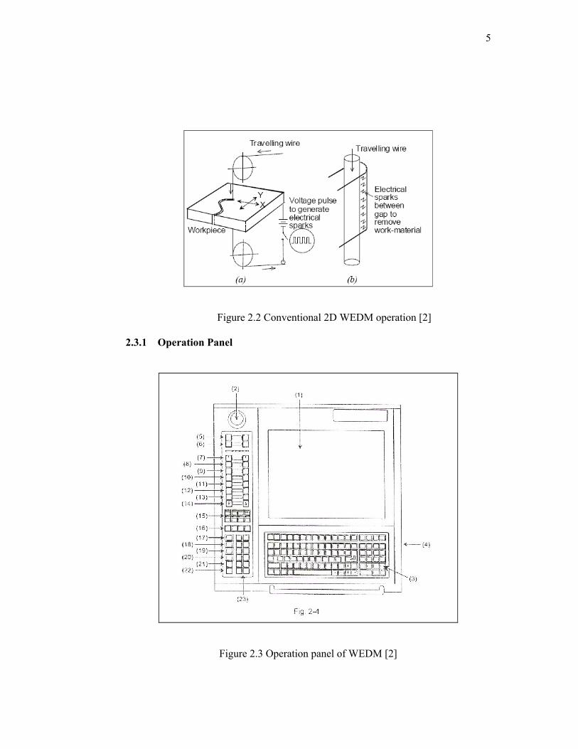
Figure 2.3 Operation panel of WEDM [2]
6
(1) LCD screen (13) [TANKDRAIN ON/OFF]
(2) Emergency stop switch (14) [TANK DOOR]
(3) Keyboard (15) Switches [A0] to [A7]
(4) Floppy disc drive (16) [MFR0] to [MFR3]
(5) [SOURCE ON/OFF] switches (17) [OFF] switch
(6) [POWER ON/OFF] switches (18) [ACK] switch
(7) [AWT CUT/TREAD] switch (19) [HALT] switch
(8) [TENSION ON/OFF] switches (20) [ENT] switch
(9) [WIRE STOP/RUN] switches (21) [ST] switch
(10) [HIGH PRESSURE ON/OFF] switches (22) [UV] switch
(11) [LOW PRESSURE ON/OFF] switches (23) Jog switches
(12) [TANK FILL ON/OFF]
2.3.2 Dielectric Fluid
One of the most important factors in a successful WEDM operation is the
removal of the particles (chips) from the working gap. Flushing these particles out of
the gap with the dielectric fluid will produce good cutting conditions, while poor
flushing will cause erratic cutting and poor machining conditions [10].
The dielectric fluid in the WEDM process is usually deionized water. This is
tap water that is circulated through an ion-exchange resin. The deionized water
makes a good insulator, while untreated water is a conductor and is not suitable for
the electrical discharge machining process[11,13]. The amount of deionization of the
water determines its resistance. For most operations, the lower the resistance the
faster will be the cutting speed [10].
7
The dielectric fluid used in the WEDM process serves several functions :
1. It helps to initiate the spark between the wire and the workpiece [2].
2. It serves as an insulator between the wire and the workpiece [2].
3. It flushes away the particles of disintegrated wire and workpiece
to prevent shorting [3].
4. It acts as a coolant for both the wire and the workpiece [3].
2.4 MILLING MACHINE
A milling machine is a machine tool used for the shaping of metal and other
solid materials. Its basic form is that of a rotating cutter which rotates about the
spindle axis (similar to a drill), and a table to which the workpiece is affixed. In
contrast to drilling, where the drill is moved exclusively along its axis, the milling
operation involves movement of the rotating cutter sideways as well as in and out
[14].
The cutter and workpiece move relative to each other, generating a tool path
along which material is removed. The movement is precisely controlled, usually with
slides and lead screws or analogous technology [13]. Often the movement is
achieved by moving the table while the cutter rotates in one place, but regardless of
how the parts of the machine slide, the result that matters is the relative motion
between cutter and workpiece. Milling machines may be manually operated,
mechanically automated, or digitally automated via CNC [14].
Milling machines can perform a vast number of operations, some of them
with quite complex tool paths, such as slot cutting, planing, drilling, diesinking,
rebating and routing. Cutting fluid is often pumped to the cutting site to cool and
lubricate the cut, and to sluice away the resulting swarf.[14].
8
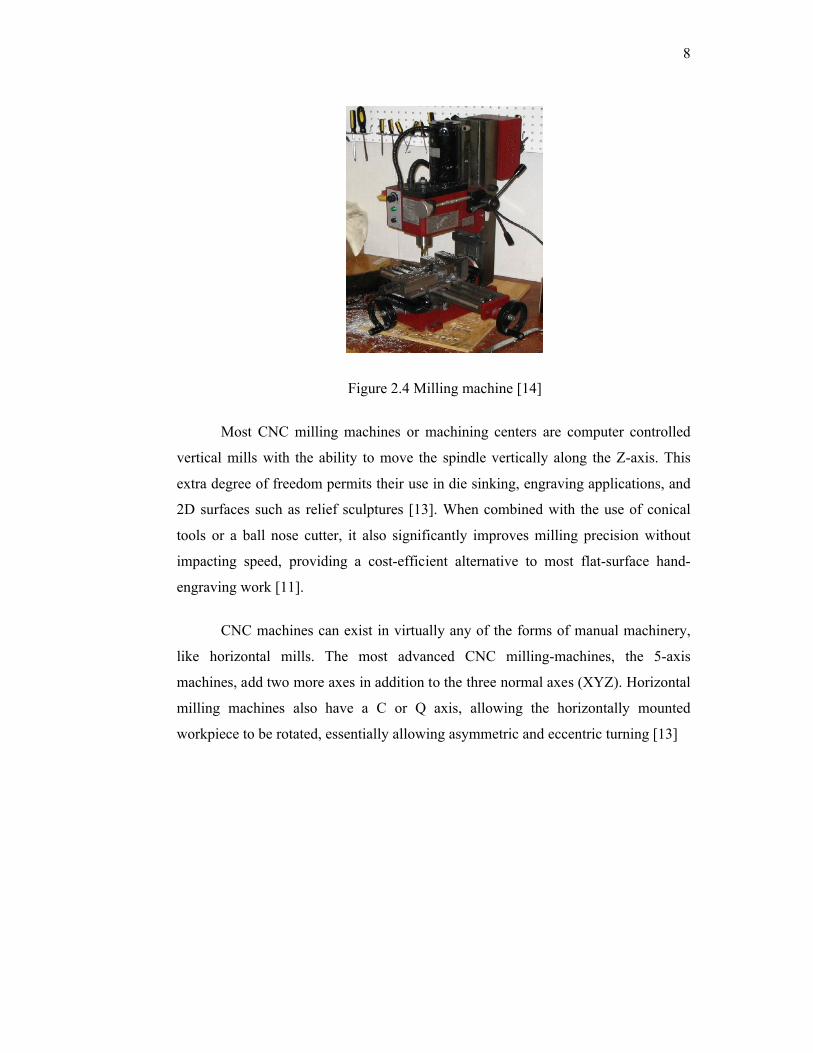
Figure 2.4 Milling machine [14]
Most CNC milling machines or machining centers are computer controlled
vertical mills with the ability to move the spindle vertically along the Z-axis. This
extra degree of freedom permits their use in die sinking, engraving applications, and
2D surfaces such as relief sculptures [13]. When combined with the use of conical
tools or a ball nose cutter, it also significantly improves milling precision without
impacting speed, providing a cost-efficient alternative to most flat-surface hand-
engraving work [11].
CNC machines can exist in virtually any of the forms of manual machinery,
like horizontal mills. The most advanced CNC milling-machines, the 5-axis
machines, add two more axes in addition to the three normal axes (XYZ). Horizontal
milling machines also have a C or Q axis, allowing the horizontally mounted
workpiece to be rotated, essentially allowing asymmetric and eccentric turning [13]
9
2.5 MATERIALS
2.5.1 Wire Materials
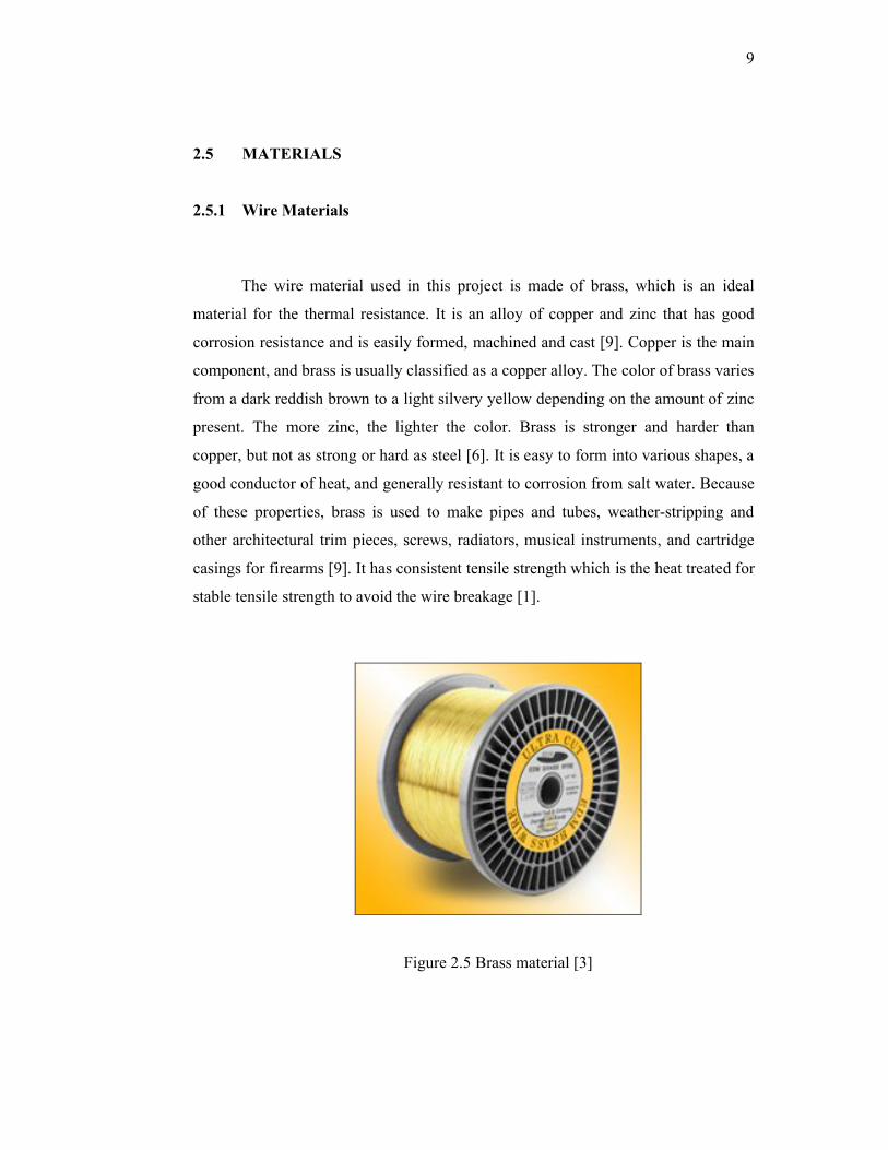
The wire material used in this project is made of brass, which is an ideal
material for the thermal resistance. It is an alloy of copper and zinc that has good
corrosion resistance and is easily formed, machined and cast [9]. Copper is the main
component, and brass is usually classified as a copper alloy. The color of brass varies
from a dark reddish brown to a light silvery yellow depending on the amount of zinc
present. The more zinc, the lighter the color. Brass is stronger and harder than
copper, but not as strong or hard as steel [6]. It is easy to form into various shapes, a
good conductor of heat, and generally resistant to corrosion from salt water. Because
of these properties, brass is used to make pipes and tubes, weather-stripping and
other architectural trim pieces, screws, radiators, musical instruments, and cartridge
casings for firearms [9]. It has consistent tensile strength which is the heat treated for
stable tensile strength to avoid the wire breakage [1].
Figure 2.5 Brass material [3]
10
2.5.2 Mechanical Properties of Brass Wire
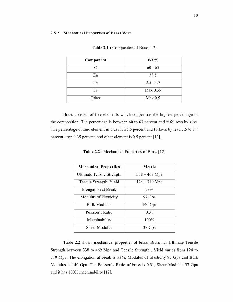
Table 2.1 : Compositon of Brass [12]
Brass consists of five elements which copper has the highest percentage of
the composition. The percentage is between 60 to 63 percent and it follows by zinc.
The percentage of zinc element in brass is 35.5 percent and follows by lead 2.5 to 3.7
percent, iron 0.35 percent and other element is 0.5 percent [12].
Table 2.2 : Mechanical Properties of Brass [12]
Mechanical Properties Metric
Ultimate Tensile Strength 338 – 469 Mpa
Tensile Strength, Yield 124 – 310 Mpa
Elongation at Break 53%
Modulus of Elasticity 97 Gpa
Bulk Modulus 140 Gpa
Poisson’s Ratio 0.31
Machinability 100%
Shear Modulus 37 Gpa
Table 2.2 shows mechanical properties of brass. Brass has Ultimate Tensile
Strength between 338 to 469 Mpa and Tensile Strength , Yield varies from 124 to
310 Mpa. The elongation at break is 53%, Modulus of Elasticity 97 Gpa and Bulk
Modulus is 140 Gpa. The Poisson’s Ratio of brass is 0.31, Shear Modulus 37 Gpa
and it has 100% machinability [12].
Component Wt.%
C 60 - 63
Zn 35.5
Pb 2.5 - 3.7
Fe Max 0.35
Other Max 0.5