Embed Size (px)
Citation preview

1
EXPERIMENTAL CONTROL e 0AF-7 @3&3--/ OF A CUPOLA FURNACE
Kevin L. Moore Mcasurcinent and Control Eng. Research d n t e r Collegc of Engineering Idaho Su te University Pocatello, ID 83209-8060 [email protected]
Eric Larsen and Denis Clark Lockliecd Martin Idaho Technologies Company Idaho National Eng. and Env. Laboratory P.O. Box 1625, Idaho Falls, ID 834 I5
Abstract
In this paper we present some final results from a resr;lrch project focused on introducing automatic control to the operation of cupola iron furnaas. The main aim of lhis research is to irnprovc tlie operational ef€icienq and performance of the cupola furnace, an important foundry process used to melt iron P m o u s papers have described the development, of appropriate conml system axhileaures for the cupola In this paper experimental data is used to calibrate the model, which is taken as a firstadex multivariable system with time delay. l i e n relative gain analysis is used to select loop pairings to be used in a multiloop conmller. The resulting controller pairs meltrate with blast volume, iron temperature with oxygen addition, and &n composition with metal-rocoke ratio. Special (nonlinear) filters are used to compute meltrate from actual scale readings of I ~ I C arnounl of iron produced and to smooth the temperam rneasureinent The temperature and meltrate loops use single- loop PI control. The composition loop uses a Smith predictor to discount die deadtime associated with m a s transport through the furnace. Experiments conducted at the Department of Energy Albany Research Center's experimental research cupola validarc die conceptual controller design and provide proof-of- concept of the idea of controlling a foundry cupola.
1 Introduction
The cupola furnace is one of the primary foundry processes uscd to meh iron. A cupola is usuaIly oonslructed as a water- coolcd vcrtical cylinder. The cupola is charged at the top wih fuel (usually coke) and metal (pig iron, scrap metal, cast iron scrap, foundry return scrap, and fwrpalloys). Air is injected into tlie cupola tluough tuyeres located near the bottom of the furnace, abovc the molten iron. The blast air is often heated and C M C I K X I with oxygen. As the coke is consumed the charge drops and mells, producing a continuous flow of molten iron (large
Mohamed A. Abdelrahman EIecuical and Computer Engineering Department Tennessee Technological University CookeviIIe, TN 38505400 1 [email protected]
Paul King U. S. Department of Energy Albany Research Center 1450 Queen Ave SW, Albany, OR 97321
cupolas may produce up 100 tordhour of hot iron). Key operational goals in cupola operation are to keep the iron properties within a prescribed range and, in some cases, to maintain a desired production rate. These goals are usually accomplished through judicious choice of the marupdated pnxzss variables, notably the blast propemes (rate, temperature, and oxygen enrichment) and the charge composition (mcludmg coke-to-metal ratio, iron-to-sleel ratio. and alloys).
Although the cupola rcmaills the primary method for melting iroq especially for high-volume production, beguuung in the 1950's various preaures led to a general decline in the domestic foundry industry. Recently lhe foundry i n d q has begun to regain its position in the world market One lhrust has been on improved understanding of the cupola pnx;esr via a modeling &on [l]. Another thrust has been on improved operation of the cupola through automauc control technology. Cupola operation has not been greatly improsed over the years and has always relied on rlie experience of the operator m deciding which p m x s parameters to adjust to &rain the desired molten iron properties. In a recent study, it was found that foreign foundries have better trained operator^ [2j These observations motivated a project funded by the Department of Energy (DOE) and the American Foundrymen's Soclety (AFS) aimed at demonstrating h e feasibility of using feedback control technology to help achieve better operation of the cupola furnace with less dependence on h e experience and s)ulls of a angle operator [3].
The DOE-AFS project team included the Idaho Nauonal Engineering and Environmental Laboratory (INEEL), a DOE national lab, Idaho State University (ISU), mearchers a1 the DOE Albany Research Center (ALRC), and an industrial oversight committee sponsored by AFS An expenmental research cupola (an eighteen inch diameter firmace wth a nominal meltrate of approximately two tonshour) wds designed. corxstmaed, and i m e n t e d at ALRC [4]. INEEL researchers developed a LabVieW-based computer instrument panel for data
This report was prepared as an account of work sponsored by an agency of the United States Government. Neither the United States Government nor any agency thereof, nor any of their employees, makes any warranty, express or implied, or assumes any legal liability or responsibility for the accuracy, completeness, or use- fulness of any information, apparatus, product. or process disclosed, or represents that its use would not infringe privately owned rights. Reference herein to any spc- cific commercial product, process, or service by trade name, trademark, manufac- turer, or otherwise does not necessarily constitute or imply its endorsement, m m - mendation. or favoring by the United States Government or any agency thereof. The views and opinions of authors expressed henin do not necessarily state or reflect those of the United States Government or any agency thereof.
DISCLAIMER
Portions of this document may be illegible electronic image products. images are produced from the best available original document.

- . - . .... . . . . . . . . . . . . . . .
acquisition and control interfacing [5,6]. INEEL also developed a ncural network model of the s teadyate cupola [6,7]. ISU. developed control concepts for the furnace. The controller architecture has a hierarchical structure hat includes system- lcvel coordination for optimization and setpoint selection and procm-level control for setpoint regulation [SI.
I n h i s paper we present some of the final process-level rcsulls from the DOE-AFS projeu Firsf, ewperimentaI data is used to define a firstader multivariable syaem with time delay. TIUS model suggests that a multiloop control strategy is sullicient for the ALRC cupola Next, relative gain analysis is uscd to S e l a loop pairings to be used in a multiloop controller. Conmllers are then defined based on the suggested pairings. The resulting controller pain meltxate with blad volume, iron lcmperature with oxygen addition, and c a h n composition with iiick+m-coke ratio. The temperature and meltrate loops we single-loop PI control. The cornpsition imp uses a Smith prediaor to handle the significant time delay asscciated with the ruoveinenl of tlx charge down the furnace. We also describe spccial filters (hat are used to compute meltrate fiom actual d e rcadings of the amount of iron produced and to smooth the tcrnpcrature meaSurement Finally, we present experimental rcsults Illat validate h e conceptual controller design and provide proof-of-concept of the idea of conmiling a foundry cupola
2 A Model of the Cupola
The cupola is a very complex dynarmcal system Unfortunately, to date there is not a complete fint-prinaples iiiodel of the cupola available. Accurate modeling of Ihe process q u i r e s careful mnsideration of chemical and physical principles. Indeed, the mosl comprehensive model available, the AFS model mentioned above, is only a onedimensional steady- state modcl and even so. involves well over forty coupled non- linear differential equations (in space) as well as numerous algebraic relations representing slochiomeu-ic and other relations However, in order to design a controller for the firme it is desirable to have a simple model that retains the main physical characteristics of the cupola For this reason a first-order multivariable model is used in the conuoller design
2.1 Manipulated and Controllcd Variable Sclcction
Based on preliminary analysis of the cupola process, information gathered from industrial cupola operators, and constraints placed by the actual instrumentation capabilities, manipulated and controlled variables were chosen in the following way:
I . Manipulafed variables (process inpurs):
2. Controlled variables (process outputs):
(a) Iron carbon content (%C) (b) Iron temperature (T,) (c) Melt rate (MR)
Although other choices of inputs and outputs could be made, such as various types of metal input streams, concentrations of other elements such as S. Si, or M n , or off- gas measurements, a decision was made to limit the scope of the proof-of-concept experiments to the fundamental signals of interest. Future acu'viry is planned to expand the number of signals used in the controller.
2.2 Transient Model
A number of transient response tests were conducted in order to build an approximate model of the system. B&use the hrnace is expensive to operate the typical procedure was to combine transient response tests with control t m . First the furnace would be started and brought to steady-state. Then a step change would be made to one of the inputs. After the furnace had settled it would be returned to its initial setting. While this was taking place steady-state gains and time constants would be computed and controller gains would be selected. Then, during the final part of the run, the controller would attempt lo regulate the furnace to a new setpoint. Six experimental runs of this nature were executed using only blast rate and oxygen enrichment. Two other runs were performed to study the transients associated with changes in coke-to-metal ratio. All tests were conducted starting from the same nominal operating point (blast rate of 300 scfm, no oxygen enrichment, and 12% coke-to-metal ratio). From these eight tests a transient model was developed. This model was used to design the controllers used in the final experiment described below.
As we have noted, the transient model is a first-order multivariable system with timedelay. The transfer matrix derived from the transient tests is given by: -
0.03 0
- 0.04 e - 300s + I 300s + 1
- 75 1 2 O [*;SI [A%%-]=
A */e c 4 e
~ ~
3001 + 1 300s + I 2 0.08 ~- 0.04 e - '*
3003 + I 3 O O s + I 6 0 ~ + I J
The time delay T was determined to be one hour. or 3600 seconds. Notice that this i s much longer than the five minute lime constant seen i n most entries. Also note that we have espressed the model in terms of deviations from nominal
(a) Coke-to-metal ratio (CMR) @) Oxygen enrichment (0,) (c) Blast rate (BR)

,
3 Controller Design
3.1 Controllcr Structure
I t is clear from the dynamic model that one of the iiiputs, the coke-to-metal ratio, is delayed, while the other two, the oxygen ennchment and the blast rate, are undelayed. These points were understood to be true in the carly stages of the project. Consequently, we initialiy designed controllers based on these observation and on stcady-sate assumptions about the process obtained from analysis of the AFS model. These designs are described in 19) and (IO). In these earlier works it was assumed that the carbon content would be afieaed only by the CMR while the iron temperature and the melt rate would be affected by cach of [lie three inputs The design of the control system could be greatly simplified if the effect of the delayed and undelayed inpuu are completely decoupled. Thus, the proposed control system architecture for the cupola, described in [ 101 had three key parts:
I A feed forward controller - decouples the delayed and undelayed parts of the dynamical model.
2 Coke-to-metal ratio (CMR) controller - required to work with a long uncemin time delay. This controller was proposed to be a Smith predictor with a robust controller to handle uncertainty in the time delay Oxygen (0,) and blast rate (BR) controllers - acts with nodelay. These were proposed to be multivariable PI controllers designed using an LQR procedure
3
However, after the experimental dynamic model was available a decision was made to use a simpler overall approach during the implementation. First, because the delay time associated with the charge input is so much longer than the time constants of the system, it seems that the decoupling of the delayed input from the temperature and meltrate is not really necessary. Also, it can be seen that there is quite a bit of natural decoupling inherent in the system. In particular, because the dynamics associated with tlic blast rate input are faster than those associated with oxygen and because blast rate has no effect on temperature in the ALRC cupola, i t Seems that there is no real need for a multivariable controller associated with h e undelayed inputs. Tliese observations led us to implement a multiloop control strategy. Although we retained the Smith predictor, we did not keep any feedforward elements. Also, because of tlic first-ordcr nature of all the transfer matrix entries, we used simple PI controllers.
3.2 Inl)ut-Output Pairing Analysis
To implement a multiloop controller it is necessary to decide which input should be paired with which outputs. Although we might observe that coke-to-metal ratio is an
obvious candidate for pairing wkh the percent carbon in the iron, it is useful to consider the issue more systematically. A tool commonly used in the process control community is the so-called relative gain analysis, which is based on the steady-state gain matrix, which we denote K,. The relative gain matrix, R, is computed as
T R = K ss *.( K;’)
where “*.” denotes entry-by-enlry multiplication The entries of the relative gain amy matrix prwide a measure of the effect of interadion in a rnultiloop control system It can be shown that one should use loop pairings that have relative gain array entries Lhat are positive and close to unity.
For the ALRC cupola the steadystate gain matrix is defined by
A%C
From this we can compute the relative gain array matrix:
This matrix makes it clear that. from the perspective of loop gain interactions, the following loop pairings should be used:
1. %Carbon controlled using coke-to-metal ratio. 2. Temperature controlled using oxygen. 3. Meltrate controlled using blast.
3.3 Controller Impicmentation
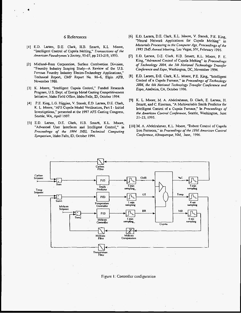
Using the input-ou[put pairings given above, we end up with the control system block diagram shown in Figure 1. The Smith predictor structure is standard and uses a PI controller (this is indicated by the leners “PID” in the block denoted “Smith predictor” in the figure). All controllers shown in the figure were implemented digitally, using LabView. Four points should be noted:
I . The control system is actually a cascade controller, where the controllers we have described here are actually used to drive the setpoints for the instrument-level controllers. The one exception to this is the coke-to-metal ratio. This loop was implemented in a semi-automatic fashion as follows. The controller took measurements from the data acquisition portion of the Labview system and computed the appropriate changes to the coke-to-metal ratio. These
changes were displayed on the monitor and were then rclaycd via two-way radio to penonnel charging the cupola.
2. Due to hardware and data acquisition constraints there were a number of different sampling times in the actual implementation. These are also indicated in Figure 1.
3. AH of the key output signals suffered from noise problems. As a result, it was necessary to use various filters in the control system. For %Carbon and temperature the filters were simple averaging filters. For temperature we averaged and also applied hardlimiters and standard deviation filters to reject measurements that were too far out of range to be true. This was necessary because we were using an unreliable pyrometer to measure the temperature of tlic molten iron. Getting a good meltrate measurement was a more challenging problem. This was because the only available measurement was the actually weight of iron. Thus it was necessary to differentiate the measurement of weight to get meltrate (weight per unit time). The technique used to do tliis was to compute a least-squares fit of a line to a fixed number of weight readings. The slope of this line, which was also passed through hardlimiters and standard deviation filters, is the meltrate. A more complete descnption of the various signal filters will be included in [lie final version of the paper.
4. Actual controller gains were chosen via simulation. Closed-loop poles were chosen so that there was no overshoot in any signals in the simulated experiments. This was done using standard root locus-based design and then checked via simulation. The resulting controller had the forin:
where E denotes the error Signal. The Smith predictor used to regulate carbon concentration has the form
a s ) - TS C,(S) =
1 + C(s)C(s)( 1 - e ) where
0.0 3 C(s) = 0.1 + -
S
0.04 G(s ) = -
300s + 1
The other two controllers are given by:
-4 2.8 x I O c2 ( 5 ) = 0.1 + S
0.03 C, (5) = 3.0 + - .I
S
4 Experimental Results
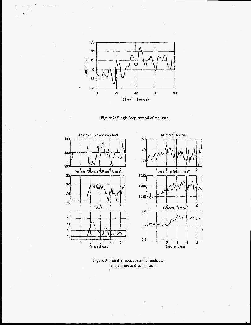
As noted, a number of experiments were conducted. We began with single-loop control of meltrate and temperature, one at a time. A representative result is shown in Figure 2, which gives the output response of an experiment to oontrol meltrate by adjusting the blast input. The setpoint in this experiment was 45 Ibdmin. Notice that the meltrate shows significant variation about the setpoint. Analysis has shown that this variation is real and reflects how hard it is to control the cupola. M e r completing a number of single-loop experiments. we demonstrated multiloop control of meltrate and temperature simultaneously. We then conducted a single-loop control experiment to regulate the carbon concentration using the Smith predictor. The final expenment consisted of demonstrating simultaneous control of all three outputs of interest: meltrate, temperature, and percent carbon. In the interest of space we will only discuss the final experiment. The sequence of events was as follows:
1, n i e furnace was stafled and brought to steady-state. 2. The controllers were turned on.
Meltrate setpoint was 40 Ibslmin. Iron temperature setpint was 1400 degrees C . %Carbon setpoint was 3.3%.
3. M e r about three hours the meltrate setpoint was changed to 35 Ibsfmin.
Figure 3 shows the results of the experiment. The plots on the left are the manipulated variables and the plots on the right are the respective controlled variables that are paired with each manipulated variable. It is clear that the controller is efiective in driving the system to the desired setpoints.
5 Conclusion
I n this paper we have presented experimental results that demonstrate the feasibility of using automatic control to regulate primary process variables in the foundry cupoIa. In future work these ideas will be incorporate into an integrated intelligent measurement and control system. It is expected that application of these ideas in an industrial setting will result in significant operational benefits.
6 References
[ I t E.D. Larsen, D.E. Clark. H.B. Smartt, K.L. Moore. “Intelligenl Control of Cupola Melting,” Transactions oJ the Amencan Foundrymen *s Society. 95-67, pp 2 15-2 19,1995.
121 Midland-Ross Corporation. Surface Combustion Division, “Foundry Industry %ping Study-A Review of the U.S. Ferrous Foundry Industry ElectreTexhnology Applications,” Technical Report. CMP Report No. 86-6, Elgin AFB. November 1986.
131 K. Moore, “Intelligent Cupola Control,’’ Funded Research Program. U.S. Dept. of Energy Metal Casting Competitiveness Initiative. Idaho Field Office, Idaho Falls, ID, October 1994.
P.E. King. L.G. KjgginS, V. Stanek, E.D. Larsen, D.E. Clark. K. L. Moore, “AFS Cupola Model Verification, Part I - Initial Investigations,” presented at ~e 1997 AFS Casting Congress, Seallle. WA. Apnl 1997.
141
[6] E.D. Larsen, D.E. Clark, K.L. Moore, V. Stan& P.E. King, ‘ W e u I Network Applications for Cupola Melting” in Materials Processing in the Computer Age. Proceedings ofthe 1995 lMS Annual Meeiing. Las Vega . NV, February 1995.
[7] E.D. Larsen, D.E. Clark, H.B. Smartt, K.L. Moore, p. E. King, “Advanced Control of Cupola Melting” in Proceedings of Technology 2004. the 5th Nation01 Technology Tmnsfer Conference and Expo, Washington, DC, November 1994.
[S] ED. Larsen, D.E. Clark, K.L. MOOR. P.E. King. Yntelligent Control of a Cupola Furnace,” in Proceedings of Technoloa 2006. the 6th Nafional Technology Tmnsfer Conference and &p, Anaheim. CA. October 1996.
[9] K. L. Moore, M. A. Abdelrahman. D. Clark. E. Larsen. H. S m a and C. Einerson, “ A Multivariable Smith Predictor for Intelligent Control of a Cupota Furnace,” In Proceedings of the American Control Conference. Seattle. Washington, June 21-23. 1995.
[ S t E.D. Larsen. D.E. Clark, H.B. Smartt, K.L. Moore. “Advanced user hterfam and Intelligent con~o]; in [Io] M. A. Abdelrahman. K.L. Moore, ‘Tobust Control of Cupola Proceedings of the 1994 INEL Technical Computing Iron Furnaces,” in Proceedings of the 1996 American Control Symposium, Idaho Falls, ID, October 1994. Confirence. Albuquerque, NM. June, 1996.
Figure 1: Controller configuration
55
50
45 - c z Ll
E 240
35
30 V
0 20 40 60 80
Time (minutes)
Figure 2: Single-loop control of meltrate.
Blast rate (Sp axl x n b a r ) 400
300
200
35
30
25
20 - 4 5 ' CMA
M&ate (Wnin)
40
30 I 1 I I ' 1 I I I . . I
7 450
1400
1350
3.5 16
14
12
10
3
2.5 1 2 3 4 5 1 2 3 4 5
Time in hars Gme in hous
Figure 3 : Simultaneous control of meltrate, temperature and composition,