Embed Size (px)
Citation preview

ARTICLE IN PRESS
Marine Structures 20 (2007) 238–254
0951-8339/$ -
doi:10.1016/j
�CorrespoE-mail ad
www.elsevier.com/locate/marstruc
Experimental and numerical study on tuned liquiddampers for controlling earthquake response of
jacket offshore platform
Qiao Jina, Xin Lia,�, Ning Suna, Jing Zhoua, Jiong Guanb
aState Key Laboratory of Coastal and Offshore Engineering, Dalian University of Technology, Dalian 116023, ChinabIKM Ocean Design, Postboks 99, 4064 Stavanger, Norway
Received 23 October 2006; received in revised form 8 May 2007; accepted 10 May 2007
Abstract
Earthquake loading has to be considered when the offshore platform is constructed in active fault
zone. Tuned liquid dampers (TLD) have been proposed to control the dynamic response of
structures. Liquid sloshing experiments on cylinder tank show the sloshing happens more seriously
when the frequency of external excitation is close to the fundamental sloshing frequency of liquid.
Lumped mass method is employed to numerically analyze the controlling earthquake effect on TLD.
Based on TLDs the feasibility to control earthquake response of jacket platform is studied and
applied to CB32A oil tank platform. Using extra TLDs in CB32A to control the seismic response of
the platform is researched by the model test and numerical simulation. Lumped mass method can
simulate the behavior of TLD during earthquake very well and gives close numerical results
compared with those from model experiments. It has been found that the ratio of the fundamental
sloshing frequency of liquid to the natural frequency of platform is the key factor to control
earthquake response. The larger ratio of water-mass to platform-mass is also useful to reduce
vibration as well.
r 2007 Elsevier Ltd. All rights reserved.
Keywords: Jacket platform; Tuned liquid dampers; Sloshing; Earthquake response; Vibration control; Model test;
Numerical simulation
see front matter r 2007 Elsevier Ltd. All rights reserved.
.marstruc.2007.05.002
nding author. Tel.: +86 411 84707805; fax: +86 411 84708501.
dress: [email protected] (X. Li).

ARTICLE IN PRESSQ. Jin et al. / Marine Structures 20 (2007) 238–254 239
1. Introduction
The offshore platforms located in hostile environment are subjected to more crucialenvironmental loading such as wind, wave, ice and earthquake. Controlling the dynamicresponse of platform is an important issue for the development of offshore hydrocarbon.
Tuned liquid dampers (TLD) are energy-absorbing devices that have been proposed tocontrol the dynamic response of structures. Tuning the fundamental sloshing frequency ofthe TLD to the structure’s natural frequency results in large amount of sloshing and wavebreaking at the resonant frequencies of the combined TLD-structure system that dissipates asignificant amount of energy. Most of the research on TLD is focused on controllingresponse of structures under the wind loads [1]. Less attention has been put on controllingearthquake response. Using TLD as an earthquake response controlling device has beenstudied since 1990s by Vancliver et al. [2], Sun et al. [3], Banerji et al. [4] and Reed et al. [5].Kareem et al. [6] simulated ground motions as stationary stochastic process and non-stationary stochastic process and carried out analysis on random earthquake response forthe combined water tank and structure system. The results showed the TLD was effective forcontrolling earthquake response. The main advantages of TLD are cost-effective andconvenient of fabrication, installation, and minimal maintenance after installation. Chenet al. [7] found that TLD is also effective for controlling earthquake response of jacketplatform. A recently study has been done for a tuned liquid column damper (TLCD), whichis a variant of the TLD that dissipates energy by water flow between two water columns [8].
The objective of this paper is to investigate the effective way of controlling theearthquake response of jacket platform with cylinder TLDs.
2. Liquid sloshing experiments for cylinder container
2.1. Experimental set-up
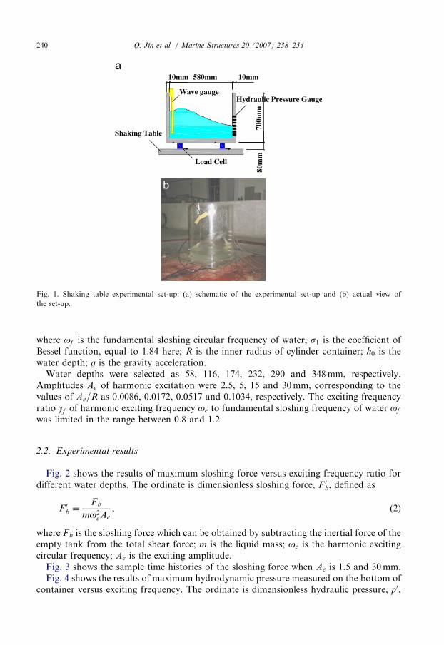
In order to investigate the possibility of using cylinder tank as TLDs, the characteristicsof the liquid sloshing has been tested for different wave height and hydrodynamic pressureunder harmonic excitation in a cylinder container. Fig. 1 shows the experimental set-up.The cylinder container with the inner diameter of D ¼ 580mm and the height of h ¼
700mm was made of organic glass. Four three-degree-of-freedom load cells with ameasurable range of 200N installed under the bottom of container were utilized to measurethe base shear in the two horizontal directions as well as to support the tank on theshaking-table surface. A wave gauge fixed on the wall of the tank was employed to measurewave height. Seven hydraulic pressure gauges with a measurable pressure range of 50 kPaand frequency range of 1000Hz were mounted on the other side of the wall at interval of5 cm to monitor the impact pressures due to the liquid sloshing. The experiments wereperformed in the shaking table at State Key Laboratory of Coastal and OffshoreEngineering, Dalian University of Technology, China.
Based on linear wave theory, the fundamental sloshing frequency of water simulatedtuned liquid in the cylinder container is given
of ¼
ffiffiffiffiffiffiffiffiffiffiffiffiffiffiffiffiffiffiffiffiffiffiffiffiffiffiffiffiffiffiffiffiffigs1R
tanhs1h0
R
� �s, (1)
ARTICLE IN PRESS
10mm 580mm 10mm
80m
m70
0mm
Wave gauge
Shaking Table
Hydraulic Pressure Gauge
Load Cell
b
Fig. 1. Shaking table experimental set-up: (a) schematic of the experimental set-up and (b) actual view of
the set-up.
Q. Jin et al. / Marine Structures 20 (2007) 238–254240
where of is the fundamental sloshing circular frequency of water; s1 is the coefficient ofBessel function, equal to 1.84 here; R is the inner radius of cylinder container; h0 is thewater depth; g is the gravity acceleration.Water depths were selected as 58, 116, 174, 232, 290 and 348mm, respectively.
Amplitudes Ae of harmonic excitation were 2.5, 5, 15 and 30mm, corresponding to thevalues of Ae=R as 0.0086, 0.0172, 0.0517 and 0.1034, respectively. The exciting frequencyratio gf of harmonic exciting frequency oe to fundamental sloshing frequency of water of
was limited in the range between 0.8 and 1.2.
2.2. Experimental results
Fig. 2 shows the results of maximum sloshing force versus exciting frequency ratio fordifferent water depths. The ordinate is dimensionless sloshing force, F 0b, defined as
F 0b ¼Fb
mo2eAe
, (2)
where Fb is the sloshing force which can be obtained by subtracting the inertial force of theempty tank from the total shear force; m is the liquid mass; oe is the harmonic excitingcircular frequency; Ae is the exciting amplitude.Fig. 3 shows the sample time histories of the sloshing force when Ae is 1.5 and 30mm.Fig. 4 shows the results of maximum hydrodynamic pressure measured on the bottom of
container versus exciting frequency. The ordinate is dimensionless hydraulic pressure, p0,

ARTICLE IN PRESS
Fig. 2. Maximum sloshing force versus exciting frequency ratio: water depth at (a) 116mm; (b) 232mm;
(c) 348 mm.
Q. Jin et al. / Marine Structures 20 (2007) 238–254 241
defined as
p0 ¼p
gwh0, (3)
where p is the hydrodynamic pressure; gw is the unit weight of water.Fig. 5 shows the results of maximum wave height versus exciting frequency in different
water depth. The ordinate is dimensionless water height, Z0, defined as
Z0 ¼Zh0
, (4)
where Z is the wave height.Based on the experimental results indicated from Figs. 3 to 5, the properties of the
sloshing water in the cylinder container can be concluded as follows:
(1)
When exciting frequency ratio gf approximately equals to unity, namely, harmonicexciting frequency is close to the fundamental sloshing frequency of water, sloshingforce reaches to maximum as well as wave height and hydraulic pressure.(2)
The dimensionless parameters F 0b, p0 and Z0 increase with the increasing of excitingamplitude.
ARTICLE IN PRESS
Fig. 3. Sample time histories of the sloshing force at Ae ¼ 2:5mm and 30mm: water depth at (a) 116mm;
(b) 232mm; (c) 348mm.
Q. Jin et al. / Marine Structures 20 (2007) 238–254242
(3)
The dimensionless parameters F 0b, p0 and Z0 decrease with the increasing of water depth. (4) When exciting amplitudes equal to 2.5 and 5mm, corresponding to the value of Ae=Ras 0.0086 and 0.0172, sloshing force as well as wave height and hydraulic pressurereduces remarkably while exciting frequency is far away from fundamental sloshingfrequency of water. When exciting amplitudes equal to 15 and 30mm, correspondingto the value of Ae=R as 0.0517 and 0.1034, sloshing force as well as wave height and

ARTICLE IN PRESS
Fig. 4. Maximum hydrodynamic pressure versus exciting frequency ratio: water depth at (a) 116mm; (b) 232mm;
(c) 348mm.
Q. Jin et al. / Marine Structures 20 (2007) 238–254 243
hydraulic pressure reduces unremarkably while exciting frequency is not much faraway from fundamental sloshing frequency of water. This illustrates a wider band ofexciting frequency ratio close to unity may also cause water sloshing response.
(5)
When exciting amplitudes equal to 2.5 and 5mm, wave surface did not break eventhough resonant condition took place, namely, gf ¼ 1:0. While exciting amplitudesequal to 15 and 30mm, larger breaking formed in the wave surface.3. Numerical analysis method on TLD
3.1. Lumped mass method by Housner
Simplified methods were proposed to simulate the behavior of TLD in finite elementmodel, including lumped mass method and linear wave theory. The lumped mass methodused in the paper has been suggested by Housner [9].
The wall of container is assumed as rigid tank for lumped mass method by Housner.Hydrodynamic pressure caused by liquid sloshing due to dynamic loadings is considered asimpulse pressure and sloshing pressure separately. The impulse pressure is proportional totank acceleration, but the direction is opposite. The sloshing pressure is related to wave

ARTICLE IN PRESS
Fig. 5. Maximum wave height versus exciting frequency ratio: water depth at (a) 116mm; (b) 232mm.
Q. Jin et al. / Marine Structures 20 (2007) 238–254244
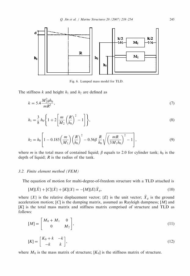
height and frequency of liquid sloshing. Thereby, both types of hydraulic pressures can besimulated by two equivalent masses linked to tank with different directions. Fig. 6 showsthe schematic of lumped mass method, in which M1 is the impulse mass fixed to tank, M2
is the sloshing mass elastically linked to tank. For cylinder tank the formulations of M1
and M2 are given by Housner:
M1 ¼ mh0ffiffiffi3p
Rtanh
ffiffiffi3p R
h0
� �, (5)
M2 ¼ m0:385R
h0tanh
1:837h0
R
� �. (6)
ARTICLE IN PRESS
Fig. 6. Lumped mass model for TLD.
Q. Jin et al. / Marine Structures 20 (2007) 238–254 245
The stiffness k and height h1 and h2 are defined as
k ¼ 5:4M2
2gh0
mR2, (7)
h1 ¼3
8h0 1þ 2
m
M2
R
h0
� �2
� 1
" #( ), (8)
h2 ¼ h0 1� 0:185m
M1
� �R
h0
� �2
� 0:56bR
h0
ffiffiffiffiffiffiffiffiffiffiffiffiffiffiffiffiffiffiffiffiffiffiffiffiffiffiffiffiffiffiffimR
3M1h0
� �2
� 1
s24
35, (9)
where m is the total mass of contained liquid; b equals to 2.0 for cylinder tank; h0 is thedepth of liquid; R is the radius of the tank.
3.2. Finite element method (FEM)
The equation of motion for multi-degree-of-freedom structure with a TLD attached is
½M�f €X g þ ½C�f _X g þ ½K �fX g ¼ �½M�fEg €X g, (10)
where fX g is the relative displacement vector; fEg is the unit vector; €X g is the groundacceleration motion; ½C� is the damping matrix, assumed as Rayleigh dampness; ½M� and½K � is the total mass matrix and stiffness matrix comprised of structure and TLD asfollows:
½M� ¼M0 þM1 0
0 M2
" #, (11)
½K � ¼K0 þ k �k
�k k
� �, (12)
where M0 is the mass matrix of structure; ½K0� is the stiffness matrix of structure.

ARTICLE IN PRESSQ. Jin et al. / Marine Structures 20 (2007) 238–254246
4. Study on controlling earthquake response based on CB32A platform
4.1. CB32A offshore jacket platform
CB32A is a four-leg jacket platform to store oil in a cylinder tank located on the top ofdeck which diameter is 15m and volume 2000m3. It is installed in Bo Sea, China with themaximum horizontal ground design acceleration of 0:220:25g as shown in Fig. 7. Theseabed elevation is �18:2m and top deck elevation þ12:5m.
4.2. Using oil tank as TLD to control earthquake response
The mechanism of controlling vibration with TLD is to dissipate the input energy by liquidsloshing and wave breaking. The fundamental sloshing frequency of liquid is required to beclose to natural frequency of structure in order to make TLD work effectively. It is of necessityto analyze the possibility of using existing oil tank on the top of CB32A platform as TLD.Dynamic loads cause the interaction between platform and liquid in the oil tank. Model offluid–solid interaction is a better way to study dynamic characteristics of platform andcontained liquid, and to validate the feasibility of Housner simplified method. By assuminginviscid, compressible and small disturbed liquid, small amplitude on the free surface of liquid,linear elastic solid, formulation of FEM based on Galerkin’s method is given
Ms 0
�Q Mf
" #€a
€p
" #þ
Ks
1
rf
Q
0 Kf
264
375 a
p
" #¼
Fs
0
� �, (13)
Fig. 7. Schematic of CB32A.

ARTICLE IN PRESSQ. Jin et al. / Marine Structures 20 (2007) 238–254 247
where p is the pressure vector at liquid nodes; a is the displacement vector at solid nodes; Qis the matrix of liquid–solid interaction; Mf and Kf are mass matrix and stiffness matrix ofliquid, respectively; Ms and Ks are the mass matrix and stiffness matrix of solid, respectively;Fs is the external force vector loading on the solid.
ADINA software was utilized for FEM analysis of platform and contained liquidinteraction. The element mesh of platform and liquid in the oil tank show in Fig. 8(a) and(b), respectively. Maximum liquid height and half of maximum liquid height in the oil tankwere analyzed, respectively. Natural frequencies of platform and contained liquid are listedin Table 1. The natural frequency ratios of platform to contained liquid by numericalanalysis are 7.37 and 4.83 at either of water depth, respectively, which are much larger thanunity. Hence, it is unfeasible to use the oil tank as TLD. Extra TLD has to be designed forthe purpose of controlling earthquake response. The error of water frequency betweennumerical analysis and Housner simplified method shown in Table 1 is allowable inengineering level. Considering the complexity and time-consuming of fluid–solidinteraction method, lumped mass method by Housner is a rapid and accurate way toanalyze practical engineering project. Thereby, Housner method is applied to the followingcontrolling earthquake analysis.
4.3. Model tests of CB32A platform with TLD
4.3.1. Experimental set-up
The model tests of CB32A platform with TLD to control earthquake response wereperformed. It is impossible to find a certain kind of model material corresponding tocontained liquid to fully satisfy the demand of time ratio in the design of controllingearthquake tests with TLD. Thus, the experimental model was designed based on thesimilarity rule that the natural frequency of model is the same as prototype one, which
Fig. 8. (a) Meshing of platform; (b) meshing of liquid in oil tank.

ARTICLE IN PRESS
Table 1
Natural frequency of platform and contained water
Liquid volume Natural frequency
of platform (Hz)
Natural frequency of contained water (Hz)
(Deviation)aFrequency
ratio
By numerical
fluid analysis
By Housner
formula
By Eq. (1)
Half of maximum
water height
1.62224 0.21988
(0%)
0.1972
(10.31%)
0.22580
(2.69%)
7.37
Maximum water
height
1.14718 0.23761
(0%)
0.2201
(7.37%)
0.24350
(2.48%)
4.83
aDeviation equals to ratio of absolute difference of water frequency by numerical analysis and water frequency
by Housner or linear wave theory to water frequency by numerical analysis.
Fig. 9. Experimental model for TLD.
Q. Jin et al. / Marine Structures 20 (2007) 238–254248
means both of frequency ratio and time ratio are unity. The scale ratio of geometry is 125.
A cylinder container, 380mm in inner diameter, to simulate TLD is made of organic glass.The size of the cylinder container is decided in order that the frequency of contained wateris close to the one of jacket platform. The model was fixed and excited in the shaking tableat State Key Laboratory of Coastal and Offshore Engineering, Dalian University ofTechnology, as shown in Fig. 9. The measurement positions are shown in Fig. 10(a)and (b).
4.3.2. Definition of ground motions
Three types of ground motions are considered here: two recorded earthquake motionsand one artificially generated earthquake motion. The first one shown in Fig. 11(a) is theNS component of El Centro ground motion, Imperial Valley 1940 earthquake. The secondone shown in Fig. 11(b) is the Tianjing ground motion, Tangshan 1976 earthquake.The third one shown in Fig. 11(c) is an artificially generated earthquake motion based on

ARTICLE IN PRESS
Tank
Accelerationtransducer
Additional weight
Accelerationtransducer
Shaking direction
Steel plate
hydraulic pressure gauges(at 2cm intervals)
Fig. 10. (a) Measurement positions on platform model; (b) view of the measurement set-up.
Fig. 11. Acceleration history curves: (a) El Centro ground motion; (b) Tianjing ground motion; (c) artificial
generated ground motion.
Q. Jin et al. / Marine Structures 20 (2007) 238–254 249
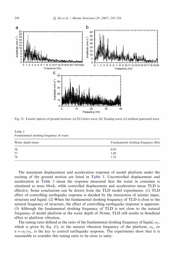
API-B response spectrum. The ground motion amplitudes are 30 gal for all of the threeinput signals. The ground motions have different frequency content as shown in theFourier transformation spectra given in Fig. 12.
4.3.3. Experimental results
The natural frequency of prototype platform is 1.17Hz from the FEM analysis, whilethe measured value of model platform is 1.20Hz from the model test. The fundamentalsloshing frequencies of three water depths from Eq. (1) are listed in Table 2. Thefundamental sloshing frequencies at depth of 57 and 76mm are closer to measured naturalfrequency of model platform.
ARTICLE IN PRESS
Fig. 12. Fourier spectra of ground motions: (a) El Centro wave; (b) Tianjing wave; (c) artificial generated wave.
Table 2
Fundamental sloshing frequency of water
Water depth (mm) Fundamental sloshing frequency (Hz)
38 0.92
57 1.09
76 1.22
Q. Jin et al. / Marine Structures 20 (2007) 238–254250
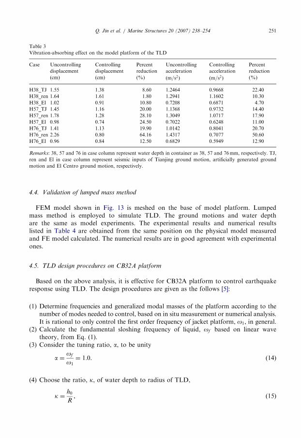
The maximum displacement and acceleration response of model platform under theexciting of the ground motion are listed in Table 3. Uncontrolled displacement andacceleration in Table 3 mean the response measured that the water in container issimulated as mass block, while controlled displacement and acceleration mean TLD iseffective. Some conclusions can be drawn from the TLD model experiments. (1) TLDeffect of controlling earthquake response is decided by the interaction of seismic input,structure and liquid. (2) When the fundamental sloshing frequency of TLD is close to thenatural frequency of structure, the effect of controlling earthquake response is apparent.(3) Although the fundamental sloshing frequency of TLD is not close to the naturalfrequency of model platform at the water depth of 38mm, TLD still results in beneficialeffect to platform vibration.The tuning ratio defined as the ratio of the fundamental sloshing frequency of liquid, of ,
which is given by Eq. (1), to the natural vibration frequency of the platform, os, ora ¼ of =os, is the key to control earthquake response. The experiments show that it isreasonable to consider this tuning ratio to be close to unity.
ARTICLE IN PRESS
Table 3
Vibration-absorbing effect on the model platform of the TLD
Case Uncontrolling
displacement
Controlling
displacement
Percent
reduction
Uncontrolling
acceleration
Controlling
acceleration
Percent
reduction
(cm) (cm) (%) ðm=s2Þ ðm=s2Þ (%)
H38_TJ 1.55 1.38 8.60 1.2464 0.9668 22.40
H38_ren 1.64 1.61 1.80 1.2941 1.1602 10.30
H38_El 1.02 0.91 10.80 0.7208 0.6871 4.70
H57_TJ 1.45 1.16 20.00 1.1368 0.9732 14.40
H57_ren 1.78 1.28 28.10 1.3049 1.0717 17.90
H57_El 0.98 0.74 24.50 0.7022 0.6248 11.00
H76_TJ 1.41 1.13 19.90 1.0142 0.8041 20.70
H76_ren 2.26 0.80 64.16 1.4317 0.7077 50.60
H76_El 0.96 0.84 12.50 0.6829 0.5949 12.90
Remarks: 38, 57 and 76 in case column represent water depth in container as 38, 57 and 76mm, respectively. TJ,
ren and El in case column represent seismic inputs of Tianjing ground motion, artificially generated ground
motion and El Centro ground motion, respectively.
Q. Jin et al. / Marine Structures 20 (2007) 238–254 251
4.4. Validation of lumped mass method
FEM model shown in Fig. 13 is meshed on the base of model platform. Lumpedmass method is employed to simulate TLD. The ground motions and water depthare the same as model experiments. The experimental results and numerical resultslisted in Table 4 are obtained from the same position on the physical model measuredand FE model calculated. The numerical results are in good agreement with experimentalones.
4.5. TLD design procedures on CB32A platform
Based on the above analysis, it is effective for CB32A platform to control earthquakeresponse using TLD. The design procedures are given as the follows [5]:
(1)
Determine frequencies and generalized modal masses of the platform according to thenumber of modes needed to control, based on in situ measurement or numerical analysis.It is rational to only control the first order frequency of jacket platform, o1, in general.(2)
Calculate the fundamental sloshing frequency of liquid, of based on linear wavetheory, from Eq. (1).(3)
Consider the tuning ratio, a, to be unitya ¼of
o1¼ 1:0. (14)
(4)
Choose the ratio, k, of water depth to radius of TLD,k ¼h0
R, (15)

ARTICLE IN PRESS
Fig. 13. Model mesh of CB32A offshore platform.
Table 4
Comparison between test data and calculate data under the earthquake motion
Seismic input Tianjing El Centro Artificially generated
Earthquake response Displacement Acceleration Displacement Acceleration Displacement Acceleration
(m) ðm=s2Þ (m) ðm=s2Þ (m) ðm=s2Þ
38 (mm) Experimental 0.0138 0.9668 0.0091 0.6871 0.0161 1.1602
Numerical 0.0130 0.9910 0.0091 0.6301 0.0150 1.0010
Deviationa (%) 5.8 2.5 0.0 8.3 6.8 13.7
57 (mm) Experimental 0.0116 0.9732 0.0074 0.6248 0.0128 1.0717
Numerical 0.0103 0.8807 0.0085 0.5323 0.0112 0.9838
Deviation (%) 11.2 9.5 14.9 14.8 12.5 8.2
76 (mm) Experimental 0.0113 0.8041 0.0084 0.5949 0.0080 0.7077
Numerical 0.0101 0.7301 0.0078 0.6203 0.0081 0.7002
Deviation (%) 10.6 9.2 7.1 4.3 1.3 1.1
aDeviation equals to ratio of absolute difference of experimental data and numerical data to experimental data.
Q. Jin et al. / Marine Structures 20 (2007) 238–254252
where h0 is the water depth of TLD; R is the radius for cylinder TLD. Then, waterdepth and radius of one tank can be obtained from Eqs. (1), (14) and (15).
(5)
Calculating the mass of water in one tank, mf , from the expression mf ¼ rpR2h0,where r is the mass density of water. Assuming mass ratio, m, defined as the ratio of the
ARTICLE IN PRESS
Table 5
The vibration-absorbing ratio of the TLD with different mass ratio
Seismic input Displacement reduction percent (%) Acceleration reduction percent (%)
m ¼ 0:5% m ¼ 1% m ¼ 3% m ¼ 0:5% m ¼ 1% m ¼ 3%
Tianjing 2.26 4.53 15.09 2.22 4.60 15.60
El Centro 5.18 10.28 17.6 3.43 5.11 11.28
Artificially generated 4.21 8.35 23.67 2.48 4.90 13.61
Q. Jin et al. / Marine Structures 20 (2007) 238–254 253
mass of total TLDs to the mass of platform, compute the N number of tanks requiredfrom N ¼ mms=mf , where ms is the mass of the platform.
(6)
Calculating earthquake response of TLD and platform system based on FEM.Return Procedure (4) to redesign if controlling earthquake response does not satisfyrequest.(7)
Design TLD system in terms of h0 and R.4.6. Controlling earthquake response analysis on CB32A platform
For CB32A platform, finite element model without TLDs, but with oil tank simulated aslumped mass method, is built. The natural frequency is 1.14Hz from modal analysis.Assuming k ¼ 0:65, water depth and radius of one TLD can be calculated as 0.455 and0.35m, respectively. The finite element model of CB32A platform is remeshed consideringjackets, deck, oil tank and TLDs simulated a lumped mass as well. The histories ofearthquake response are computed under El Centro ground motion, Tianjing groundmotion and artificially generated ground motion which amplitudes equal to 200 gal.Assuming three mass ratios, numerical results are listed in Table 5.
From Table 5, the larger the mass ratio is, the more effective the controlling earthquakeresponse is. However, the cost will increase as well.
5. Conclusions
The objective in the paper is to study the effectiveness of cylinder TLD in controllingearthquake response of jacket platform. Meanwhile, TLDs are applied to CB32A oil tankplatform to prove its feasibility.
It is effective for CB32A using TLDs to control the response due to ground motionsbased on liquid sloshing experiment, model experiment and numerical analysis. Theeffectiveness of TLD is determined by the interaction of seismic input, structure and liquid.Aiming to enhance the vibration reduction efficiency of the TLD system, the TLDfrequency is normally adjusted to be close to the frequencies of the structure and groundmotion. However, the frequency content of ground motion is abundant and complicated.Only the frequency of TLD is tuned to the frequency of structure in design, namely, tuningratio equals to be unity.
The larger the mass ratio is, the more effective the controlling earthquake response is.However, the cost will increase as well. It is economic for cost and effective for vibrationreduction that the mass ratio ranges from 1% to 5%.

ARTICLE IN PRESSQ. Jin et al. / Marine Structures 20 (2007) 238–254254
References
[1] Soong TT. State-of-the-art review: active structural control in civil engineering. Eng Struct 1988;10(2):56–64.
[2] Vancliver JK, et al. Effect of liquid storage tanks on the dynamic response of offshore platform. Appl Ocean
Res 1979;1(1):67–74.
[3] Sun LM, et al. Nonlinear waves and dynamic pressures in rectangular tuned liquid damper (TLD)—
simulation and experimental verification. JSCE J Struct Eng/Earthquake Eng 1989;6(2):251–62.
[4] Banerji P, Murudi M, et al. Tuned liquid dampers for controlling earthquake response of structures.
Earthquake Eng Struct Dyn 2000;29:587–602.
[5] Reed D, Yu J, Yeh H, Gardarsson S. Investigation of tuned liquid dampers under large amplitude excitation.
J Eng Mech 1998;124(4):405–13.
[6] Kareen A, et al. Stochastic response of structure with fluid-containing appendages. J Sound Vib
1987;119(3):389–408.
[7] Chen X, Wang LY, Xu J. TLD technique for reducing ice-induced vibration on platforms. J Cold Reg Eng
1999;13(3):139–52.
[8] Lee HN, Wong SH, Lee RS. Response mitigation on the offshore floating platform system with tuned liquid
column damper. Ocean Eng 2006;33(8–9):1118–42.
[9] Housner GW. Dynamic pressures of accelerated fluid containers. Bull Seismol Soc Am 1957;47(1):15–35.