Embed Size (px)
Citation preview
Amirkabir Journal of Mechanical Engineering
Amirkabir J. Mech. Eng., 52(8) (2020) 521-524DOI: 10.22060/mej.2019.15299.6089
Experimental and Numerical Investigation of Second Mode of Failure in Unlike End Notch Flexure Samples S. Maleki, A. Andakhshideh*, A. Seyfi
Department of Mechanical Engineering, Quchan University of Technology, Quchan, Iran
ABSTRACT: Localized lamination using composites is one of the effective solutions to repair damaged metallic pipelines. The connection of composite repair to the metal substructure in this method is one of the most important design parameters. Therefore, deriving the important parameters at the junction will help engineers in designing and predicting the interlaminar crack initiation and propagation at the composite/metal interface. In this paper, to investigate the second mode of failure in this method, the strain energy release rate is calculated experimentally and numerically in a steel/composite bond. According to an experimental standard for calculating the second mode strain energy release rate, ASTM-D7905, experimental tests are accomplished for three symmetric and asymmetric unlike end-notched flexure specimens and a relationship for the thickness of each material to have symmetric specimens is proposed. To validate the thickness calculation relationship, the finite element modeling of unlike samples using virtual crack closure technique is used which indicates the good agreement of experimental and numerical results. Comparing the experimental results showed that the strain energy release rate of symmetric samples is more than asymmetric ones and about 1.6 times as large.
Review History:
Received: 2018/11/17Revised: 2019/02/04Accepted: 2019/03/11Available Online: 2019/03/18
Keywords:
Crack propagation
Second mode of failure
Strain energy release rate
Virtual crack closure technique
Unlike end-notched flexure specimen
521
*Corresponding author’s email: [email protected]
Copyrights for this article are retained by the author(s) with publishing rights granted to Amirkabir University Press. The content of this article is subject to the terms and conditions of the Creative Commons Attribution 4.0 International (CC-BY-NC 4.0) License. For more information, please visi https://mej.aut.ac.ir/article_3343.html.
1- IntroductionThere are over 1.1 million miles of gas, petroleum, and crude oil pipelines worldwide. The corrosion of these pipelines is a significant problem, impacting both the operational safety and the economics of the pipeline. The repair methods based on bonded composite materials have recently gained popularity [1]. The connection of composite repair to the metal substructure is one of the most important design parameters. Investigating the delamination toughness and strain energy release rate of failure in the metal/composite interface can help designers in this regales. The Virtual Crack Closure Technique (VCCT) is widely used to compute the energy release rate, G, in the finite element analysis of fracture mechanics problems [2].Moura et al. [3] proposed a new data reduction scheme for measuring the critical fracture energy of adhesive joints under pure mode II loading using the End Notched Flexure (ENF) test. The method was based on the crack equivalent concept and did not require crack length monitoring during propagation. Mollón et. al. [4] carried out pure modes I and II and mixed-mode ratio tests, respectively by means of the following methods: Double Cantilever Beam (DCB), End Notch Flexure (ENF), and Asymmetric Double Cantilever Beam (ADCB). In Mollón et al. [4] the Finite Element Method (FEM) was used to analyze the stress state ahead of the crack to better explain the fracture micromechanisms
acting under different loading modes and their influence on delamination fracture toughness.in this paper, the interlaminar strain energy release rate is calculated experimentally and numerically in a steel/composite bond. ASTM-D7905 [5], is an experimental standard for calculating the strain energy release rate in the second mode of failure for symmetric end-notched flexure specimens. In this paper, due to the unlike of the upper and lower beams, first, the relationships for the thickness calculation of composite and steel beams to have symmetric samples is obtained and experimental tests are carried out. Next, the finite element modeling of unlike samples using virtual crack closure method is applied to validate thickness calculation relationship which indicates its accuracy.
2- Experimental Procedure
2- 1- The thickness of steel and composite beams in unlike end-notched flexure specimen To find relationships for thickness ratio of steel and composite, the curvature radius of beams is assumed to be equal. We have,
(1)( )21 12 23
2 21 2 12 2
1comp st
st
h E Eh E E E
υ υ
υ
−=
−Where, comph is composite thickness, sth , steel thickness,
stE , elasticity module of steel, 1 2,E E , elasticity module of
S. Maleki et al., Amirkabir J. Mech. Eng., 52(8) (2020) 521-524, DOI: 10.22060/mej.2019.15299.6089
522
composite in 1,2 directions and 21 12,υ υ are possession ratios of the composite.
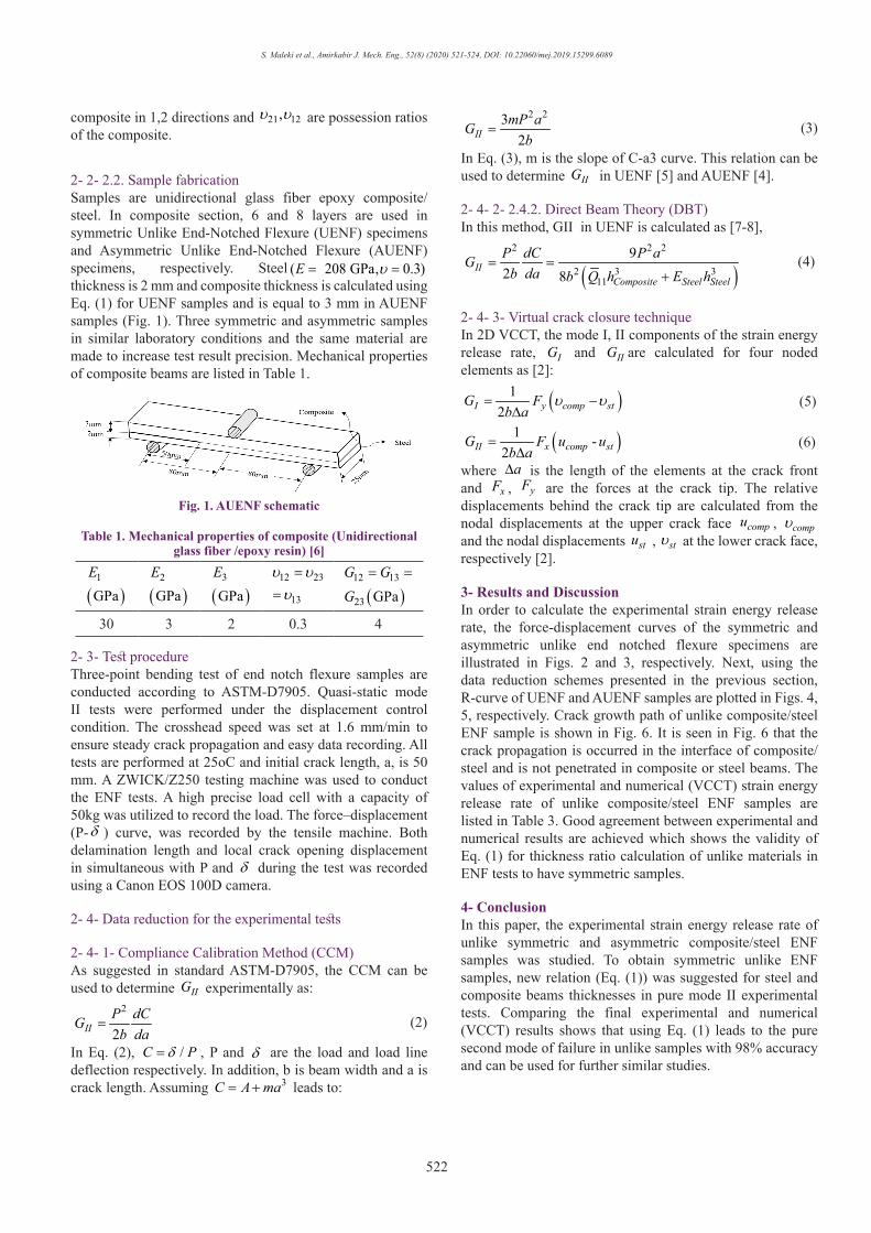
2- 2- 2.2. Sample fabricationSamples are unidirectional glass fiber epoxy composite/steel. In composite section, 6 and 8 layers are used in symmetric Unlike End-Notched Flexure (UENF) specimens and Asymmetric Unlike End-Notched Flexure (AUENF) specimens, respectively. Steel ( 208 GPa, 0.3)E υ= =thickness is 2 mm and composite thickness is calculated using Eq. (1) for UENF samples and is equal to 3 mm in AUENF samples (Fig. 1). Three symmetric and asymmetric samples in similar laboratory conditions and the same material are made to increase test result precision. Mechanical properties of composite beams are listed in Table 1.
Fig. 1. AUENF schematic
Table 1. Mechanical properties of composite (Unidirectional glass fiber /epoxy resin) [6]
( )1
GPaE
( )2
GPaE
( )3
GPaE 12 23
13
υ υυ=
= ( )12 13
23 GPaG GG
= =
30 3 2 0.3 4
2- 3- Test procedureThree-point bending test of end notch flexure samples are conducted according to ASTM-D7905. Quasi-static mode II tests were performed under the displacement control condition. The crosshead speed was set at 1.6 mm/min to ensure steady crack propagation and easy data recording. All tests are performed at 25oC and initial crack length, a, is 50 mm. A ZWICK/Z250 testing machine was used to conduct the ENF tests. A high precise load cell with a capacity of 50kg was utilized to record the load. The force–displacement (P-δ ) curve, was recorded by the tensile machine. Both delamination length and local crack opening displacement in simultaneous with P and δ during the test was recorded using a Canon EOS 100D camera.
2- 4- Data reduction for the experimental tests
2- 4- 1- Compliance Calibration Method (CCM)As suggested in standard ASTM-D7905, the CCM can be used to determine IIG experimentally as:
(2)2
2IIP dCG
b da=
In Eq. (2), /C Pδ= , P and δ are the load and load line deflection respectively. In addition, b is beam width and a is crack length. Assuming 3C A ma= + leads to:
(3)2 23
2IImP aG
b=
In Eq. (3), m is the slope of C-a3 curve. This relation can be used to determine IIG in UENF [5] and AUENF [4].
2- 4- 2- 2.4.2. Direct Beam Theory (DBT)In this method, GII in UENF is calculated as [7-8],
(4)
( )2 2 2
2 3 311
92 8
IIComposite Steel Steel
P dC P aGb da b Q h E h
= =+
2- 4- 3- Virtual crack closure techniqueIn 2D VCCT, the mode I, II components of the strain energy release rate, IG and IIG are calculated for four noded elements as [2]:
(5)( )12I y comp stG Fb a
υ υ= −∆
(6)( )1 -2II x comp stG F u ub a
=∆
where a∆ is the length of the elements at the crack front and xF , yF are the forces at the crack tip. The relative displacements behind the crack tip are calculated from the nodal displacements at the upper crack face compu , compυ and the nodal displacements stu , stυ at the lower crack face, respectively [2].
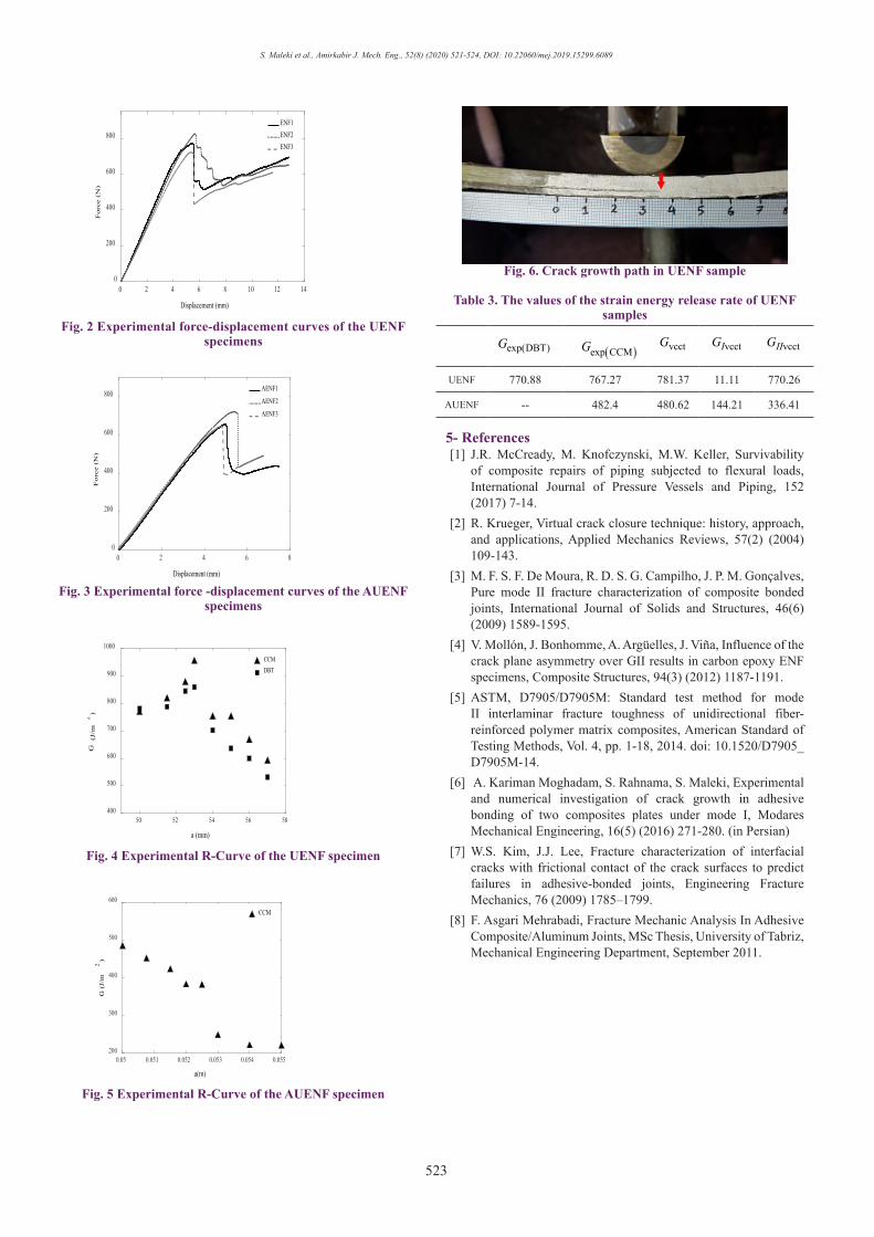
3- Results and DiscussionIn order to calculate the experimental strain energy release rate, the force-displacement curves of the symmetric and asymmetric unlike end notched flexure specimens are illustrated in Figs. 2 and 3, respectively. Next, using the data reduction schemes presented in the previous section, R-curve of UENF and AUENF samples are plotted in Figs. 4, 5, respectively. Crack growth path of unlike composite/steel ENF sample is shown in Fig. 6. It is seen in Fig. 6 that the crack propagation is occurred in the interface of composite/steel and is not penetrated in composite or steel beams. The values of experimental and numerical (VCCT) strain energy release rate of unlike composite/steel ENF samples are listed in Table 3. Good agreement between experimental and numerical results are achieved which shows the validity of Eq. (1) for thickness ratio calculation of unlike materials in ENF tests to have symmetric samples.
4- ConclusionIn this paper, the experimental strain energy release rate of unlike symmetric and asymmetric composite/steel ENF samples was studied. To obtain symmetric unlike ENF samples, new relation (Eq. (1)) was suggested for steel and composite beams thicknesses in pure mode II experimental tests. Comparing the final experimental and numerical (VCCT) results shows that using Eq. (1) leads to the pure second mode of failure in unlike samples with 98% accuracy and can be used for further similar studies.
S. Maleki et al., Amirkabir J. Mech. Eng., 52(8) (2020) 521-524, DOI: 10.22060/mej.2019.15299.6089
523
0 2 4 6 8 10 12 14
Displacement (mm)
0
200
400
600
800
Forc
e (N
)
ENF1ENF2ENF3
Fig. 2 Experimental force-displacement curves of the UENF specimens
0 2 4 6 8
Displacement (mm)
0
200
400
600
800
Forc
e (N
)
AENF1
AENF2
AENF3
Fig. 3 Experimental force -displacement curves of the AUENF specimens
50 52 54 56 58
a (mm)
400
500
600
700
800
900
1000
G (
J/m
2)
CCMDBT
Fig. 4 Experimental R-Curve of the UENF specimen
0.05 0.051 0.052 0.053 0.054 0.055
a(m)
200
300
400
500
600
G (
J/m
2)
CCM
Fig. 5 Experimental R-Curve of the AUENF specimen
Fig. 6. Crack growth path in UENF sample
Table 3. The values of the strain energy release rate of UENF samples
vcctIIGvcctIGvcctG( )exp CCMGexp(DBT)G
770.2611.11781.37767.27770.88UENF
336.41144.21480.62482.4--AUENF
5- References [1] J.R. McCready, M. Knofczynski, M.W. Keller, Survivability
of composite repairs of piping subjected to flexural loads, International Journal of Pressure Vessels and Piping, 152 (2017) 7-14.
[2] R. Krueger, Virtual crack closure technique: history, approach, and applications, Applied Mechanics Reviews, 57(2) (2004) 109-143.
[3] M. F. S. F. De Moura, R. D. S. G. Campilho, J. P. M. Gonçalves, Pure mode II fracture characterization of composite bonded joints, International Journal of Solids and Structures, 46(6) (2009) 1589-1595.
[4] V. Mollón, J. Bonhomme, A. Argüelles, J. Viña, Influence of the crack plane asymmetry over GII results in carbon epoxy ENF specimens, Composite Structures, 94(3) (2012) 1187-1191.
[5] ASTM, D7905/D7905M: Standard test method for mode II interlaminar fracture toughness of unidirectional fiber-reinforced polymer matrix composites, American Standard of Testing Methods, Vol. 4, pp. 1-18, 2014. doi: 10.1520/D7905_D7905M-14.
[6] A. Kariman Moghadam, S. Rahnama, S. Maleki, Experimental and numerical investigation of crack growth in adhesive bonding of two composites plates under mode I, Modares Mechanical Engineering, 16(5) (2016) 271-280. (in Persian)
[7] W.S. Kim, J.J. Lee, Fracture characterization of interfacial cracks with frictional contact of the crack surfaces to predict failures in adhesive-bonded joints, Engineering Fracture Mechanics, 76 (2009) 1785–1799.
[8] F. Asgari Mehrabadi, Fracture Mechanic Analysis In Adhesive Composite/Aluminum Joints, MSc Thesis, University of Tabriz, Mechanical Engineering Department, September 2011.

This pa
ge in
tentio
nally
left b
lank