Embed Size (px)
Citation preview

7/28/2019 Experimental and Computational Study of a Micro Vertical Axis Wind
http://slidepdf.com/reader/full/experimental-and-computational-study-of-a-micro-vertical-axis-wind 1/9
Procedia Engineering 49 (2012) 254 – 262
1877-7058 © 2012 The Authors. Published by Elsevier Ltd. Selection and/or peer-review under responsibility of the International Energy Foundation
doi:10.1016/j.proeng.2012.10.135
Evolving Energy-IEF International Energy Congress (IEF-IEC2012)
Experimental and Computational Study of a Micro Vertical Axis Wind
Turbine
Abdulkadir Ali*,a, Steve Golde
b, Firoz Alam
a, and Hazim Moria
a
aSchool of Aerospace, Mechanical and Manufacturing Engineering, RMIT University,
Plenty Road, Bundoora, Melbourne, VIC 3083, AustraliabWind Energy Technology Pty Ltd, Bobbin Head Road, Sydney, NSW 2074, Australia
Elsevier use only: Revised 30th August 2012; accepted 31st August 2012
Abstract
With recent surge in fossil fuel prices and demand for cleaner renewable energy sources, wind turbines have become an alternative
technology for power generation. Greenhouse gases such as carbon dioxide (CO2) emitted into the atmosphere contribute to the global
climate change. This paper investigates the design of a Savonius type vertical axis wind turbine and its potential to generate power. To
enhance the performance of the turbine, a flow restricting cowl is incorporated into the turbine. The airflow behavior of the turbine was
investigated both experimentally and computationally. Three different configurations were studied (open position, centred position and a
closed position). It is found that a partially cowled turbine in a centred and closed position resulted in a better performance of the turbine
than a fully cowled turbine with the same configuration.
© 2012 The Authors. Published by Elsevier Ltd. Selection and/or peer-review under responsibility of International Energy
Foundation.
Keywords: Cowling; Wind tunnel; CFD; Wind turbine; Savonius; VAWTs; HAWTs
Nomenclature
V Velocity
A Area
m Mass
P Power Density
VAWT Vertical Axis Wind TurbineHAWT Horizontal Axis Wind Turbine
CFD Computational Fluid Dynamics
CO2 Carbon Dioxide
* Corresponding author. Tel.: +61 3 9925 6103; fax: +61 3 9925 6108.
E-mail address: [email protected]
Available online at www.sciencedirect.com
© 2012 The Authors. Published by Elsevier Ltd. Selection and/or peer-review under responsibility of the International Energy Foundation

7/28/2019 Experimental and Computational Study of a Micro Vertical Axis Wind
http://slidepdf.com/reader/full/experimental-and-computational-study-of-a-micro-vertical-axis-wind 2/9
255 Abdulkadir Ali et al. / Procedia Engineering 49 (2012) 254 – 262
1. Introduction
Wind energy is fast becoming an alternative source of energy to generate power. With the current state of the world
development, our demand for energy has increased exponentially and as a result, more fossil fuel such as coal are burnt
resulting in CO2 emissions into the atmosphere. The emission of CO2 into the atmosphere contributes to the global climate
change. To tackle this problem, many of the developed nations are continuing to invest heavily in renewable energy sources.
As part of the global CO2 emission reduction strategy, Australia has developed policies to generate power from renewableenergy of at least 20% by the year 2020 [1].
Harnessing the energy of the wind is a clean and reliable way of reducing our dependency on fossil fuel thereby
decreasing the CO2 emission into the atmosphere. Wind turbines allow the conversion of wind energy to kinetic energy for
electricity generation. While there are currently a range of wind turbines being used for power generation, the bulk of these
wind turbines are extremely large and used for large scale power producing (up to 4 MW) [2]. These large wind turbines are
required to be placed in non-populated areas where there is minimal flow disturbance from nearby objects as well as tominimise discomfort to surrounding dwellings. The type of wind turbines available today, the horizontal axis wind turbine
(HAWT) is the most common type of wind turbine both commercially and domestically [3]. The geometrical shape and
size of the blades are very critical as they ultimately determine the amount of energy that can be extracted from the wind.
Unlike HAWTs, which requires a yaw mechanism to align itself at the direction of the wind, vertical axis wind turbines
(VAWTs) are less sensitive to a change in wind direction. This is particularly an important advantage for the effective use
of VAWTs in urban and suburban environments [4]. VAWTs are typically classified into two categories: a Darrieus and aSavonius. A Darrieus turbine rotor relies on lift to generate torque, whereas a Savonius turbine rotor relies on drag. Both of this type design have a single purpose that is to, generate power [5]. Regardless of the type of wind turbine, the main goal of
a wind turbine is to extract as much energy as possible from the wind. Every object, including air, in motion will have some
sought of kinetic energy. The kinetic energy of air passing through the turbines is converted into mechanical energy and
ultimately into electrical energy. To determine the amount of power available in the wind, the following equations are used.
2
2
1V m E
K (1)
V Am (2)
Substituting Eq. (2) into Eq. (1), the idealized equation for power generated from wind by the turbine is obtained as shownin Eq. (3):
3
2
1V A P (3)
The maximum theoretical coefficient of performance or otherwise known as Betz limit is defined as 16/27 or 0.59 [6]. What
this actually means is that for any given wind turbine, the maximum energy it can extract from the wind is 59 per cent of the
winds energy. In practice however, the best modern wind turbine can achieve a coefficient of performance of about 40 per
cent. This is the maximum value, achievable over a narrow band of wind speeds. The actual coefficient of performance willvary with wind speeds.
Small scale wind turbines can generate electricity for households and in turn reduce the power bill and carbon footprint.
However, a residential wind turbine needs to be small and inexpensive to mount and install as well as to operate efficiently.
The small scale wind turbine can be installed on roofs of houses and on buildings [7]. It is well known that there are a large
number of small scale wind turbines in the market that can be implemented in a domestic environment, however, their
power generation efficiencies are questionable. Small scale wind turbines face complex wind conditions at the height atwhich they operate. Due to the complexity of wind conditions in built up areas, where the atmospheric wind is highly
turbulent, small wind turbines need a smart design that can operate more efficiently and generate more power at low wind
speeds.
A major disadvantage for VAWTs is that, as the airflow moves through the rotor, it has to come in to contact with the
rotating blades as it exits the rear. This creates a negative torque on the rotor and the exiting air stream is directed back in tothe incoming free stream. A turbulent region is produced due to the interaction of the exiting air stream and incoming free
stream which not only introduces losses minimising efficiency, but also creates a pressure fluctuations that produce
vibrations in the turbine [8]. This unstable flow restricts the rotor from accelerating to higher torque producing speeds. In
order for VAWTs to extract maximum energy and reduces losses due to turbulence, it is important to have a good
understanding of the flow behaviour on VAWTs. Several flow enhancing devices have been proposed in the past to
minimise the airflow on the non-torque side of the rotor and the majority of them a have proven to be ineffective as they

7/28/2019 Experimental and Computational Study of a Micro Vertical Axis Wind
http://slidepdf.com/reader/full/experimental-and-computational-study-of-a-micro-vertical-axis-wind 3/9
256 Abdulkadir Ali et al. / Procedia Engineering 49 (2012) 254 – 262
have the adverse effect of causing a high pressure zone and very little additional air is directed onto the actual rotor.
In this paper, we propose a new concept of vertical axis wind turbine that can generate more power under turbulent wind
environment. To reduce the turbulence of the VAWTs we propose simultaneously shielding parts of the rotor from the wind,
whilst directing to those parts where it can more efficiently impart momentum to the rotor.
Figure 1 shows a new vertical axis wind turbine with cowling concept that can potentially extract more power from the wind
and on the trailing blades of a vertical axis wind turbine and allow for higher resultant torques produced by the wind turbine
(a) (b)
Fig.1. (a) Concept cowling; (b) Cross section of the wind turbine and visualization of the flow direction
The concept of cowling, developed by Wind Energy Technology Pty Ltd Australia, incorporates an outer cowling with a tail
section. The tail section of the outer cowling allows even flow over both sides of the cowling when the cowling is in linewith the airflow. When the cowling is not in line with the airflow there will be a pressure differential between the two sides
of the turbine cowling, and if the cowling is mounted on a bearing, the cowling will yaw to an in line with the flow position.
The concept cowling also incorporates a vent tube in the center of the turbine rotor and an induction chimney. The inner vent tube has the main purpose of allowing the flow over the turbine blades and to recirculate the flow in the turbine as seen
in Figure 1 (b). The chimney is one of the critical features of the cowling. The main purpose of the chimney is to allow the
airflow to exit the cowling. The secondary effect of the chimney is to create a pressure differential in the vent tube andinduce a flow swirling in the middle of the turbine. This flow swirling induces a flow rotation which will create a low
pressure at the entrance to the vent tube and from this increase the driving force of the turbine. The primary objective of this
paper is to undertake an experimental and computational investigation of the concept and explore its potential for power generation.
2. Methodology
2.1. Wind Tunnel Test
To investigate the concept of cowling, a wind tunnel test was conducted at RMIT University industrial wind tunnel. The
wind tunnel was used to evaluate the performance of the wind turbine over a range of wind speeds. The data obtained from
these tests would determine if a flow restricting device improves the performance of a wind turbine and at which speeds the
turbines operate most efficiently and can provide data that would allow the optimisation. Three configurations have been
tested. These configurations are:a) Bare rotor (no cowl)
b) Cowled with no induction vent tube
c) Fully cowled
The bare rotor is the control configuration for benchmarking. The bare rotor is not cowled and has no features that would
enhance or degrade the performance of the turbine. The results obtained from the testing of this configuration were used to
determine whether the other configurations would have a positive or negative effect on the performance. The second

7/28/2019 Experimental and Computational Study of a Micro Vertical Axis Wind
http://slidepdf.com/reader/full/experimental-and-computational-study-of-a-micro-vertical-axis-wind 4/9
257 Abdulkadir Ali et al. / Procedia Engineering 49 (2012) 254 – 262
configuration to be tested is the cowled configuration without induction vent tube. This configuration consists of a turbine
rotor being covered only by the external wall of the cowl which should allow large amounts of flow to circulate within the
cowling. This configuration is not a part of the induction chimney and would allow to determine if the induction chimney
and flow restricting vent tube have a major effect on the performance of the prototype wind turbine. The last major
configuration is the fully cowled configuration. The Fully cowled configuration consists of external cowling walls,induction vent tube and chimney. The tail section would allow the testing of the pivot feature of the turbine. The testing of
all three configurations allows the performance increase or decrease caused by separate cowling features.
Fig.2. Test configurations
During the testing, the orientation of the cowling was considered. The cowling utilises a 90° opening to restrict flow over
the turbine rotor. Depending on the orientation of the cowling the airflow can be directed over the driving more than the
forward moving blades or oppositely over the forward moving blades that causes high resistance. As the turbine cowl is
designed to pivot in the wind it is was decided to test different opening positions to determine the best possible opening position with respect to the airflow that would result in a better performance of the wind turbine. The closed position was
expected to direct flow predominantly over the driving blades and should reduce any back flow over the forward moving
blades that would cause resistance. The closed position should however allow less flow over the entire rotor then any of the
other positions. The centred position was used for the main flow entrance position of the turbine cowl. This position should
allow a large air flow over the driving section of the turbine, while it is expected to reduce flow over the forward moving,
resistance producing blades. The open position should allow the largest possible airflow over the turbine rotor; however this position is most likely to have high flows over the forward moving blades which should result in a high drag on the turbine
rotor. While the drag load has the potential to be high the potential for high flows over the driving turbine blades could be
large enough to drive the rotor.
Figure 3 shows the experimental setup of the wind turbine in RMIT University wind tunnel at zero degree yaw angle. The
full scale turbine was tested for wind speeds up to 30km/h. The initial wind speed at which the turbine began to rotate wasrecorded. It was noted during the test that, if the wind tunnel speed was reduced, the rotor would continue to spin at lower
wind speeds than which it began to rotate initially.

7/28/2019 Experimental and Computational Study of a Micro Vertical Axis Wind
http://slidepdf.com/reader/full/experimental-and-computational-study-of-a-micro-vertical-axis-wind 5/9
258 Abdulkadir Ali et al. / Procedia Engineering 49 (2012) 254 – 262
Fig.3. Wind turbine prototype made from stainless steel.
2.2 Computational modelling
Computational Fluid Dynamics (CFD) modeling is a common practice in engineering to understand airflow behaviour
around an object. To aid this investigation, CFD modeling was undertaken to understand the airflow velocities and air pressure distribution around the turbines. The turbine model varies from the full scale wind tunnel tested model in several
ways. The main critical difference is that the CFD model has a very small clearance (less than 1mm) between the edges of the turbine blades and the cowling walls. Because of this there is less flow through the turbine than that of the real model.
While this is a major difference, the small wall clearance coincides with the ideas and concepts when the turbine as initially
designed. Because of this the CFD is valid for a proof of concept and will also allow the concept to be simulated in its most
idealised state. Another major point that needs to be noted is that the airflow over the turbine is modelled to be for one
particular wind speed of 36km/h and the turbine is specified to be spinning at a constant revolution per minute (RPM) of
100. This will allow the flow to be visualised for a particular case and allow of a general idea to be formed about the flowthrough the turbine, however the flow pattern is expected to vary with wind speed and RPM. The CFD analysis is used for
comparison purpose.
3. Results
3.1 Full Scale Prototype
Full scale prototype made of stainless steel was manufactured. The turbine configurations results were compared to each
other with respect to the cowling inlet positions. The cowling inlet position is used to separate the comparisons as each
position would allow a different mass flow through the turbine rotor and a varying potential energy of the turbine. Each position is compared to the bare rotor configuration to validate the effect of a cowl. Therefore all results were compared to
the uncowled configuration to determine the effect of the cowl.

7/28/2019 Experimental and Computational Study of a Micro Vertical Axis Wind
http://slidepdf.com/reader/full/experimental-and-computational-study-of-a-micro-vertical-axis-wind 6/9
259 Abdulkadir Ali et al. / Procedia Engineering 49 (2012) 254 – 262
Fig.4. Comparison of configurations for centred position.
It can be seen from Figure 4 that the highest RPMs are reached by the bare rotor and that the fully cowled configurationdoes not allow rotation. The partially cowled configuration generates rotational speeds that are close to that of the bare rotor
for wind speeds of 15km/h and 20km/h, but after that it begins to drop off. It can also be seen that the bare rotor is
significantly more effective at wind speeds below the 15km/h. Overall it can be said that the best performance was achieved
by the bare rotor for the centred position over the entire range of wind speeds. At 15km/h wind speed, the rotational speedof the partially cowled turbine configuration had slightly higher rotational speeds than fully closed configuration. The
rotational behaviour of these two configurations was considered to be very similar.
Fig.5. Comparison of configurations for open position.
For the open position, neither partially cowled nor fully cowled configurations produce any rotational motion due to the
restricted flow over the turbine. The design of the cowl should allow self-alignment with the wind direction in order to
increase the rotational speeds.
Figure 6 shows that the bare rotor is most efficient configuration as no rotational motion was noted below 15 km/h under
partially and fully cowled closed positions. The fully cowled turbine started rotating at speeds over 20 km/h. The frequencyof rotational motion is still lower than frequencies of partially cowled and the bare rotor configurations. At wind speeds

7/28/2019 Experimental and Computational Study of a Micro Vertical Axis Wind
http://slidepdf.com/reader/full/experimental-and-computational-study-of-a-micro-vertical-axis-wind 7/9
260 Abdulkadir Ali et al. / Procedia Engineering 49 (2012) 254 – 262
exceeding 20 km/h, no variation in RPM readings for the partially cowled turbine and bare rotor was observed (Figure 6).
Fig.6. Comparison of configurations for closed position.
3.2 Small Scale Prototype
A small scale prototype wind turbine was manufactured using cardboard. This prototype is significantly lighter and smaller
than the stainless steel made prototype. The cardboard made prototype has less inertia compared to the steel prototype. It is
expected that the cardboard made prototype will start rotating at lower wind speeds. The prototype is shown in Figure 7.
The cardboard model was tested under a range of wind speeds. However, the maximum speed was restricted due to the
The results obtained from the wind tunnel showed that the bare rotor started rotating at very low wind speed (below 1 m/s).
The rotational speed was almost linearly increased at wind speeds 10 m/s and above. In contrast, the rotational speed
increased significantly when the cowl was introduced. As shown in Figure 8, the rotation speed of the turbine with cowl wasincreased at speeds tested and the variation in RPM is more than doubled.
Fig.7. Wind turbine made from cardboard.

7/28/2019 Experimental and Computational Study of a Micro Vertical Axis Wind
http://slidepdf.com/reader/full/experimental-and-computational-study-of-a-micro-vertical-axis-wind 8/9
261 Abdulkadir Ali et al. / Procedia Engineering 49 (2012) 254 – 262
Fig. 8. Wind tunnel results for bare rotor and cowling wind turbine.
2.2 Computational Modelling
The computational modelling of the wind turbine was undertaken to determine and visualise the airflow direction,
pressure contours and velocity profiles. At first the flow through the bare rotor was modelled. In the modelling, the rotor
was purely exposed to the oncoming airflow and no restriction was applied to it. A single reference frame condition was
applied for this analysis in order to predict the flow behaviour. The model geometry is based on cardboard prototype model.
The static pressure distributions on the bare rotor and the cowl are shown in Figures 9 and 10 respectively. The simulated
results indicate that there is significant variation in static pressure distribution in and around the blades. The variation is
especially larger between front and rear blades. The variation of pressure difference is causing the rotational motion of the
rotor.
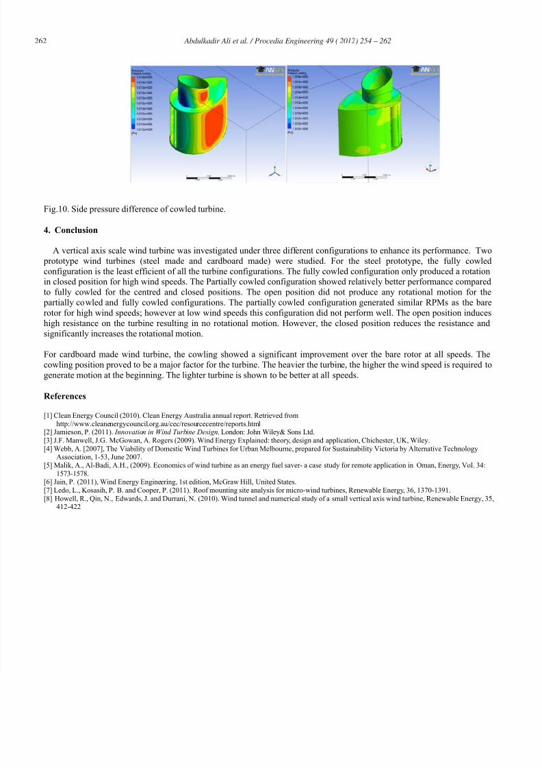
Figure 10 shows the static pressure distribution on the cowl surface. One side of the cowl experiences higher pressure than
the other side resulting in the self-regulated alignment of the cowl with the wind direction. Blades near the opening of thecowl are exposed to low pressure zone thus allowing higher air velocity through the opening which drives the blades. The
blades at the rear do not experience any resistive air pressure. As a result, they need to perform significantly less work.
Fig.9. Pressure distribution around the blades.
7/28/2019 Experimental and Computational Study of a Micro Vertical Axis Wind
http://slidepdf.com/reader/full/experimental-and-computational-study-of-a-micro-vertical-axis-wind 9/9
262 Abdulkadir Ali et al. / Procedia Engineering 49 (2012) 254 – 262
Fig.10. Side pressure difference of cowled turbine.
4. Conclusion
A vertical axis scale wind turbine was investigated under three different configurations to enhance its performance. Two
prototype wind turbines (steel made and cardboard made) were studied. For the steel prototype, the fully cowled
configuration is the least efficient of all the turbine configurations. The fully cowled configuration only produced a rotationin closed position for high wind speeds. The Partially cowled configuration showed relatively better performance compared
to fully cowled for the centred and closed positions. The open position did not produce any rotational motion for the
partially cowled and fully cowled configurations. The partially cowled configuration generated similar RPMs as the bare
rotor for high wind speeds; however at low wind speeds this configuration did not perform well. The open position induces
high resistance on the turbine resulting in no rotational motion. However, the closed position reduces the resistance and
significantly increases the rotational motion.
For cardboard made wind turbine, the cowling showed a significant improvement over the bare rotor at all speeds. The
cowling position proved to be a major factor for the turbine. The heavier the turbine, the higher the wind speed is required to
generate motion at the beginning. The lighter turbine is shown to be better at all speeds.
References
[1] Clean Energy Council (2010). Clean Energy Australia annual report. Retrieved from
http://www.cleanenergycouncil.org.au/cec/resourcecentre/reports.html[2] Jamieson, P. (2011). Innovation in Wind Turbine Design, London: John Wiley& Sons Ltd.
[3] J.F. Manwell, J.G. McGowan, A. Rogers (2009). Wind Energy Explained: theory, design and application, Chichester, UK, Wiley.
[4] Webb, A. [2007], The Viability of Domestic Wind Turbines for Urban Melbourne, prepared for Sustainability Victoria by Alternative TechnologyAssociation, 1-53, June 2007.
[5] Malik, A., Al-Badi, A.H., (2009). Economics of wind turbine as an energy fuel saver- a case study for remote application in Oman, Energy, Vol. 34:
1573-1578.[6] Jain, P. (2011), Wind Energy Engineering, 1st edition, McGraw Hill, United States.
[7] Ledo, L., Kosasih, P. B. and Cooper, P. (2011). Roof mounting site analysis for micro-wind turbines, Renewable Energy, 36, 1370-1391.
[8] Howell, R., Qin, N., Edwards, J. and Durrani, N. (2010). Wind tunnel and numerical study of a small vertical axis wind turbine, Renewable Energy, 35,412-422