Embed Size (px)
Citation preview
EXPERIMENTAL ANALYSIS OF STRUCTURAL
COMPATIBILITY AT THE INTERFACE BETWEEN
ASPHALT CONCRETE PAVEMENTS AND
ORTHOTROPIC STEEL DECK SURFACES
by
Edoardo Bocci (corresponding author)
Ph.D. Student
Dipartimento di Ingegneria Civile, Edile e Architettura
Università Politecnica delle Marche
Via Brecce Bianche
60131 Ancona (Italy)
Tel: +39 (0) 71 220 45 07
Fax: +39 (0) 71 220 45 10
Email: [email protected]
Francesco Canestrari Full Professor
Dipartimento di Ingegneria Civile, Edile e Architettura
Università Politecnica delle Marche
Via Brecce Bianche
60131 Ancona (Italy)
Tel: +39 (0) 71 220 45 07
Fax: +39 (0) 71 220 45 10
Email: [email protected]
Word Count: Text 3,956 words + 2 Tables (500 words) + 6 Figures (1500 words)
Paper submitted for the TRB 91st Annual Meeting
Washington DC, Jan 22-26th, 2012
TRB 2012 Annual Meeting Paper revised from original submittal.
ABSTRACT 1
2 Steel orthotropic deck is the most suitable solution for long-span bridges in virtue of its low 3 weight and good mechanical properties. However it shows a lack of adhesion with ordinary 4 paving materials and for this reason special bonding coats are usually applied on the steel 5 surface. Polymer-modified bitumen, asphalt-based mastic, epoxy asphalt and reinforced 6 asphalt membrane have all been used at the interface between the hot mix asphalt (HMA) 7 course and steel bridge decks. A description of these materials and their construction process 8 is provided. In some extreme situations even mechanical reinforcement is necessary to 9 provide adequate bonding between the steel deck and the asphalt pavement. 10 The aim of this experimental study was the laboratory evaluation of the shear properties of 11 smooth and reinforced steel interfaces coated with a polymer-modified bitumen between the 12 steel deck and the conventional HMA. A suitable specimen preparation procedure was 13 preliminarily defined. The shear resistance was evaluated using the ASTRA shear test device 14 in order to investigate the effects of temperature and normal stress on different types of 15 HMA-steel interfaces. 16 The results showed that reinforced steel interfaces guarantee higher performance than smooth 17 interfaces, especially with increasing temperature. Thus reinforced steel interfaces can be 18 considered as a reliable solution in case of high shear traffic-induced stresses. 19 20
21
TRB 2012 Annual Meeting Paper revised from original submittal.
INTRODUCTION 22 23 The number of steel orthotropic bridges designed and built all over the world has 24 rapidly increased during recent years. Thanks to weight reductions that allow up to 20% of 25 the total bridge mass to be saved (1), this type of construction represents the best design 26 solution for long-span bridges. The Akashi-Kaikyō Bridge (Japan), which is the bridge with 27 the longest span, the Millau Viaduct (France), which is currently the tallest bridge in the 28 world, the Golden Gate Bridge (United States) and the three Santiago Calatrava Bridges in 29 Reggio Emilia (Italy) are important examples of the orthotropic deck structural solution. 30 One of the most critical problems with steel bridges is the poor bonding of the paving 31 materials with the deck surface, that can be subject to early damage, as shown by Wang et al. 32 (2). Consequently, driving can be uncomfortable and dangerous, and the cracks in the 33 pavement may represent a preferential way to the steel deck for corrosive agents. 34 The problem of adhesion at the interface with upper asphalt layer is also a concern 35 with cement concrete decks. Leng et al. (3, 4) accurately studied the interface bonding 36 between hot-mix asphalt and portland cement concrete in order to determine the most suitable 37 materials and procedures for the improvement of the shear strength. 38 As in the case of cement concrete bridges, the most widespread solution for steel 39 decks is the application of a bond coat on the steel surface in order to provide both 40 waterproofing and adhesion with the asphalt pavement (5). On the international market there 41 are many materials that accomplish this task, such as polymer-modified bitumens (PmBs), 42 mastic asphalt, epoxy or epoxy-polyurethane resins, asphalt multilayer membranes. 43 However there are some situations, for example small-radius curves or steep slopes, 44 where even the best bond coat does not manage to withstand the high tangential stresses 45 exerted at the steel-asphalt concrete interface. In these cases an effective solution consists in 46 welding mechanical reinforcements to the steel surface after the deck has already been in 47 place. These steel elements may be, for example, electrowelded nets, linear or L-shaped 48 transversal bars, vertical spikes. When steel elements are used, as in the case of geogrid 49 reinforcement in traditional flexible pavements (6), the shear response does not depend on the 50 interface behavior but on the physical properties of the entire interlayer, because the 51 mechanical stresses affect a relevant thickness of the steel-asphalt system. 52 The main problem with this solution is related to the logistics of field installation. 53 Immediately after steel deck sandblasting, the welding of the reinforcement and the 54 application of the bonding coat must be very quick in order to avoid early corrosion. For this 55 reason the electrowelded net is preferable instead of other reinforcement, because it can be 56 applied to the deck with fewer welding spots. 57 The present work studied the adhesive properties between asphalt concrete and steel 58 for smooth, net-reinforced and bar-reinforced interfaces. The slipping resistance of steel–59 asphalt concrete double-layered specimens was evaluated using the ASTRA Shear Test 60 Device in order to investigate the effect of temperature and normal stress on different types of 61 reinforced steel interfaces. 62 63
64
TRB 2012 Annual Meeting Paper revised from original submittal.
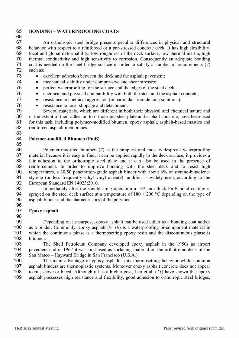
BONDING – WATERPROOFING COATS 65 66 An orthotropic steel bridge presents peculiar differences in physical and structural 67 behavior with respect to a reinforced or a pre-stressed concrete deck. It has high flexibility, 68 local and global deformability, low roughness of the deck surface, low thermal inertia, high 69 thermal conductivity and high sensitivity to corrosion. Consequently an adequate bonding 70 coat is needed on the steel bridge surface in order to satisfy a number of requirements (7) 71 such as: 72
excellent adhesion between the deck and the asphalt pavement; 73
mechanical stability under compressive and shear stresses; 74
perfect waterproofing for the surface and the edges of the steel deck; 75
chemical and physical compatibility with both the steel and the asphalt concrete; 76
resistance to chemical aggression (in particular from deicing solutions); 77
resistance to local slippage and detachment. 78 Several materials, which are different in both their physical and chemical nature and 79 in the extent of their adhesion to orthotropic steel plate and asphalt concrete, have been used 80 for this task, including polymer-modified bitumen, epoxy asphalt, asphalt-based mastics and 81 reinforced asphalt membranes. 82 83 Polymer-modified Bitumen (PmB) 84 85 Polymer-modified bitumen (7) is the simplest and most widespread waterproofing 86 material because it is easy to find, it can be applied rapidly to the deck surface, it provides a 87 fair adhesion to the orthotropic steel plate and it can also be used in the presence of 88 reinforcement. In order to improve bonding with the steel deck and to resist high 89 temperatures, a 30/50 penetration-grade asphalt binder with about 6% of styrene-butadiene-90 styrene (or less frequently ethyl vinyl acetate) modifier is widely used, according to the 91 European Standard EN 14023:2010. 92 Immediately after the sandblasting operation a 1÷2 mm-thick PmB bond coating is 93 sprayed on the steel deck surface at a temperature of 180 ÷ 200 °C depending on the type of 94 asphalt binder and the characteristics of the polymer. 95 96 Epoxy asphalt 97 98 Depending on its purpose, epoxy asphalt can be used either as a bonding coat and/or 99 as a binder. Commonly, epoxy asphalt (9, 10) is a waterproofing bi-component material in 100 which the continuous phase is a thermosetting epoxy resin and the discontinuous phase is 101 bitumen. 102 The Shell Petroleum Company developed epoxy asphalt in the 1950s as airport 103 pavement and in 1967 it was first used as surfacing material on the orthotropic deck of the 104 San Mateo – Hayward Bridge in San Francisco (U.S.A.). 105 The main advantage of epoxy asphalt is its thermosetting behavior while common 106 asphalt binders are thermoplastic systems. Moreover epoxy asphalt concrete does not appear 107 to rut, shove or bleed. Although it has a higher cost, Luo et al. (11) have shown that epoxy 108 asphalt possesses high resistance and flexibility, good adhesion to orthotropic steel bridges, 109
TRB 2012 Annual Meeting Paper revised from original submittal.
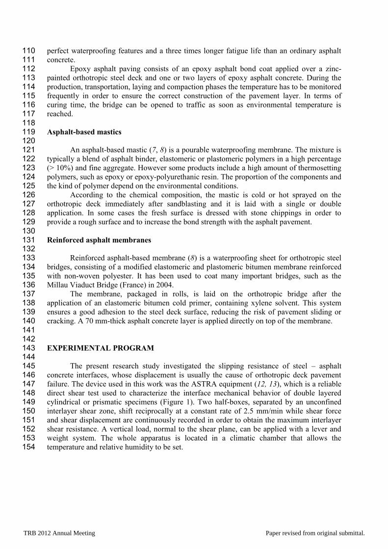
perfect waterproofing features and a three times longer fatigue life than an ordinary asphalt 110 concrete. 111 Epoxy asphalt paving consists of an epoxy asphalt bond coat applied over a zinc-112 painted orthotropic steel deck and one or two layers of epoxy asphalt concrete. During the 113 production, transportation, laying and compaction phases the temperature has to be monitored 114 frequently in order to ensure the correct construction of the pavement layer. In terms of 115 curing time, the bridge can be opened to traffic as soon as environmental temperature is 116 reached. 117 118 Asphalt-based mastics 119 120 An asphalt-based mastic (7, 8) is a pourable waterproofing membrane. The mixture is 121 typically a blend of asphalt binder, elastomeric or plastomeric polymers in a high percentage 122 (> 10%) and fine aggregate. However some products include a high amount of thermosetting 123 polymers, such as epoxy or epoxy-polyurethanic resin. The proportion of the components and 124 the kind of polymer depend on the environmental conditions. 125 According to the chemical composition, the mastic is cold or hot sprayed on the 126 orthotropic deck immediately after sandblasting and it is laid with a single or double 127 application. In some cases the fresh surface is dressed with stone chippings in order to 128 provide a rough surface and to increase the bond strength with the asphalt pavement. 129 130 Reinforced asphalt membranes 131 132 Reinforced asphalt-based membrane (8) is a waterproofing sheet for orthotropic steel 133 bridges, consisting of a modified elastomeric and plastomeric bitumen membrane reinforced 134 with non-woven polyester. It has been used to coat many important bridges, such as the 135 Millau Viaduct Bridge (France) in 2004. 136 The membrane, packaged in rolls, is laid on the orthotropic bridge after the 137 application of an elastomeric bitumen cold primer, containing xylene solvent. This system 138 ensures a good adhesion to the steel deck surface, reducing the risk of pavement sliding or 139 cracking. A 70 mm-thick asphalt concrete layer is applied directly on top of the membrane. 140 141 142 EXPERIMENTAL PROGRAM 143 144 The present research study investigated the slipping resistance of steel – asphalt 145 concrete interfaces, whose displacement is usually the cause of orthotropic deck pavement 146 failure. The device used in this work was the ASTRA equipment (12, 13), which is a reliable 147 direct shear test used to characterize the interface mechanical behavior of double layered 148 cylindrical or prismatic specimens (Figure 1). Two half-boxes, separated by an unconfined 149 interlayer shear zone, shift reciprocally at a constant rate of 2.5 mm/min while shear force 150 and shear displacement are continuously recorded in order to obtain the maximum interlayer 151 shear resistance. A vertical load, normal to the shear plane, can be applied with a lever and 152 weight system. The whole apparatus is located in a climatic chamber that allows the 153 temperature and relative humidity to be set. 154
TRB 2012 Annual Meeting Paper revised from original submittal.
To simulate the orthotropic steel deck pavement system, double-layered specimens 155 were manufactured: the first layer was a 30 mm-thick steel plate while the second layer was a 156 40 mm-thick hot mix asphalt (HMA) course. Between the two materials a PmB bonding coat 157 was applied in order to provide both adhesion and waterproofing. 158 The experimental program was planned so as to investigate the physical behavior of 3 159 steel surfaces (smooth, net-reinforced and bar-reinforced) at the interface with the upper 160 asphalt concrete layer. Test parameters were chosen as follows: temperature equal to 20°C 161 and 40°C and normal load of 0 MPa, 0.2 MPa and 0.4 MPa. Four repetitions were performed 162 for each test condition. 163 The aim of this study was to compare the shear properties of each steel-asphalt 164 concrete interface in order to assess the benefit of the reinforcement in different thermal and 165 normal load conditions. 166 167
168 169
FIGURE 1 ASTRA Device 170 171 172 SPECIMEN PREPARATION PROCEDURE 173 174 The dimensions of the lower steel layer of the specimen are 97.5 × 97.5 × 30 mm 175
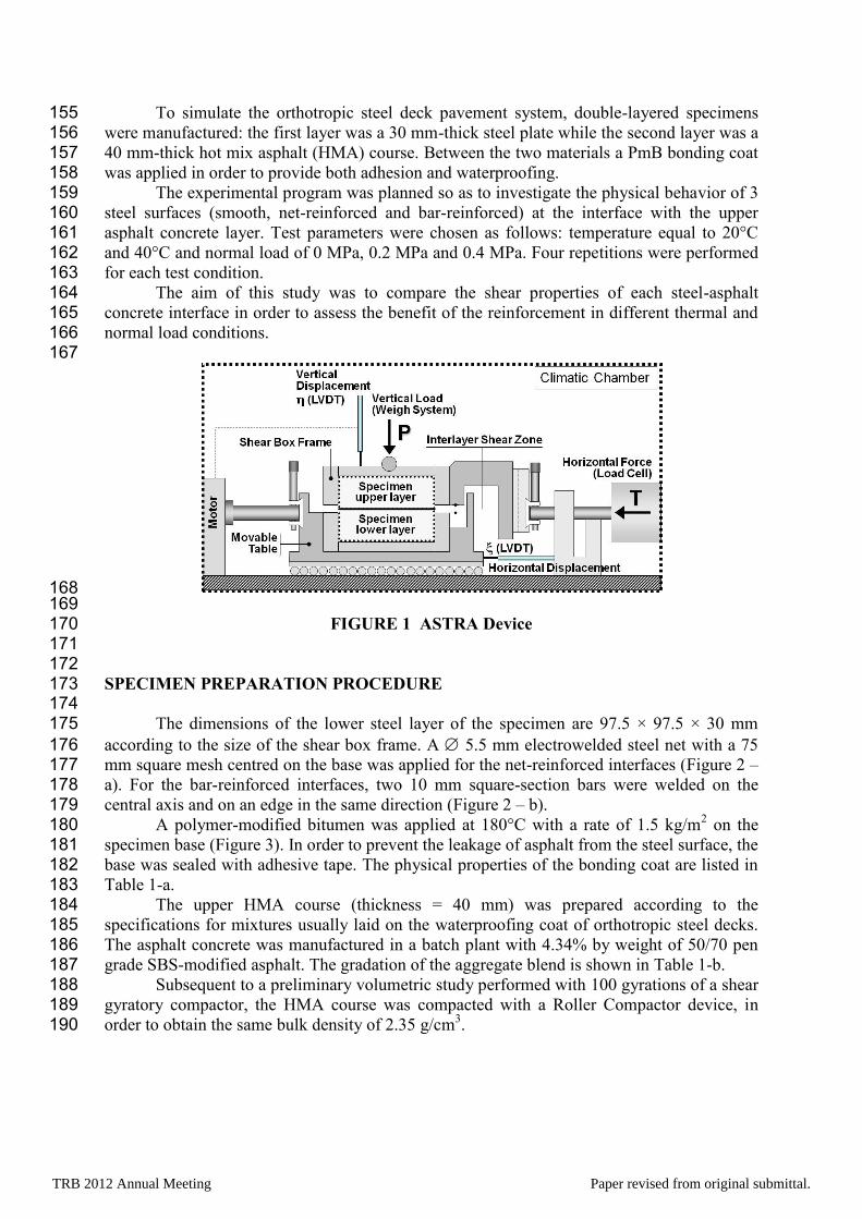
according to the size of the shear box frame. A 5.5 mm electrowelded steel net with a 75 176 mm square mesh centred on the base was applied for the net-reinforced interfaces (Figure 2 – 177 a). For the bar-reinforced interfaces, two 10 mm square-section bars were welded on the 178 central axis and on an edge in the same direction (Figure 2 – b). 179 A polymer-modified bitumen was applied at 180°C with a rate of 1.5 kg/m
2 on the 180
specimen base (Figure 3). In order to prevent the leakage of asphalt from the steel surface, the 181 base was sealed with adhesive tape. The physical properties of the bonding coat are listed in 182 Table 1-a. 183 The upper HMA course (thickness = 40 mm) was prepared according to the 184 specifications for mixtures usually laid on the waterproofing coat of orthotropic steel decks. 185 The asphalt concrete was manufactured in a batch plant with 4.34% by weight of 50/70 pen 186 grade SBS-modified asphalt. The gradation of the aggregate blend is shown in Table 1-b. 187 Subsequent to a preliminary volumetric study performed with 100 gyrations of a shear 188 gyratory compactor, the HMA course was compacted with a Roller Compactor device, in 189 order to obtain the same bulk density of 2.35 g/cm
3. 190
TRB 2012 Annual Meeting Paper revised from original submittal.
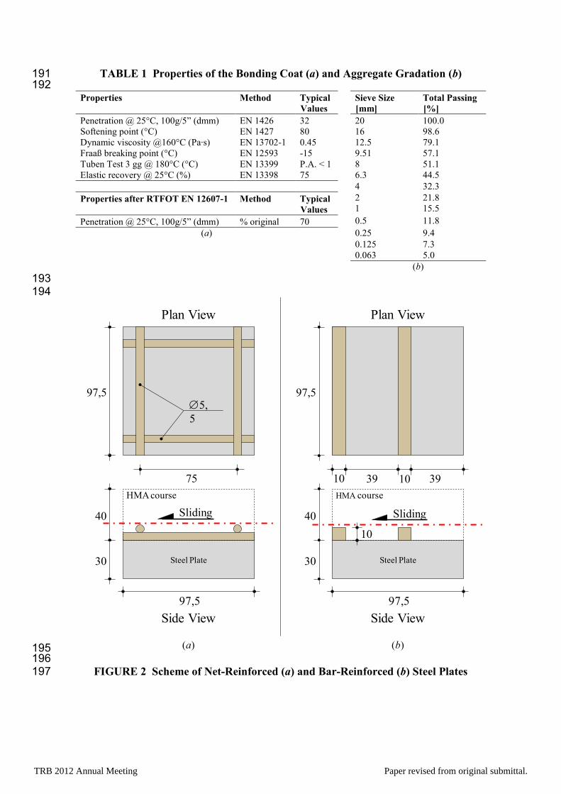
TABLE 1 Properties of the Bonding Coat (a) and Aggregate Gradation (b) 191 192
Properties Method Typical
Values
Sieve Size
[mm]
Total Passing
[%]
Penetration @ 25°C, 100g/5” (dmm) EN 1426 32 20 100.0
Softening point (°C) EN 1427 80 16 98.6
Dynamic viscosity @160°C (Pa∙s) EN 13702-1 0.45 12.5 79.1
Fraaß breaking point (°C) EN 12593 -15 9.51 57.1
Tuben Test 3 gg @ 180°C (°C) EN 13399 P.A. < 1 8 51.1
Elastic recovery @ 25°C (%) EN 13398 75 6.3 44.5
4 32.3
Properties after RTFOT EN 12607-1 Method Typical
Values
2
1
21.8
15.5
Penetration @ 25°C, 100g/5” (dmm) % original 70 0.5 11.8
(a) 0.25 9.4
0.125 7.3
0.063 5.0
(b)
193 194
195 196
FIGURE 2 Scheme of Net-Reinforced (a) and Bar-Reinforced (b) Steel Plates 197
Steel Plate30
97,5
10
Side View
(b)
Plan View
40
HMA course
Sliding
97,5
10 3939
10
Steel Plate30
97,5
75
5,
5
Side View
(a)
Plan View
40
HMA course
Sliding
97,5
TRB 2012 Annual Meeting Paper revised from original submittal.
198 199
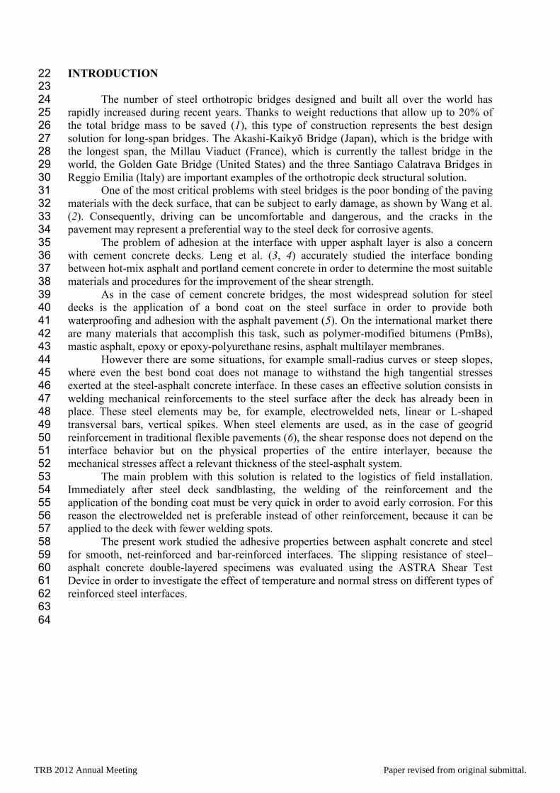
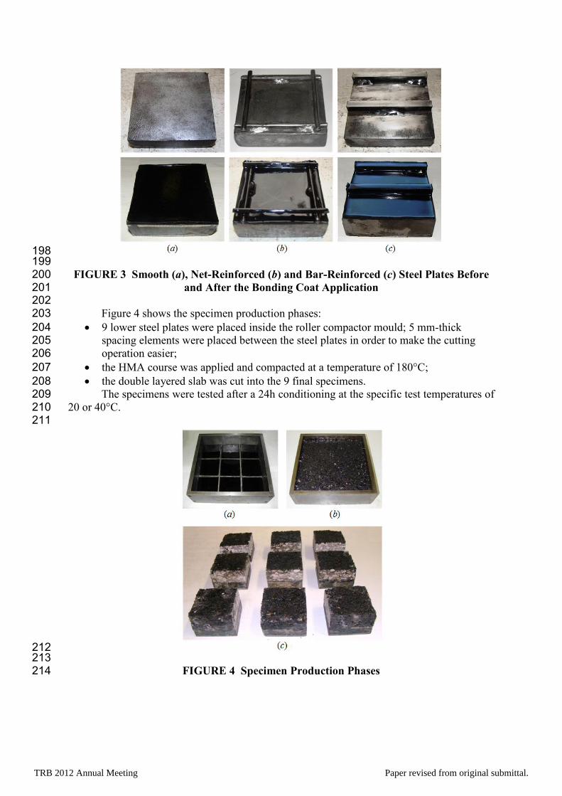
FIGURE 3 Smooth (a), Net-Reinforced (b) and Bar-Reinforced (c) Steel Plates Before 200 and After the Bonding Coat Application 201
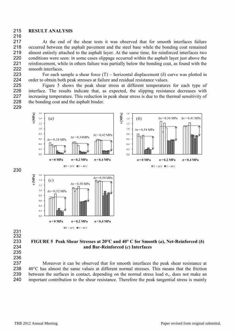
202 Figure 4 shows the specimen production phases: 203
9 lower steel plates were placed inside the roller compactor mould; 5 mm-thick 204 spacing elements were placed between the steel plates in order to make the cutting 205 operation easier; 206
the HMA course was applied and compacted at a temperature of 180°C; 207
the double layered slab was cut into the 9 final specimens. 208 The specimens were tested after a 24h conditioning at the specific test temperatures of 209 20 or 40°C. 210 211
212 213
FIGURE 4 Specimen Production Phases 214
TRB 2012 Annual Meeting Paper revised from original submittal.
RESULT ANALYSIS 215 216 At the end of the shear tests it was observed that for smooth interfaces failure 217 occurred between the asphalt pavement and the steel base while the bonding coat remained 218 almost entirely attached to the asphalt layer. At the same time, for reinforced interfaces two 219 conditions were seen: in some cases slippage occurred within the asphalt layer just above the 220 reinforcement, while in others failure was partially below the bonding coat, as found with the 221 smooth interfaces. 222 For each sample a shear force (T) – horizontal displacement (δ) curve was plotted in 223 order to obtain both peak stresses at failure and residual resistance values. 224 Figure 5 shows the peak shear stress at different temperatures for each type of 225 interface. The results indicate that, as expected, the slipping resistance decreases with 226 increasing temperature. This reduction in peak shear stress is due to the thermal sensitivity of 227 the bonding coat and the asphalt binder. 228 229
230
231 232
FIGURE 5 Peak Shear Stresses at 20°C and 40° C for Smooth (a), Net-Reinforced (b) 233 and Bar-Reinforced (c) Interfaces 234
235 236 Moreover it can be observed that for smooth interfaces the peak shear resistance at 237 40°C has almost the same values at different normal stresses. This means that the friction 238 between the surfaces in contact, depending on the normal stress load σv, does not make an 239 important contribution to the shear resistance. Therefore the peak tangential stress is mainly 240
0,0
0,2
0,4
0,6
0,8
1,0
1,2
1,4
1,6
σ = 0 MPa σ = 0,2 MPa σ = 0,4 MPa
τ[M
Pa
]
(a)
T = 20°C T = 40°C
Δτ = 0,28 MPa Δτ = 0,34MPa
Δτ = 0,42 MPa
0,0
0,2
0,4
0,6
0,8
1,0
1,2
1,4
1,6
σ = 0 MPa σ = 0,2 MPa σ = 0,4 MPa
τ[M
Pa
](b)
T = 20°C T = 40°C
Δτ = 0,54 MPa
Δτ = 0,56 MPa Δτ = 0,41 MPa
0,0
0,2
0,4
0,6
0,8
1,0
1,2
1,4
1,6
σ = 0 MPa σ = 0,2 MPa σ = 0,4 MPa
τ[M
Pa
]
(c)
T = 20°C T = 40°C
Δτ = 0,52 MPa
Δτ = 0,50 MPa
Δτ = 0,50 MPa
TRB 2012 Annual Meeting Paper revised from original submittal.
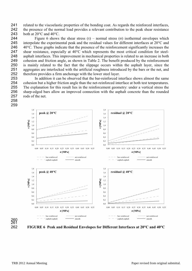
related to the viscoelastic properties of the bonding coat. As regards the reinforced interfaces, 241 the presence of the normal load provides a relevant contribution to the peak shear resistance 242 both at 20°C and 40°C. 243 Figure 6 shows the shear stress (τ) – normal stress (σ) isothermal envelopes which 244 interpolate the experimental peak and the residual values for different interfaces at 20°C and 245 40°C. These graphs indicate that the presence of the reinforcement significantly increases the 246 shear resistance, especially at 40°C which represents the most critical condition for steel-247 asphalt interfaces. This improvement in mechanical properties is related to an increase in both 248 cohesion and friction angle, as shown in Table 2. The benefit produced by the reinforcement 249 is mainly related to the fact that the slippage occurs within the asphalt layer, since the 250 aggregates are interlocked with the artificial roughness introduced by the bars or the net, and 251 therefore provides a firm anchorage with the lower steel layer. 252 In addition it can be observed that the bar-reinforced interface shows almost the same 253 cohesion but a higher friction angle than the net-reinforced interface at both test temperatures. 254 The explanation for this result lies in the reinforcement geometry: under a vertical stress the 255 sharp-edged bars allow an improved connection with the asphalt concrete than the rounded 256 rods of the net. 257 258 259
260 261
FIGURE 6 Peak and Residual Envelopes for Different Interfaces at 20°C and 40°C 262
0,0
0,2
0,4
0,6
0,8
1,0
1,2
1,4
1,6
1,8
0,00 0,05 0,10 0,15 0,20 0,25 0,30 0,35 0,40 0,45 0,50 0,55
τ[M
Pa
]
σ [MPa]
peak @ 20 C
bar-reinforced net-reinforced
asphalt-asphalt smooth
0,0
0,2
0,4
0,6
0,8
1,0
1,2
1,4
1,6
1,8
0,00 0,05 0,10 0,15 0,20 0,25 0,30 0,35 0,40 0,45 0,50 0,55
τ[M
Pa
]
σ [MPa]
residual @ 20 C
bar-reinforced net-reinforced
asphalt-asphalt smooth
0,0
0,2
0,4
0,6
0,8
1,0
1,2
1,4
1,6
1,8
0,00 0,05 0,10 0,15 0,20 0,25 0,30 0,35 0,40 0,45 0,50 0,55
τ[M
Pa
]
σ [MPa]
peak @ 40 C
bar-reinforced net-reinforced
asphalt-asphalt smooth
0,0
0,2
0,4
0,6
0,8
1,0
1,2
1,4
1,6
1,8
0,00 0,05 0,10 0,15 0,20 0,25 0,30 0,35 0,40 0,45 0,50 0,55
τ[M
Pa
]
σ [MPa]
residual @ 40 C
bar-reinforced net-reinforced
asphalt-asphalt smooth
TRB 2012 Annual Meeting Paper revised from original submittal.
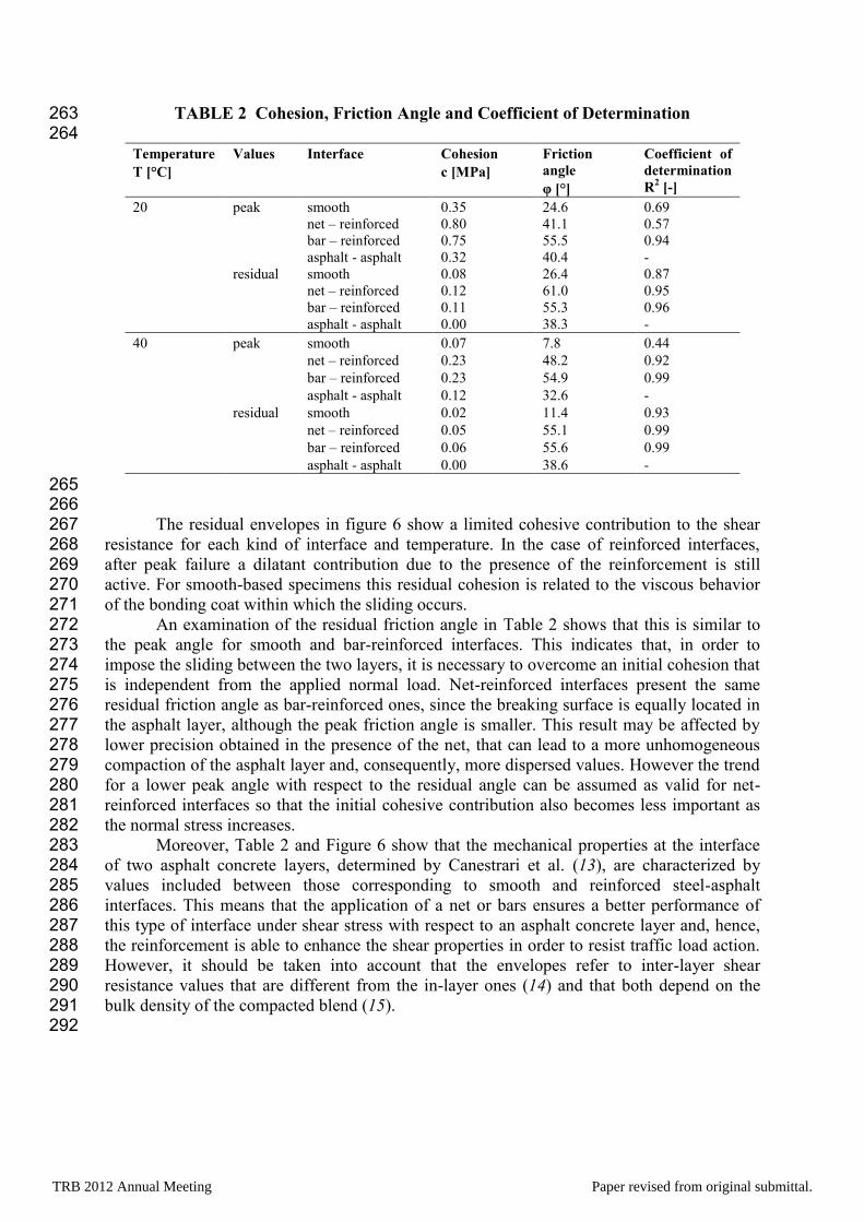
TABLE 2 Cohesion, Friction Angle and Coefficient of Determination 263 264
Temperature
T [°C]
Values Interface Cohesion
c [MPa]
Friction
angle
υ [ ]
Coefficient of
determination
R2 [-]
20 peak smooth 0.35 24.6 0.69
net – reinforced 0.80 41.1 0.57
bar – reinforced 0.75 55.5 0.94
asphalt - asphalt 0.32 40.4 -
residual smooth 0.08 26.4 0.87
net – reinforced 0.12 61.0 0.95
bar – reinforced 0.11 55.3 0.96
asphalt - asphalt 0.00 38.3 -
40 peak smooth 0.07 7.8 0.44
net – reinforced 0.23 48.2 0.92
bar – reinforced 0.23 54.9 0.99
asphalt - asphalt 0.12 32.6 -
residual smooth 0.02 11.4 0.93
net – reinforced 0.05 55.1 0.99
bar – reinforced 0.06 55.6 0.99
asphalt - asphalt 0.00 38.6 -
265 266 The residual envelopes in figure 6 show a limited cohesive contribution to the shear 267 resistance for each kind of interface and temperature. In the case of reinforced interfaces, 268 after peak failure a dilatant contribution due to the presence of the reinforcement is still 269 active. For smooth-based specimens this residual cohesion is related to the viscous behavior 270 of the bonding coat within which the sliding occurs. 271 An examination of the residual friction angle in Table 2 shows that this is similar to 272 the peak angle for smooth and bar-reinforced interfaces. This indicates that, in order to 273 impose the sliding between the two layers, it is necessary to overcome an initial cohesion that 274 is independent from the applied normal load. Net-reinforced interfaces present the same 275 residual friction angle as bar-reinforced ones, since the breaking surface is equally located in 276 the asphalt layer, although the peak friction angle is smaller. This result may be affected by 277 lower precision obtained in the presence of the net, that can lead to a more unhomogeneous 278 compaction of the asphalt layer and, consequently, more dispersed values. However the trend 279 for a lower peak angle with respect to the residual angle can be assumed as valid for net-280 reinforced interfaces so that the initial cohesive contribution also becomes less important as 281 the normal stress increases. 282 Moreover, Table 2 and Figure 6 show that the mechanical properties at the interface 283 of two asphalt concrete layers, determined by Canestrari et al. (13), are characterized by 284 values included between those corresponding to smooth and reinforced steel-asphalt 285 interfaces. This means that the application of a net or bars ensures a better performance of 286 this type of interface under shear stress with respect to an asphalt concrete layer and, hence, 287 the reinforcement is able to enhance the shear properties in order to resist traffic load action. 288 However, it should be taken into account that the envelopes refer to inter-layer shear 289 resistance values that are different from the in-layer ones (14) and that both depend on the 290 bulk density of the compacted blend (15). 291 292
TRB 2012 Annual Meeting Paper revised from original submittal.
CONCLUSIONS 293 294 Despite the fact that many steel orthotropic decks show a lack of adhesion with the 295 upper asphalt course, especially in the presence of high tangential stresses (small-radius 296 curves, steep slopes), there is still a considerable lack of experimental data on this topic. The 297 problem of structural compatibility at the interface between the steel deck and the asphalt 298 concrete was studied in this experimental research in order to determine the shear properties 299 of smooth and reinforced steel surfaces coated with a hard-modified bitumen. Two 300 temperatures and three different normal loads were investigated. A specimen preparation 301 procedure was also defined. 302 The main result of this work demonstrates that the shear resistance of the reinforced 303 interfaces was at least twice that of the smooth interface in each test configuration. The 304 primary reason for this is the localization of the slippage, which for the smooth interface 305 occurs inside the bonding coat while for the reinforced interfaces it is entirely or partially 306 within the asphalt layer. 307 The benefit due to the reinforcement can be observed in terms of both cohesion and 308 friction angle. Moreover, this contribution increases with the temperature, permitting the 309 achievement of shear strength values at the interface higher than those found with a typical 310 double-layered asphalt interface. 311 Future experimental research on this topic will involve the different types of bonding 312 coats described in this paper. 313
314
TRB 2012 Annual Meeting Paper revised from original submittal.
REFERENCES 315
316
1. Mangus, A. Orthotropic Steel Deck Bridges Landmarks of Our Infrastructure in 317 California 1965-2009. Western Bridge Engineers’ Seminar, Sacramento, 2009. 318
2. Wang, X., X. Chen, G. Cheng, and W. Huang. Cracking of the Asphalt Surfacing of the 319 Longest Suspension Steel Bridge in China. 24th Southern African Transport 320 Conference, Pretoria, 2005. 321
3. Leng, Z., H. Ozer, I. L. Al-Qadi, and S. H. Carpenter. Interface Bonding Between Hot-322 Mix Asphalt and Various Portland Cement Concrete Surfaces: Laboratory Assessment. 323 In Transportation Research Record: Journal of the Transportation Research Board, 324 No. 2057, Transportation Research Board of the National Academies, Washington, D. 325 C., 2008, pp.46-53. 326
4. Leng, Z., I. L. Al-Qadi, S. H. Carpenter, and H. Ozer. Interface Bonding Between Hot-327 Mix Asphalt and Various Portland Cement Concrete Surfaces: Assessment of 328 Accelerated Pavement Testing and Measurement of Interface Strain. In Transportation 329 Research Record: Journal of the Transportation Research Board, No. 2127, 330 Transportation Research Board of the National Academies, Washington, D. C., 2009, 331 pp.20-28. 332
5. Medani, T. O. Asphalt Surfacing Applied to Orthotropic Steel Bridge Decks. Report 7-333 01-127-1. Delft University of Technology, 2001. 334
6. Ferrotti, G., F. Canestrari, A. Virgili, and A. Grilli. A Strategic Laboratory Approach 335 for the Performance Investigation of Geogrids in Flexible Pavements. Construction and 336 Building Materials, Vol. 25, Issue 5, 2011, pp. 2343-2348. 337
7. Hicks G., I. Dussek, and C. Seim. Asphalt Surfaces on Steel Bridge Decks. In 338 Transportation Research Record: Journal of the Transportation Research Board, No. 339 1740, Transportation Research Board of the National Academies, Washington, D. C., 340 2000, pp.135-142. 341
8. Edwards, Y., and P. Westergren. Polymer Modified Waterproofing and Pavement 342 System for the High Coast Bridge in Sweden. VTI Rapport 430A, 2001. 343
9. Huang, W., Z. Qian, G. Chen, and J. Yang. Epoxy Asphalt Concrete Paving on the 344 Deck of Long-Span Steel Bridges. Chinese Science Bulletin, Vol. 48, No. 21, 2001, pp. 345 2391-2394. 346
10. Yu J., P. Cong, and S. Wu. Laboratory Investigation of the Properties of Asphalt 347 Modified with Epoxy Resin. Journal of Applied Polymer Science, Vol. 113, Issue 6, 348 2009, pp. 3557-3563. 349
11. Luo, S., J. Wang, and Z. Qian. Research on the Performance of Locally Developed 350 Epoxy Asphalt Mixes. 26th Southern African Transport Conference, Pretoria, 2007. 351
12. Santagata, F. A., G. Ferrotti, M. N. Partl, and F. Canestrari. Statistical Investigation of 352 Two Different Interlayer Shear Test Methods. Materials and Structures, No.42, 2009, 353 pp. 705-714. 354
13. Canestrari, F., G. Ferrotti, M. N. Partl, and E. Santagata. Advanced Testing and 355 Characterization of Interlayer Shear Resistance. In Transportation Research Record: 356 Journal of the Transportation Research Board, No. 1929, Transportation Research 357 Board of the National Academies, Washington, D. C., 2005, pp.69-78. 358
TRB 2012 Annual Meeting Paper revised from original submittal.
14. Partl, M. N., and C. Raab. Shear Adhesion between Top Layers of Fresh Asphalt 359 Pavements in Switzerland. 7th Conference on Asphalt Pavements for Southern Africa, 360 Victory Falls, 1999. 361
15. Santagata, F. A., M. N. Partl, G. Ferrotti, F. Canestrari, and A. Flisch. Layer 362 Characteristics Affecting Interlayer Shear Resistance in Flexible Pavements. 83rd 363 Annual Meeting AAPT, Philadelphia, 2008. 364
TRB 2012 Annual Meeting Paper revised from original submittal.